EP0240159A1 - Maschine zum Einpressen von Sicherheitsmuttern - Google Patents
Maschine zum Einpressen von Sicherheitsmuttern Download PDFInfo
- Publication number
- EP0240159A1 EP0240159A1 EP19870301765 EP87301765A EP0240159A1 EP 0240159 A1 EP0240159 A1 EP 0240159A1 EP 19870301765 EP19870301765 EP 19870301765 EP 87301765 A EP87301765 A EP 87301765A EP 0240159 A1 EP0240159 A1 EP 0240159A1
- Authority
- EP
- European Patent Office
- Prior art keywords
- nut
- location
- piston
- air
- line
- Prior art date
- Legal status (The legal status is an assumption and is not a legal conclusion. Google has not performed a legal analysis and makes no representation as to the accuracy of the status listed.)
- Withdrawn
Links
- 238000003780 insertion Methods 0.000 claims abstract description 19
- 230000037431 insertion Effects 0.000 claims abstract description 19
- 230000003584 silencer Effects 0.000 description 3
- 230000000284 resting effect Effects 0.000 description 2
- 239000002023 wood Substances 0.000 description 2
- 238000010276 construction Methods 0.000 description 1
- 230000000881 depressing effect Effects 0.000 description 1
- 238000010586 diagram Methods 0.000 description 1
- 238000002347 injection Methods 0.000 description 1
- 239000007924 injection Substances 0.000 description 1
- 239000000463 material Substances 0.000 description 1
- 230000000717 retained effect Effects 0.000 description 1
Images


Classifications
-
- B—PERFORMING OPERATIONS; TRANSPORTING
- B23—MACHINE TOOLS; METAL-WORKING NOT OTHERWISE PROVIDED FOR
- B23P—METAL-WORKING NOT OTHERWISE PROVIDED FOR; COMBINED OPERATIONS; UNIVERSAL MACHINE TOOLS
- B23P19/00—Machines for simply fitting together or separating metal parts or objects, or metal and non-metal parts, whether or not involving some deformation; Tools or devices therefor so far as not provided for in other classes
- B23P19/04—Machines for simply fitting together or separating metal parts or objects, or metal and non-metal parts, whether or not involving some deformation; Tools or devices therefor so far as not provided for in other classes for assembling or disassembling parts
- B23P19/06—Screw or nut setting or loosening machines
- B23P19/062—Pierce nut setting machines
Definitions
- the present invention relates to a machine for inserting and securing nuts of the type comprising a body portion adapted to be received in an aperture in a workpiece and with a threaded bore therein and a toothed anchorage flange therearound.
- T-Nuts nuts of this type, known as "T-Nuts" are employed to secure various parts of the pieces of furniture together.
- T-Nuts consists of a generally cylindrical base defining a passage which is threaded, from which there extends an annular flange having projections (spikes) which are engaged within a piece of timber when the base is located within a hole preformed in the piece of timber.
- these T-Nuts have been inserted by hand using a hammer.
- T-Nuts The manual insertion of T-Nuts is time-consuming and labour intensive, and is therefore costly.
- the machine is characterised in that it comprises a body, nut supply means mounted on the body and adapted to locate the nut, at least one at a time, at a holding location, and an insertion assembly including transfer means to transfer the nut from the holding location to an insertion location and motor means engageable on the nut at the insertion location to apply a force to insert the nut in the aperture and secure the flange to the workpiece.
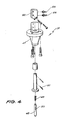
- FIG. 6 there is illustrated a T-Nut 77 having a cylindrical body portion or base and an annular flange 78.
- the base 79 provides a threaded passage 80. Punched from the flange 78 are spikes 81, so that holes 82 are formed. In use the base 79 is received in a circular hole formed in a piece of timber. The spikes 81 are driven into the timber to secure the T-Nut 77 in position.
- a T-Net insertion machine 10 having a body 11 housing an insertion assembly 12.
- the assembly 12 receives T-Nuts from a vibratory feeder 13 which delivers T-Nuts in a particular orientation to the opening 14.
- a locating pin assembly switch 15 vertically aligned with the insertion assembly 12.
- the locating assembly 12 and safety switch 15 are mounted on an arm 16 below which there is defined a recess 17 into which a timber product is introduced.
- the timber product has a aperture which receives the body portion 79 of the T-Nut to be inserted by the insertion assembly 12.
- Controlling the operation of the assembly 12 is an operator station 18 having a pedal 19 manipulated by the operator.
- the assembly 12 includes a pneumatic ram 20 having a cylinder 21 closed at each end by plates 22 and 23. Located within the cylinder 21 is a piston assembly 24 including seals 25 and piston 26. Extending upwardly from the piston 26 and attached thereto is a piston rod 27 terminating at is upper end with a locator member 28. The piston assembly 24 sealingly divides the pneumatic chamber within the cylinder 21 into upper and lower sub-chambers. The end pIate 23 is provided with a central passage 29 through which the piston rod 27 sealingly passes via a bush 30. The two end plates 22 and 23 are held in position by means of threaded rods 31 and nuts 32. Air is delivered to the interior of the cylinder 21 by means of passages 33 and 34.
- a T-Nut delivery member 35 having a passage 30 through which the rod 27 and member 28 pass to engage a T-Nut to force the T-Nut into the piece of timber positioned thereabove.
- the member 35 is secured to the plate 23 by means of bolts 37.
- Extending in from one edge of the member is a holding slot 38 which delivers the T-Nut to a position partly projecting into the passage 36 and resting on top of the locating member 28.
- the slot 38 has an upwardly extending step 39 against which the T-Nut abuts prior to delivery to a position above the passage 36.
- Formed in the member 36 is a passage which receives a piston 40. The piston 40 is air driven and raises the T-Nut over the step 39.
- a stop member 41 which in co-operation with the slot 38 defines a space within which a T-Nut is located prior to being delivered to the passage 36.
- a wire 42 which projects into the opening 14 to guide the T-Nuts from within the vibratory feeder 13 to the slot 38.
- the wire 42 has one end received within a passage 43 and is clamped in position by means of a screw 44.
- a nozzle 45 which directs air to engage the T-Nut abutting the step 39.
- the nozzle 45 is mounted on a rigid tube 46 fixed to the member 4l.
- the assembly 15 includes a main body 47 within which there is mounted a movable piston 48 biassed to an extended position by means of a spring 49.
- the piston 48 is retained in position by means of a slot 50 engaged by a pin 51.
- the piston 48 operates a swtich 52 to selectively connect pneumatic lines 53 and 54. More particularly, upon the piston 48 being moved to a retracted position, the lines 53 and 54 are connected to allow the flow of compressed air therebetween.
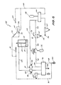
- the pneumatic circuit 55 includes main pressure supply lines 56 and reservoirs 75 and 58.
- the reservoir 75 stores sufficient compressed air to actuate, once only per charge, to operate a main spool valve 74. Thereafter mains pressure air is delivered to the line 59 via a port sensor 60 to one end of the cylinder 21 to cause the piston rod 27 to rise and insert a T-Nut located in the passage 36.
- the spool valve has been actuated by the delivery of the charge of air from the reservoir 75 to the line 61, by the depression of the pedal 19, the spool valve 74 remains in the activated position.
- the port sensor 60 While air is passing through the line 59, the port sensor 60 isolates the line 62 from the main air supply 56. Once the piston 24 has reached its uppermost limit, the port sensor 60 allows the delivery of main pressure air to the line 62. Air is exhausted from above the piston 24 via line 63. This exhaust air is delivered via valve 74 to a silencer 64. Located in the line 63 is a port sensor 65 which delivers main pressure air to a timer valve 57 when air ceases to flow through the line 63. The timer valve 57 after a predetermined period of time delivers air to the valve 74 to move the valve 74 to the start position. Again it should be appreciated that the port sensor 65 only delivers air to the timer valve 57 when air ceases to flow through the line 63.
- the reservoir 75 is charged upon air being delivered to the line 62 and then subsequently to the line 54.
- Air delivered to the line 62 also operates the injection valve 66 so that air is selcetively delivered to the reservoir 67. Additionally, the valve 66 selectively delivers a charge of air from the reservoir 58 to the line 68.
- Communicating with the line 68 is the piston 40 which raises the T-Nut over the step 39. Also communicating with the line 68 is the injector nozzle 45 which moves the raised T-Nut to a position partly projecting into the passage 36 and resting on the member 28.
- Extending from the valve 74 to the silencer 64 is a line 69.
- Extending from the line 69 is a further line 70 which delivers exhaust air to a first reject nozzle 71 and a second reject nozzle 72.
- the reject nozzle 72 is formed in the delivery member 35.
- This exhaust air passing through the line 70 is also delivered to a feeder nozzle 73.
- the feeder nozzle aids in moving the T-Nut from the opening 14 to a position abutting the step 39.
- the ejector nozzle 71 removes a T-Nut still located on the member 28 after a completed stroke of the piston rod 27, if such a problem has occurred.
- the ejector nozzle 72 removes a T-Nut from the position adjacent the step 39, if the T-Nut has not been moved by the nozzle 45 to a position on top of the member 28.
- air is delivered to the reservoir 75 upon the piston 48 being engaged by a piece of wood moved by the operator.
- air is delivered from the line 54 to 53.
- Air from the line 53 is automatically fed to the reservoir 75.
- air from the reservoir is delivered as control air to operate the valve 74.
- the valve 74 is moved to the operative position wherein main pressure air is delivered from the line 56 to the lower surface of the piston 24, via the port sensor 60.
- valve 66 when main pressure is delivered to the line 62, the valve 66 is operated so that air in the reservoir 58 is delivered to the line 68. In the rest position, the valve 66 delivers air from the regulator 67 to the reservoir 58.
- the piston 48 and switch 52 act as a safety switch in that if the piston 48 is not retracted by the operator inserting a piece of wood in the appropriate position, the switch 52 dumps air from the reservoir 75 via line 76 to atmosphere.
- locating members 28 can be provided, and being of different sizes. This then allows the operator to select the locating member 28 to suit the particular sized T-Nut being used.
- timer valve 57 can be altered to suit different materials into which the T-Nuts are being inserted.
Landscapes
- Engineering & Computer Science (AREA)
- Mechanical Engineering (AREA)
- Automatic Assembly (AREA)
Applications Claiming Priority (3)
| Application Number | Priority Date | Filing Date | Title |
|---|---|---|---|
| AUPH482686 | 1986-02-28 | ||
| AU4826/86 | 1986-02-28 | ||
| AU69296/87A AU583977B2 (en) | 1986-02-28 | 1987-02-26 | A ``T-nut" insertion machine |
Publications (1)
| Publication Number | Publication Date |
|---|---|
| EP0240159A1 true EP0240159A1 (de) | 1987-10-07 |
Family
ID=25635954
Family Applications (1)
| Application Number | Title | Priority Date | Filing Date |
|---|---|---|---|
| EP19870301765 Withdrawn EP0240159A1 (de) | 1986-02-28 | 1987-02-27 | Maschine zum Einpressen von Sicherheitsmuttern |
Country Status (1)
| Country | Link |
|---|---|
| EP (1) | EP0240159A1 (de) |
Citations (6)
| Publication number | Priority date | Publication date | Assignee | Title |
|---|---|---|---|---|
| US2398659A (en) * | 1943-12-06 | 1946-04-16 | Theodore E Mead | Work feeding device |
| US3528157A (en) * | 1966-08-24 | 1970-09-15 | Litton Precision Prod Inc | Press tools |
| US4164072A (en) * | 1976-12-11 | 1979-08-14 | Yugenkaisha Shinjo Seisakusho | Automatic piercing nut assembling arrangement |
| DE3446978A1 (de) * | 1983-12-21 | 1985-08-14 | Profil-Verbindungstechnik Gmbh & Co Kg, 6382 Friedrichsdorf | Verfahren und vorrichtung zum befestigen eines hohlkoerperteils an einer tafel |
| DD239978A1 (de) * | 1985-08-05 | 1986-10-15 | Koepenick Funkwerk Veb | Zufuehrgeraet zum automatischen vereinzeln oder zufuehren von verbindungselementen |
| US4633560A (en) * | 1980-02-02 | 1987-01-06 | Multifastener Corporation | Self-attaching fastener, die set |
-
1987
- 1987-02-27 EP EP19870301765 patent/EP0240159A1/de not_active Withdrawn
Patent Citations (6)
| Publication number | Priority date | Publication date | Assignee | Title |
|---|---|---|---|---|
| US2398659A (en) * | 1943-12-06 | 1946-04-16 | Theodore E Mead | Work feeding device |
| US3528157A (en) * | 1966-08-24 | 1970-09-15 | Litton Precision Prod Inc | Press tools |
| US4164072A (en) * | 1976-12-11 | 1979-08-14 | Yugenkaisha Shinjo Seisakusho | Automatic piercing nut assembling arrangement |
| US4633560A (en) * | 1980-02-02 | 1987-01-06 | Multifastener Corporation | Self-attaching fastener, die set |
| DE3446978A1 (de) * | 1983-12-21 | 1985-08-14 | Profil-Verbindungstechnik Gmbh & Co Kg, 6382 Friedrichsdorf | Verfahren und vorrichtung zum befestigen eines hohlkoerperteils an einer tafel |
| DD239978A1 (de) * | 1985-08-05 | 1986-10-15 | Koepenick Funkwerk Veb | Zufuehrgeraet zum automatischen vereinzeln oder zufuehren von verbindungselementen |
Similar Documents
| Publication | Publication Date | Title |
|---|---|---|
| US4856696A (en) | Pneumatically operated driving tool for fasteners | |
| CA1150901A (en) | Self-cycling pneumatic fastener applying tool | |
| US5485946A (en) | Release locking means of a driving tool for fasteners | |
| US3893610A (en) | Pneumatic device for driving headed objects | |
| US3595460A (en) | Washer feeder for nail driver | |
| US5058464A (en) | Roof fastener installation machine | |
| EP1218125B1 (de) | Nietvorrichtung | |
| US5887339A (en) | Device for use in a press for feed of fasteners and for their attachment in workpieces by pressing | |
| US5205457A (en) | Driving tool and method | |
| US4821940A (en) | T-nut insertion machine | |
| US20040011847A1 (en) | Fastener insertion device | |
| US5115844A (en) | Apparatus for injecting glue in joints and hair checks of wood, especially for gluing loose knots in wooden boards | |
| US3157070A (en) | Impact machine | |
| EP0352742A3 (de) | Hydraulisches Schlagwerkzeug | |
| US3847321A (en) | Nailing device | |
| US3288339A (en) | Pneumatically operable driving device for driving nails, staples, and the like | |
| US4726504A (en) | Portable self-piercing riveting apparatus | |
| US20070114259A1 (en) | Multi-blow pneumatic hand tool for inserting t-nuts | |
| GB2150249A (en) | Apparatus for assembling a pair of fastener elements | |
| GB1535838A (en) | Pneumatically powered and cushioned driving tools | |
| US3023413A (en) | Portable, air-operated, magazine-fed nailing machine | |
| EP0076556B1 (de) | Presse | |
| US4830253A (en) | Method and apparatus for auxiliary use of nailing gun | |
| US5323531A (en) | Self-punching tee-nut insertion machine | |
| CA1084651A (en) | Fastener emplacement mechanism |
Legal Events
| Date | Code | Title | Description |
|---|---|---|---|
| PUAI | Public reference made under article 153(3) epc to a published international application that has entered the european phase |
Free format text: ORIGINAL CODE: 0009012 |
|
| AK | Designated contracting states |
Kind code of ref document: A1 Designated state(s): AT BE CH DE ES FR GB GR IT LI LU NL SE |
|
| 17P | Request for examination filed |
Effective date: 19880127 |
|
| 17Q | First examination report despatched |
Effective date: 19890503 |
|
| STAA | Information on the status of an ep patent application or granted ep patent |
Free format text: STATUS: THE APPLICATION IS DEEMED TO BE WITHDRAWN |
|
| 18D | Application deemed to be withdrawn |
Effective date: 19900829 |
|
| RIN1 | Information on inventor provided before grant (corrected) |
Inventor name: ROTHERHAM, ALAN CHARLES |