EP0240188A2 - Process for separating hydrocarbon gas constituents - Google Patents
Process for separating hydrocarbon gas constituents Download PDFInfo
- Publication number
- EP0240188A2 EP0240188A2 EP87302060A EP87302060A EP0240188A2 EP 0240188 A2 EP0240188 A2 EP 0240188A2 EP 87302060 A EP87302060 A EP 87302060A EP 87302060 A EP87302060 A EP 87302060A EP 0240188 A2 EP0240188 A2 EP 0240188A2
- Authority
- EP
- European Patent Office
- Prior art keywords
- product
- gas
- stream
- column
- vapour
- Prior art date
- Legal status (The legal status is an assumption and is not a legal conclusion. Google has not performed a legal analysis and makes no representation as to the accuracy of the status listed.)
- Withdrawn
Links
Images



Classifications
-
- F—MECHANICAL ENGINEERING; LIGHTING; HEATING; WEAPONS; BLASTING
- F25—REFRIGERATION OR COOLING; COMBINED HEATING AND REFRIGERATION SYSTEMS; HEAT PUMP SYSTEMS; MANUFACTURE OR STORAGE OF ICE; LIQUEFACTION SOLIDIFICATION OF GASES
- F25J—LIQUEFACTION, SOLIDIFICATION OR SEPARATION OF GASES OR GASEOUS OR LIQUEFIED GASEOUS MIXTURES BY PRESSURE AND COLD TREATMENT OR BY BRINGING THEM INTO THE SUPERCRITICAL STATE
- F25J3/00—Processes or apparatus for separating the constituents of gaseous or liquefied gaseous mixtures involving the use of liquefaction or solidification
- F25J3/02—Processes or apparatus for separating the constituents of gaseous or liquefied gaseous mixtures involving the use of liquefaction or solidification by rectification, i.e. by continuous interchange of heat and material between a vapour stream and a liquid stream
- F25J3/0228—Processes or apparatus for separating the constituents of gaseous or liquefied gaseous mixtures involving the use of liquefaction or solidification by rectification, i.e. by continuous interchange of heat and material between a vapour stream and a liquid stream characterised by the separated product stream
- F25J3/0247—Processes or apparatus for separating the constituents of gaseous or liquefied gaseous mixtures involving the use of liquefaction or solidification by rectification, i.e. by continuous interchange of heat and material between a vapour stream and a liquid stream characterised by the separated product stream separation of CnHm with 4 carbon atoms or more
-
- C—CHEMISTRY; METALLURGY
- C07—ORGANIC CHEMISTRY
- C07C—ACYCLIC OR CARBOCYCLIC COMPOUNDS
- C07C7/00—Purification; Separation; Use of additives
- C07C7/04—Purification; Separation; Use of additives by distillation
-
- F—MECHANICAL ENGINEERING; LIGHTING; HEATING; WEAPONS; BLASTING
- F25—REFRIGERATION OR COOLING; COMBINED HEATING AND REFRIGERATION SYSTEMS; HEAT PUMP SYSTEMS; MANUFACTURE OR STORAGE OF ICE; LIQUEFACTION SOLIDIFICATION OF GASES
- F25J—LIQUEFACTION, SOLIDIFICATION OR SEPARATION OF GASES OR GASEOUS OR LIQUEFIED GASEOUS MIXTURES BY PRESSURE AND COLD TREATMENT OR BY BRINGING THEM INTO THE SUPERCRITICAL STATE
- F25J3/00—Processes or apparatus for separating the constituents of gaseous or liquefied gaseous mixtures involving the use of liquefaction or solidification
- F25J3/02—Processes or apparatus for separating the constituents of gaseous or liquefied gaseous mixtures involving the use of liquefaction or solidification by rectification, i.e. by continuous interchange of heat and material between a vapour stream and a liquid stream
- F25J3/0204—Processes or apparatus for separating the constituents of gaseous or liquefied gaseous mixtures involving the use of liquefaction or solidification by rectification, i.e. by continuous interchange of heat and material between a vapour stream and a liquid stream characterised by the feed stream
- F25J3/0209—Natural gas or substitute natural gas
-
- F—MECHANICAL ENGINEERING; LIGHTING; HEATING; WEAPONS; BLASTING
- F25—REFRIGERATION OR COOLING; COMBINED HEATING AND REFRIGERATION SYSTEMS; HEAT PUMP SYSTEMS; MANUFACTURE OR STORAGE OF ICE; LIQUEFACTION SOLIDIFICATION OF GASES
- F25J—LIQUEFACTION, SOLIDIFICATION OR SEPARATION OF GASES OR GASEOUS OR LIQUEFIED GASEOUS MIXTURES BY PRESSURE AND COLD TREATMENT OR BY BRINGING THEM INTO THE SUPERCRITICAL STATE
- F25J3/00—Processes or apparatus for separating the constituents of gaseous or liquefied gaseous mixtures involving the use of liquefaction or solidification
- F25J3/02—Processes or apparatus for separating the constituents of gaseous or liquefied gaseous mixtures involving the use of liquefaction or solidification by rectification, i.e. by continuous interchange of heat and material between a vapour stream and a liquid stream
- F25J3/0228—Processes or apparatus for separating the constituents of gaseous or liquefied gaseous mixtures involving the use of liquefaction or solidification by rectification, i.e. by continuous interchange of heat and material between a vapour stream and a liquid stream characterised by the separated product stream
- F25J3/0233—Processes or apparatus for separating the constituents of gaseous or liquefied gaseous mixtures involving the use of liquefaction or solidification by rectification, i.e. by continuous interchange of heat and material between a vapour stream and a liquid stream characterised by the separated product stream separation of CnHm with 1 carbon atom or more
-
- F—MECHANICAL ENGINEERING; LIGHTING; HEATING; WEAPONS; BLASTING
- F25—REFRIGERATION OR COOLING; COMBINED HEATING AND REFRIGERATION SYSTEMS; HEAT PUMP SYSTEMS; MANUFACTURE OR STORAGE OF ICE; LIQUEFACTION SOLIDIFICATION OF GASES
- F25J—LIQUEFACTION, SOLIDIFICATION OR SEPARATION OF GASES OR GASEOUS OR LIQUEFIED GASEOUS MIXTURES BY PRESSURE AND COLD TREATMENT OR BY BRINGING THEM INTO THE SUPERCRITICAL STATE
- F25J3/00—Processes or apparatus for separating the constituents of gaseous or liquefied gaseous mixtures involving the use of liquefaction or solidification
- F25J3/02—Processes or apparatus for separating the constituents of gaseous or liquefied gaseous mixtures involving the use of liquefaction or solidification by rectification, i.e. by continuous interchange of heat and material between a vapour stream and a liquid stream
- F25J3/0228—Processes or apparatus for separating the constituents of gaseous or liquefied gaseous mixtures involving the use of liquefaction or solidification by rectification, i.e. by continuous interchange of heat and material between a vapour stream and a liquid stream characterised by the separated product stream
- F25J3/0238—Processes or apparatus for separating the constituents of gaseous or liquefied gaseous mixtures involving the use of liquefaction or solidification by rectification, i.e. by continuous interchange of heat and material between a vapour stream and a liquid stream characterised by the separated product stream separation of CnHm with 2 carbon atoms or more
-
- F—MECHANICAL ENGINEERING; LIGHTING; HEATING; WEAPONS; BLASTING
- F25—REFRIGERATION OR COOLING; COMBINED HEATING AND REFRIGERATION SYSTEMS; HEAT PUMP SYSTEMS; MANUFACTURE OR STORAGE OF ICE; LIQUEFACTION SOLIDIFICATION OF GASES
- F25J—LIQUEFACTION, SOLIDIFICATION OR SEPARATION OF GASES OR GASEOUS OR LIQUEFIED GASEOUS MIXTURES BY PRESSURE AND COLD TREATMENT OR BY BRINGING THEM INTO THE SUPERCRITICAL STATE
- F25J3/00—Processes or apparatus for separating the constituents of gaseous or liquefied gaseous mixtures involving the use of liquefaction or solidification
- F25J3/02—Processes or apparatus for separating the constituents of gaseous or liquefied gaseous mixtures involving the use of liquefaction or solidification by rectification, i.e. by continuous interchange of heat and material between a vapour stream and a liquid stream
- F25J3/0228—Processes or apparatus for separating the constituents of gaseous or liquefied gaseous mixtures involving the use of liquefaction or solidification by rectification, i.e. by continuous interchange of heat and material between a vapour stream and a liquid stream characterised by the separated product stream
- F25J3/0242—Processes or apparatus for separating the constituents of gaseous or liquefied gaseous mixtures involving the use of liquefaction or solidification by rectification, i.e. by continuous interchange of heat and material between a vapour stream and a liquid stream characterised by the separated product stream separation of CnHm with 3 carbon atoms or more
-
- F—MECHANICAL ENGINEERING; LIGHTING; HEATING; WEAPONS; BLASTING
- F25—REFRIGERATION OR COOLING; COMBINED HEATING AND REFRIGERATION SYSTEMS; HEAT PUMP SYSTEMS; MANUFACTURE OR STORAGE OF ICE; LIQUEFACTION SOLIDIFICATION OF GASES
- F25J—LIQUEFACTION, SOLIDIFICATION OR SEPARATION OF GASES OR GASEOUS OR LIQUEFIED GASEOUS MIXTURES BY PRESSURE AND COLD TREATMENT OR BY BRINGING THEM INTO THE SUPERCRITICAL STATE
- F25J2200/00—Processes or apparatus using separation by rectification
- F25J2200/02—Processes or apparatus using separation by rectification in a single pressure main column system
-
- F—MECHANICAL ENGINEERING; LIGHTING; HEATING; WEAPONS; BLASTING
- F25—REFRIGERATION OR COOLING; COMBINED HEATING AND REFRIGERATION SYSTEMS; HEAT PUMP SYSTEMS; MANUFACTURE OR STORAGE OF ICE; LIQUEFACTION SOLIDIFICATION OF GASES
- F25J—LIQUEFACTION, SOLIDIFICATION OR SEPARATION OF GASES OR GASEOUS OR LIQUEFIED GASEOUS MIXTURES BY PRESSURE AND COLD TREATMENT OR BY BRINGING THEM INTO THE SUPERCRITICAL STATE
- F25J2200/00—Processes or apparatus using separation by rectification
- F25J2200/78—Refluxing the column with a liquid stream originating from an upstream or downstream fractionator column
-
- F—MECHANICAL ENGINEERING; LIGHTING; HEATING; WEAPONS; BLASTING
- F25—REFRIGERATION OR COOLING; COMBINED HEATING AND REFRIGERATION SYSTEMS; HEAT PUMP SYSTEMS; MANUFACTURE OR STORAGE OF ICE; LIQUEFACTION SOLIDIFICATION OF GASES
- F25J—LIQUEFACTION, SOLIDIFICATION OR SEPARATION OF GASES OR GASEOUS OR LIQUEFIED GASEOUS MIXTURES BY PRESSURE AND COLD TREATMENT OR BY BRINGING THEM INTO THE SUPERCRITICAL STATE
- F25J2205/00—Processes or apparatus using other separation and/or other processing means
- F25J2205/02—Processes or apparatus using other separation and/or other processing means using simple phase separation in a vessel or drum
- F25J2205/04—Processes or apparatus using other separation and/or other processing means using simple phase separation in a vessel or drum in the feed line, i.e. upstream of the fractionation step
-
- F—MECHANICAL ENGINEERING; LIGHTING; HEATING; WEAPONS; BLASTING
- F25—REFRIGERATION OR COOLING; COMBINED HEATING AND REFRIGERATION SYSTEMS; HEAT PUMP SYSTEMS; MANUFACTURE OR STORAGE OF ICE; LIQUEFACTION SOLIDIFICATION OF GASES
- F25J—LIQUEFACTION, SOLIDIFICATION OR SEPARATION OF GASES OR GASEOUS OR LIQUEFIED GASEOUS MIXTURES BY PRESSURE AND COLD TREATMENT OR BY BRINGING THEM INTO THE SUPERCRITICAL STATE
- F25J2205/00—Processes or apparatus using other separation and/or other processing means
- F25J2205/30—Processes or apparatus using other separation and/or other processing means using a washing, e.g. "scrubbing" or bubble column for purification purposes
-
- F—MECHANICAL ENGINEERING; LIGHTING; HEATING; WEAPONS; BLASTING
- F25—REFRIGERATION OR COOLING; COMBINED HEATING AND REFRIGERATION SYSTEMS; HEAT PUMP SYSTEMS; MANUFACTURE OR STORAGE OF ICE; LIQUEFACTION SOLIDIFICATION OF GASES
- F25J—LIQUEFACTION, SOLIDIFICATION OR SEPARATION OF GASES OR GASEOUS OR LIQUEFIED GASEOUS MIXTURES BY PRESSURE AND COLD TREATMENT OR BY BRINGING THEM INTO THE SUPERCRITICAL STATE
- F25J2205/00—Processes or apparatus using other separation and/or other processing means
- F25J2205/50—Processes or apparatus using other separation and/or other processing means using absorption, i.e. with selective solvents or lean oil, heavier CnHm and including generally a regeneration step for the solvent or lean oil
-
- F—MECHANICAL ENGINEERING; LIGHTING; HEATING; WEAPONS; BLASTING
- F25—REFRIGERATION OR COOLING; COMBINED HEATING AND REFRIGERATION SYSTEMS; HEAT PUMP SYSTEMS; MANUFACTURE OR STORAGE OF ICE; LIQUEFACTION SOLIDIFICATION OF GASES
- F25J—LIQUEFACTION, SOLIDIFICATION OR SEPARATION OF GASES OR GASEOUS OR LIQUEFIED GASEOUS MIXTURES BY PRESSURE AND COLD TREATMENT OR BY BRINGING THEM INTO THE SUPERCRITICAL STATE
- F25J2215/00—Processes characterised by the type or other details of the product stream
- F25J2215/62—Ethane or ethylene
-
- F—MECHANICAL ENGINEERING; LIGHTING; HEATING; WEAPONS; BLASTING
- F25—REFRIGERATION OR COOLING; COMBINED HEATING AND REFRIGERATION SYSTEMS; HEAT PUMP SYSTEMS; MANUFACTURE OR STORAGE OF ICE; LIQUEFACTION SOLIDIFICATION OF GASES
- F25J—LIQUEFACTION, SOLIDIFICATION OR SEPARATION OF GASES OR GASEOUS OR LIQUEFIED GASEOUS MIXTURES BY PRESSURE AND COLD TREATMENT OR BY BRINGING THEM INTO THE SUPERCRITICAL STATE
- F25J2215/00—Processes characterised by the type or other details of the product stream
- F25J2215/64—Propane or propylene
-
- F—MECHANICAL ENGINEERING; LIGHTING; HEATING; WEAPONS; BLASTING
- F25—REFRIGERATION OR COOLING; COMBINED HEATING AND REFRIGERATION SYSTEMS; HEAT PUMP SYSTEMS; MANUFACTURE OR STORAGE OF ICE; LIQUEFACTION SOLIDIFICATION OF GASES
- F25J—LIQUEFACTION, SOLIDIFICATION OR SEPARATION OF GASES OR GASEOUS OR LIQUEFIED GASEOUS MIXTURES BY PRESSURE AND COLD TREATMENT OR BY BRINGING THEM INTO THE SUPERCRITICAL STATE
- F25J2215/00—Processes characterised by the type or other details of the product stream
- F25J2215/66—Butane or mixed butanes
-
- F—MECHANICAL ENGINEERING; LIGHTING; HEATING; WEAPONS; BLASTING
- F25—REFRIGERATION OR COOLING; COMBINED HEATING AND REFRIGERATION SYSTEMS; HEAT PUMP SYSTEMS; MANUFACTURE OR STORAGE OF ICE; LIQUEFACTION SOLIDIFICATION OF GASES
- F25J—LIQUEFACTION, SOLIDIFICATION OR SEPARATION OF GASES OR GASEOUS OR LIQUEFIED GASEOUS MIXTURES BY PRESSURE AND COLD TREATMENT OR BY BRINGING THEM INTO THE SUPERCRITICAL STATE
- F25J2240/00—Processes or apparatus involving steps for expanding of process streams
- F25J2240/02—Expansion of a process fluid in a work-extracting turbine (i.e. isentropic expansion), e.g. of the feed stream
-
- F—MECHANICAL ENGINEERING; LIGHTING; HEATING; WEAPONS; BLASTING
- F25—REFRIGERATION OR COOLING; COMBINED HEATING AND REFRIGERATION SYSTEMS; HEAT PUMP SYSTEMS; MANUFACTURE OR STORAGE OF ICE; LIQUEFACTION SOLIDIFICATION OF GASES
- F25J—LIQUEFACTION, SOLIDIFICATION OR SEPARATION OF GASES OR GASEOUS OR LIQUEFIED GASEOUS MIXTURES BY PRESSURE AND COLD TREATMENT OR BY BRINGING THEM INTO THE SUPERCRITICAL STATE
- F25J2245/00—Processes or apparatus involving steps for recycling of process streams
- F25J2245/02—Recycle of a stream in general, e.g. a by-pass stream
Definitions
- the invention relates to a method of separating hydrocarbon gas constituents such as methane, ethane and propane in natural gas.
- the process of the invention can achieve controlled separation of the natural gas feed stream constituents thereby to affect the composition of product streams based on the economics of natural gas constituents.
- the process can utilise the distillation column and recycled streams from other parts of the plant to affect the chemical equilibrium in the top section of the column for most economical product recovery.
- a return condensate line feeding the demethaniser column can favourably alter the chemical equilibrium in this demethaniser column.
- the demethanising column in conjunction with reboilers, compressors and turboexpanders can separate the heavier liquid elements in the natural gas feed stream from the lighter vapour methane.
- This heavier liquid end product leaves the bottom of the demethaniser column where it enters the fractionator forming a distillation column.
- the lighter ethane and propane vapours are separated from the heavier liquid butanes, pentanes and their iso-components.
- natural gas enters gas separator process apparatus 10 through an inlet 12 after having first been dehydrated.
- the gas passes to line 14 and is then divided into two separate streams 16 and 18 respectively.
- the gas stream 16 is cooled in a warm gas/gas exchanger 20 by cool residue gas in a line 22.
- the gas stream 18 is cooled in a reboiler 24 and a lower side heater 26 through which demethaniser liquid flows via lines 28 and 30 from a demethaniser column 32.
- the cooled gas streams 16 and 18 recombine and enter a gas chiller 34 where the combined stream is further cooled by a refrigerant.
- the chilled stream is again separated into two streams 36 and 38 for more cooling.
- the stream 36 is cooled in a cold gas/gas exchanger 40 by cold residue gas directly from the top of the demethaniser column 32.
- This residue gas is generally at a temperature of -95.5°C (-140°F). As shown, this cold residue gas passes first through the cold gas/gas exchanger 40 before travelling through the warm gas/gas exchanger 20 via the line 22.
- the stream 38 is cooled in an upper side heater 42 by demethanised liquid flowing through a line 44 from the demethaniser column 32.
- This demethaniser liquid is generally at a temperature of -69.4°C (-125°F).
- the cold gas streams 36 and 38 then recombine and enter a high pressure separator 46 where the cooled inlet gas is separated into a gas stream 48 and a liquid stream 50.
- the gas stream 48 which by this time consists predominantly of the lighter methanes, ethanes and propanes, is expanded to reduce its pressure such as by a main expander 52 or across an expansion valve 54. This expansion further cools the gas before it is fed into an upper region of the demethaniser column 32.
- the condensed liquid stream 50 from the high pressure separator 46 is also expanded, thereby reducing its pressure, such as across an expansion valve 56, before entering the side of the demethaniser column 32.
- the liquid stream 50 consists predominantly of the heavier butanes, pentanes and their iso-components.
- This cold residue cools the incoming gas streams 36 and 16.
- the warmed residue is compressed by the compressor side of the main expander 52 and then by a turbo recompressor 62 after which it is cooled and transported elsewhere.
- the remaining portion of the cold residue from the top of the demethaniser column 32 passes through a heat exchanger 64 which chills the recycled absorption stream in a feed line 66 that is recycled to the top of the demethaniser column 32.
- the line 60 which forms an exit at the bottom of the demethaniser column 32 transports the demethanised end product from the column 32 to a heat exchanger 68 which heats this product before it enters a fractionator 70.
- the fractionator 70 acts as a distillation column or deethaniser and separates the lighter ethane component in this end product from the heavier propane, butanes, pentanes and their iso-components.
- the overhead product from the fractionator 70 exits through a line 72, which line 72 contains essentially 100% of the ethane.
- a lower line 76 connected to the bottom of the fractionator 70, transports the deethanised product from the fractionator 70 through the exchanger 68 where this deethanised end product heats the incoming demethanised end product in the line 60.
- This deethaniser end product from the fractionator 70 is then recycled to the top of the demethaniser column 32 via the line 66.
- the addition of this portion of the heavier deethanised product to the demethaniser column 32 alters significantly the chemical equilibrium in the top of the column 32. This causes the lighter vapourised ethane in the top of the column 32 to become liquid and fall to the bottom of the column 32 while a small amount of propane and heavier constituents are vapourised to make up the dew point in a stream 74.
- the feed line 66 acts as an absorption medium which enhances the recovery of ethane at the expense of a small reduction in the recovery of propane and heavier components.
- FIG. 2 Another arrangement for the heat exchange of the recycled absorption in the feed line 66 is shown in Figure 2.
- the recycled absorption feed line 66 is first cooled by heat exchange in a chiller 80 and then is further cooled in the exchanger 64 by a portion of the residue gas from the demethaniser column 32.
- Figure 3 illustrates another variation of this process which uses a depropanised product stream as the absorption medium for the demethaniser column 32.
- the bottom deethanised product from the fractionator 70 flowing through a line 90 is heated in a heat exchanger 91 before entering a depropaniser or fractionator 92.
- the fractionator 92 separates this incoming deethanised product into a top product that is predominantly propane and which leaves the fractionator 92 via a line 94, and a depropanised bottom product that consists of butanes and the heavier constituents and which leaves the fractionator 92 via a line 93.
- a portion of this heavier depropanised product in the line 93 is diverted to the line 66 where it is cooled in the heat exchanger 64 by the residue gases from the demethaniser column 32 before entering the top of the demethaniser column 32.
- This action causes the lighter vapourised ethane and propane in the top of the column 32 to become liquid and fall to the bottom while a small amount of butane and heavier constituent are vapourised to make up the dew point in the stream 74.
- FIG. 4 Another arrangement of the recycle absorption medium is shown in Figure 4.
- the recycle absorption stream 66 is first cooled by heat exchange in the chiller 80 with a refrigerant and then is further cooled in the heat exchanger 64 by heat exchange with a portion of the residue gas from the column 32.
Landscapes
- Engineering & Computer Science (AREA)
- Physics & Mathematics (AREA)
- Mechanical Engineering (AREA)
- Thermal Sciences (AREA)
- General Engineering & Computer Science (AREA)
- Chemical & Material Sciences (AREA)
- Organic Chemistry (AREA)
- Oil, Petroleum & Natural Gas (AREA)
- General Chemical & Material Sciences (AREA)
- Analytical Chemistry (AREA)
- Water Supply & Treatment (AREA)
- Chemical Kinetics & Catalysis (AREA)
- Separation By Low-Temperature Treatments (AREA)
- Organic Low-Molecular-Weight Compounds And Preparation Thereof (AREA)
- Production Of Liquid Hydrocarbon Mixture For Refining Petroleum (AREA)
- Vaporization, Distillation, Condensation, Sublimation, And Cold Traps (AREA)
Abstract
Description
- The invention relates to a method of separating hydrocarbon gas constituents such as methane, ethane and propane in natural gas.
- The history of separating gas constituents from natural gas is a relatively recent one. In the 1940's the first prototype natural gas cryogenic turboexpander was built and in the 50's this turboexpander concept was applied to air plants, hydrogen plants, and helium purification plants. However, it was not until the 1960's that the first commercial natural gas turboexpander plant started operation. As commercial demand for these separated gases increased, many other such plants came into existence each with better and improved designs for separating the lighter elements (methane, ethane and propane) from the heavier elements (butane, pentane and their iso-components) contained in natural gas.
- Many patents exist pertaining to these improvements with some of the more relevant patents being those to Gulsby (US-A-4,464,190 and US-A-4,453,958), Horton (US-A-4,410,342 and US-A-3,398,543), and Campbell, et al (US-A-4,278,457 and US-A-4,171,964). While each of these patents are improvements over their predecessors, none of them address the commercial need for nearly 100% gas separation and recovery.
- According to the invention there is provided a process for separating the constituents of a gas stream characterised by the steps of:
- (a) lowering the temperature of the gas stream;
- (b) supplying the lower temperature gas stream to a high pressure separator, the high pressure separator separating the gas stream into a predominantly vapour stream and a predominantly fluid stream;
- (c) lowering the pressure of the predominantly vapour stream;
- (d) supplying the lower pressure vapour stream to an upper region of a demethaniser column;
- (e) lowering the pressure of the predominantly fluid stream;
- (f) supplying the lower pressure fluid stream to the demethaniser column at an elevation below the level at which the vapour stream is supplied to the column;
- (g) removing cold vapour residue gas from an upper region of the demethaniser column, the vapour residue gas comprising predominantly methane and other residual light vapours;
- (h) passing the vapour residue gas through at least one heat exchanger to raise the temperature of the vapour residue gas;
- (i) compressing the vapour residue gas for delivery elsewhere;
- (j) removing a cold demethanised product from a lower region of the demethaniser column;
- (k) supplying at least a portion of the cold demethanised product to a fractionator, the fractionator operating as a distillation column;
- (l) separating the cold demethanised product into an ethane overhead product and a deethanised bottom product;
- (m) removing a generally liquid deethanised product from a lower region of the fractionator;
- (n) drawing off a portion of the deethanised product;
- (o) lowering the temperature of the drawn-off product; and
- (p) supplying the lower temperature deethanised product to the top of the demethaniser column whereby the addition of the product alters the chemical equilibrium existing in the top of the demethaniser column thereby enhancing the recovery of ethane constituents at the expense of a small reduction in recovery of propane and heavier constituents.
- The process of the invention can achieve controlled separation of the natural gas feed stream constituents thereby to affect the composition of product streams based on the economics of natural gas constituents. The process can utilise the distillation column and recycled streams from other parts of the plant to affect the chemical equilibrium in the top section of the column for most economical product recovery. A return condensate line feeding the demethaniser column can favourably alter the chemical equilibrium in this demethaniser column.
- The demethanising column in conjunction with reboilers, compressors and turboexpanders can separate the heavier liquid elements in the natural gas feed stream from the lighter vapour methane. This heavier liquid end product leaves the bottom of the demethaniser column where it enters the fractionator forming a distillation column. In the fractionator the lighter ethane and propane vapours are separated from the heavier liquid butanes, pentanes and their iso-components. A small portion of the heavier liquid end product from the fractionator, nearly all butane, pentane, iso-butane and iso-pentane, is recycled as reflux to the top of the demethaniser column. This additional amount of the heavier liquids in the demethaniser column alters the chemical equilibrium existing in this upper region of the demethaniser where the elements are predominantly all lighter vapourised gases. This reflux addition and the resulting change in equilibrium causes nearly 100% gas separation of the methane in the demethaniser thereby providing a pure demethanised end product while only sacrificing a small volume of the heavier liquids to achieve this result.
- The invention is diagrammatically illustrated by way of example in the accompanying drawings, in which:-
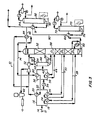
- Figure 1 is a schematic illustration of apparatus for carrying out a process according to the invention including a demethaniser, a fractionator and a return reflux line;
- Figure 2 is a schematic illustration of apparatus for carrying out a process according to the invention wherein a demethanised recycled absorption stream from a fractionator is initially cooled by a chiller and then a heat exchanger;
- Figure 3 is a schematic illustration of apparatus for carrying out a process according to the invention including a deethaniser fractionator and a depropaniser fractionator; and
- Figure 4 is a schematic illustration similar to Figure 3 but wherein a recycled depropanised product stream is initially cooled by a chiller and then a heat exchanger.
- Referring to Figure 1, natural gas enters gas
separator process apparatus 10 through aninlet 12 after having first been dehydrated. The gas passes toline 14 and is then divided into twoseparate streams gas stream 16 is cooled in a warm gas/gas exchanger 20 by cool residue gas in aline 22. Thegas stream 18 is cooled in areboiler 24 and alower side heater 26 through which demethaniser liquid flows vialines demethaniser column 32. - From the
exchanger 20 and thelower side heater 26, thecooled gas streams gas chiller 34 where the combined stream is further cooled by a refrigerant. After thechiller 34, the chilled stream is again separated into twostreams stream 36 is cooled in a cold gas/gas exchanger 40 by cold residue gas directly from the top of thedemethaniser column 32. This residue gas is generally at a temperature of -95.5°C (-140°F). As shown, this cold residue gas passes first through the cold gas/gas exchanger 40 before travelling through the warm gas/gas exchanger 20 via theline 22. Thestream 38 is cooled in anupper side heater 42 by demethanised liquid flowing through aline 44 from thedemethaniser column 32. This demethaniser liquid is generally at a temperature of -69.4°C (-125°F). Thecold gas streams high pressure separator 46 where the cooled inlet gas is separated into agas stream 48 and aliquid stream 50. Thegas stream 48, which by this time consists predominantly of the lighter methanes, ethanes and propanes, is expanded to reduce its pressure such as by amain expander 52 or across anexpansion valve 54. This expansion further cools the gas before it is fed into an upper region of thedemethaniser column 32. The condensedliquid stream 50 from thehigh pressure separator 46 is also expanded, thereby reducing its pressure, such as across anexpansion valve 56, before entering the side of thedemethaniser column 32. By this time, theliquid stream 50 consists predominantly of the heavier butanes, pentanes and their iso-components. - As liquid is fed to the
demethaniser column 32, it flows downward under the force of gravity. During its journey, the liquid is engaged by rising vapours which strip the methane from this liquid as it passes throughtrays 58 in thedemethaniser column 32. This stripping operation produces a demethanised end product which is removed from the bottom of thedemethaniser column 32 via aline 60. The rising methane vapours are generated from the heat obtained from theheat exchangers lines - A portion of the residue from the top of the
demethaniser column 32, where its temperature is approximately -95.5°C (-140°F), is conveyed to the cold gas/gas exchanger 40 and the warm, gas/gas exchanger 20. This cold residue cools theincoming gas streams main expander 52 and then by aturbo recompressor 62 after which it is cooled and transported elsewhere. The remaining portion of the cold residue from the top of thedemethaniser column 32 passes through aheat exchanger 64 which chills the recycled absorption stream in afeed line 66 that is recycled to the top of thedemethaniser column 32. - The
line 60 which forms an exit at the bottom of thedemethaniser column 32 transports the demethanised end product from thecolumn 32 to aheat exchanger 68 which heats this product before it enters afractionator 70. Thefractionator 70 acts as a distillation column or deethaniser and separates the lighter ethane component in this end product from the heavier propane, butanes, pentanes and their iso-components. The overhead product from thefractionator 70 exits through aline 72, whichline 72 contains essentially 100% of the ethane. Alower line 76, connected to the bottom of thefractionator 70, transports the deethanised product from thefractionator 70 through theexchanger 68 where this deethanised end product heats the incoming demethanised end product in theline 60. This deethaniser end product from thefractionator 70 is then recycled to the top of thedemethaniser column 32 via theline 66. The addition of this portion of the heavier deethanised product to thedemethaniser column 32 alters significantly the chemical equilibrium in the top of thecolumn 32. This causes the lighter vapourised ethane in the top of thecolumn 32 to become liquid and fall to the bottom of thecolumn 32 while a small amount of propane and heavier constituents are vapourised to make up the dew point in astream 74. Thefeed line 66 acts as an absorption medium which enhances the recovery of ethane at the expense of a small reduction in the recovery of propane and heavier components. - Another arrangement for the heat exchange of the recycled absorption in the
feed line 66 is shown in Figure 2. In this case, the recycledabsorption feed line 66 is first cooled by heat exchange in achiller 80 and then is further cooled in theexchanger 64 by a portion of the residue gas from thedemethaniser column 32. - Figure 3 illustrates another variation of this process which uses a depropanised product stream as the absorption medium for the
demethaniser column 32. In this case, the bottom deethanised product from thefractionator 70 flowing through aline 90 is heated in aheat exchanger 91 before entering a depropaniser orfractionator 92. Thefractionator 92 separates this incoming deethanised product into a top product that is predominantly propane and which leaves thefractionator 92 via aline 94, and a depropanised bottom product that consists of butanes and the heavier constituents and which leaves thefractionator 92 via aline 93. A portion of this heavier depropanised product in theline 93 is diverted to theline 66 where it is cooled in theheat exchanger 64 by the residue gases from thedemethaniser column 32 before entering the top of thedemethaniser column 32. This action causes the lighter vapourised ethane and propane in the top of thecolumn 32 to become liquid and fall to the bottom while a small amount of butane and heavier constituent are vapourised to make up the dew point in thestream 74. - Another arrangement of the recycle absorption medium is shown in Figure 4. In this case, the
recycle absorption stream 66 is first cooled by heat exchange in thechiller 80 with a refrigerant and then is further cooled in theheat exchanger 64 by heat exchange with a portion of the residue gas from thecolumn 32.
Claims (12)
Applications Claiming Priority (2)
| Application Number | Priority Date | Filing Date | Title |
|---|---|---|---|
| US847065 | 1986-04-01 | ||
| US06/847,065 US4698081A (en) | 1986-04-01 | 1986-04-01 | Process for separating hydrocarbon gas constituents utilizing a fractionator |
Publications (2)
| Publication Number | Publication Date |
|---|---|
| EP0240188A2 true EP0240188A2 (en) | 1987-10-07 |
| EP0240188A3 EP0240188A3 (en) | 1987-11-04 |
Family
ID=25299659
Family Applications (1)
| Application Number | Title | Priority Date | Filing Date |
|---|---|---|---|
| EP87302060A Withdrawn EP0240188A3 (en) | 1986-04-01 | 1987-03-10 | Process for separating hydrocarbon gas constituents |
Country Status (10)
| Country | Link |
|---|---|
| US (1) | US4698081A (en) |
| EP (1) | EP0240188A3 (en) |
| JP (1) | JPS62249936A (en) |
| AU (1) | AU7067587A (en) |
| BR (1) | BR8701436A (en) |
| DK (1) | DK151387A (en) |
| NO (1) | NO870349L (en) |
| NZ (1) | NZ218913A (en) |
| PT (1) | PT84594A (en) |
| ZA (1) | ZA869714B (en) |
Cited By (2)
| Publication number | Priority date | Publication date | Assignee | Title |
|---|---|---|---|---|
| EP0271658A3 (en) * | 1986-12-19 | 1988-10-12 | The M. W. Kellogg Company | Process for separation of hydrocarbon mixtures |
| WO2007144395A3 (en) * | 2006-06-16 | 2008-10-30 | Shell Int Research | Method and apparatus for treating a hydrocarbon stream |
Families Citing this family (42)
| Publication number | Priority date | Publication date | Assignee | Title |
|---|---|---|---|---|
| US4702819A (en) * | 1986-12-22 | 1987-10-27 | The M. W. Kellogg Company | Process for separation of hydrocarbon mixtures |
| GB8703751D0 (en) * | 1987-02-18 | 1987-03-25 | Costain Petrocarbon | Separation of hydrocarbon mixtures |
| US4923493A (en) * | 1988-08-19 | 1990-05-08 | Exxon Production Research Company | Method and apparatus for cryogenic separation of carbon dioxide and other acid gases from methane |
| US5375422A (en) * | 1991-04-09 | 1994-12-27 | Butts; Rayburn C. | High efficiency nitrogen rejection unit |
| US5152148A (en) * | 1991-06-14 | 1992-10-06 | Liquid Energy Corporation | Propane removal process |
| US5275005A (en) * | 1992-12-01 | 1994-01-04 | Elcor Corporation | Gas processing |
| US5325673A (en) * | 1993-02-23 | 1994-07-05 | The M. W. Kellogg Company | Natural gas liquefaction pretreatment process |
| US5442924A (en) * | 1994-02-16 | 1995-08-22 | The Dow Chemical Company | Liquid removal from natural gas |
| US5555748A (en) * | 1995-06-07 | 1996-09-17 | Elcor Corporation | Hydrocarbon gas processing |
| US5596883A (en) * | 1995-10-03 | 1997-01-28 | Air Products And Chemicals, Inc. | Light component stripping in plate-fin heat exchangers |
| US5685170A (en) * | 1995-11-03 | 1997-11-11 | Mcdermott Engineers & Constructors (Canada) Ltd. | Propane recovery process |
| DZ2535A1 (en) * | 1997-06-20 | 2003-01-08 | Exxon Production Research Co | Advanced process for liquefying natural gas. |
| US5953935A (en) * | 1997-11-04 | 1999-09-21 | Mcdermott Engineers & Constructors (Canada) Ltd. | Ethane recovery process |
| US5992175A (en) * | 1997-12-08 | 1999-11-30 | Ipsi Llc | Enhanced NGL recovery processes |
| MY115506A (en) | 1998-10-23 | 2003-06-30 | Exxon Production Research Co | Refrigeration process for liquefaction of natural gas. |
| MY117068A (en) | 1998-10-23 | 2004-04-30 | Exxon Production Research Co | Reliquefaction of pressurized boil-off from pressurized liquid natural gas |
| US6116050A (en) * | 1998-12-04 | 2000-09-12 | Ipsi Llc | Propane recovery methods |
| US6244070B1 (en) | 1999-12-03 | 2001-06-12 | Ipsi, L.L.C. | Lean reflux process for high recovery of ethane and heavier components |
| US6354105B1 (en) | 1999-12-03 | 2002-03-12 | Ipsi L.L.C. | Split feed compression process for high recovery of ethane and heavier components |
| MY122625A (en) | 1999-12-17 | 2006-04-29 | Exxonmobil Upstream Res Co | Process for making pressurized liquefied natural gas from pressured natural gas using expansion cooling |
| US7216507B2 (en) * | 2004-07-01 | 2007-05-15 | Ortloff Engineers, Ltd. | Liquefied natural gas processing |
| RU2272973C1 (en) * | 2004-09-24 | 2006-03-27 | Салават Зайнетдинович Имаев | Method of low-temperature gas separation |
| KR101407771B1 (en) * | 2006-06-02 | 2014-06-16 | 오르트로프 엔지니어스, 리미티드 | Liquefied natural gas processing |
| EP2054685A2 (en) * | 2006-08-23 | 2009-05-06 | Shell Internationale Research Maatschappij B.V. | Method and apparatus for treating a hydrocarbon stream |
| US8590340B2 (en) * | 2007-02-09 | 2013-11-26 | Ortoff Engineers, Ltd. | Hydrocarbon gas processing |
| US9869510B2 (en) * | 2007-05-17 | 2018-01-16 | Ortloff Engineers, Ltd. | Liquefied natural gas processing |
| US20090282865A1 (en) | 2008-05-16 | 2009-11-19 | Ortloff Engineers, Ltd. | Liquefied Natural Gas and Hydrocarbon Gas Processing |
| US8434325B2 (en) | 2009-05-15 | 2013-05-07 | Ortloff Engineers, Ltd. | Liquefied natural gas and hydrocarbon gas processing |
| US20100287982A1 (en) | 2009-05-15 | 2010-11-18 | Ortloff Engineers, Ltd. | Liquefied Natural Gas and Hydrocarbon Gas Processing |
| US9021832B2 (en) * | 2010-01-14 | 2015-05-05 | Ortloff Engineers, Ltd. | Hydrocarbon gas processing |
| AU2011261670B2 (en) | 2010-06-03 | 2014-08-21 | Uop Llc | Hydrocarbon gas processing |
| TWI510436B (en) | 2012-12-18 | 2015-12-01 | Invista Tech Sarl | Hydrogen cyanide production with treated natural gas as source of methane-containing feedstock |
| EP2935114A1 (en) | 2012-12-18 | 2015-10-28 | Invista Technologies S.à.r.l. | Hydrogen cyanide production with controlled feedstock composition |
| CA2942675C (en) | 2014-03-14 | 2024-01-09 | Lummus Technology Inc. | Process and apparatus for heavy hydrocarbon removal from lean natural gas before liquefaction |
| US10551119B2 (en) | 2016-08-26 | 2020-02-04 | Ortloff Engineers, Ltd. | Hydrocarbon gas processing |
| US10533794B2 (en) | 2016-08-26 | 2020-01-14 | Ortloff Engineers, Ltd. | Hydrocarbon gas processing |
| US10551118B2 (en) | 2016-08-26 | 2020-02-04 | Ortloff Engineers, Ltd. | Hydrocarbon gas processing |
| US11402155B2 (en) | 2016-09-06 | 2022-08-02 | Lummus Technology Inc. | Pretreatment of natural gas prior to liquefaction |
| US11428465B2 (en) | 2017-06-01 | 2022-08-30 | Uop Llc | Hydrocarbon gas processing |
| US11543180B2 (en) | 2017-06-01 | 2023-01-03 | Uop Llc | Hydrocarbon gas processing |
| AR121085A1 (en) | 2020-01-24 | 2022-04-13 | Lummus Technology Inc | PROCESS FOR RECOVERY OF HYDROCARBONS FROM MULTIPLE BACKFLOW STREAMS |
| CN114263511B (en) * | 2021-12-21 | 2024-01-26 | 西安石油大学 | Light hydrocarbon separation coupled parallel recuperation organic Rankine cycle power generation system using LNG cold energy |
Family Cites Families (13)
| Publication number | Priority date | Publication date | Assignee | Title |
|---|---|---|---|---|
| US2627318A (en) * | 1949-08-08 | 1953-02-03 | Socony Vacuum Oil Co Inc | Refrigeration method of recovering hydrocarbons from gas mixtures |
| US3398543A (en) * | 1966-03-23 | 1968-08-27 | American Mach & Foundry | Hydrocarbon gas liquefaction by admixed gas-liquid expansion and heat exchange |
| US3849096A (en) * | 1969-07-07 | 1974-11-19 | Lummus Co | Fractionating lng utilized as refrigerant under varying loads |
| US4171964A (en) * | 1976-06-21 | 1979-10-23 | The Ortloff Corporation | Hydrocarbon gas processing |
| US4278457A (en) * | 1977-07-14 | 1981-07-14 | Ortloff Corporation | Hydrocarbon gas processing |
| US4162273A (en) * | 1978-01-10 | 1979-07-24 | Phillips Petroleum Company | Alkaline treatment of liquid propane containing HF |
| US4235613A (en) * | 1979-05-29 | 1980-11-25 | Atlantic Richfield Company | Preparation of sales gas |
| FR2458525A1 (en) * | 1979-06-06 | 1981-01-02 | Technip Cie | IMPROVED PROCESS FOR THE PRODUCTION OF ETHYLENE AND ETHYLENE PRODUCTION PLANT COMPRISING THE APPLICATION OF SAID METHOD |
| US4370156A (en) * | 1981-05-29 | 1983-01-25 | Standard Oil Company (Indiana) | Process for separating relatively pure fractions of methane and carbon dioxide from gas mixtures |
| US4410342A (en) * | 1982-05-24 | 1983-10-18 | United States Riley Corporation | Method and apparatus for separating a liquid product from a hydrocarbon-containing gas |
| US4464190A (en) * | 1982-08-18 | 1984-08-07 | Gulsby Engineering, Inc. | Hydrocarbon gas process |
| US4453958A (en) * | 1982-11-24 | 1984-06-12 | Gulsby Engineering, Inc. | Greater design capacity-hydrocarbon gas separation process |
| US4596588A (en) * | 1985-04-12 | 1986-06-24 | Gulsby Engineering Inc. | Selected methods of reflux-hydrocarbon gas separation process |
-
1986
- 1986-04-01 US US06/847,065 patent/US4698081A/en not_active Expired - Lifetime
- 1986-12-29 ZA ZA869714A patent/ZA869714B/en unknown
-
1987
- 1987-01-13 NZ NZ218913A patent/NZ218913A/en unknown
- 1987-01-27 JP JP62015340A patent/JPS62249936A/en active Pending
- 1987-01-28 NO NO870349A patent/NO870349L/en unknown
- 1987-03-10 EP EP87302060A patent/EP0240188A3/en not_active Withdrawn
- 1987-03-25 DK DK151387A patent/DK151387A/en not_active IP Right Cessation
- 1987-03-26 AU AU70675/87A patent/AU7067587A/en not_active Abandoned
- 1987-03-30 BR BR8701436A patent/BR8701436A/en unknown
- 1987-03-31 PT PT84594A patent/PT84594A/en unknown
Cited By (2)
| Publication number | Priority date | Publication date | Assignee | Title |
|---|---|---|---|---|
| EP0271658A3 (en) * | 1986-12-19 | 1988-10-12 | The M. W. Kellogg Company | Process for separation of hydrocarbon mixtures |
| WO2007144395A3 (en) * | 2006-06-16 | 2008-10-30 | Shell Int Research | Method and apparatus for treating a hydrocarbon stream |
Also Published As
| Publication number | Publication date |
|---|---|
| NO870349D0 (en) | 1987-01-28 |
| NZ218913A (en) | 1988-03-30 |
| DK151387D0 (en) | 1987-03-25 |
| EP0240188A3 (en) | 1987-11-04 |
| JPS62249936A (en) | 1987-10-30 |
| PT84594A (en) | 1987-04-01 |
| BR8701436A (en) | 1988-01-05 |
| US4698081A (en) | 1987-10-06 |
| NO870349L (en) | 1987-10-02 |
| DK151387A (en) | 1987-10-02 |
| AU7067587A (en) | 1987-10-08 |
| ZA869714B (en) | 1987-08-26 |
Similar Documents
| Publication | Publication Date | Title |
|---|---|---|
| EP0240188A2 (en) | Process for separating hydrocarbon gas constituents | |
| US4687499A (en) | Process for separating hydrocarbon gas constituents | |
| EP0377949B1 (en) | Process and apparatus for c2 recovery | |
| USRE33408E (en) | Process for LPG recovery | |
| US4507133A (en) | Process for LPG recovery | |
| JP5997798B2 (en) | Nitrogen removal by isobaric open frozen natural gas liquid recovery | |
| CA2805272C (en) | Methods and systems for recovering liquified petroleum gas from natural gas | |
| US5685170A (en) | Propane recovery process | |
| US6516631B1 (en) | Hydrocarbon gas processing | |
| US5890377A (en) | Hydrocarbon gas separation process | |
| US4504295A (en) | Nitrogen rejection from natural gas integrated with NGL recovery | |
| US4710213A (en) | Process for separating CO2 from a gaseous mixture | |
| US3393527A (en) | Method of fractionating natural gas to remove heavy hydrocarbons therefrom | |
| US6311516B1 (en) | Process and apparatus for C3 recovery | |
| CA1108522A (en) | Cryogenic recovery of liquids from refinery off-gases | |
| US4356014A (en) | Cryogenic recovery of liquids from refinery off-gases | |
| US4456461A (en) | Separation of low boiling constituents from a mixed gas | |
| WO2004057253A2 (en) | Lean reflux-high hydrocarbon recovery process | |
| US4770683A (en) | Distillation process with high thermo-dynamic efficiencies | |
| EP3540028B1 (en) | A method to recover lpg and condensates from refineries fuel gas streams | |
| JP2007524578A (en) | Hydrocarbon gas treatment | |
| US3595782A (en) | Method for separating crabon dioxide from hydrocarbons | |
| US4444577A (en) | Cryogenic gas processing | |
| US8093440B2 (en) | Process and apparatus for C2 recovery | |
| US6931889B1 (en) | Cryogenic process for increased recovery of hydrogen |
Legal Events
| Date | Code | Title | Description |
|---|---|---|---|
| PUAI | Public reference made under article 153(3) epc to a published international application that has entered the european phase |
Free format text: ORIGINAL CODE: 0009012 |
|
| PUAL | Search report despatched |
Free format text: ORIGINAL CODE: 0009013 |
|
| AK | Designated contracting states |
Kind code of ref document: A2 Designated state(s): BE DE ES FR GB GR IT NL SE |
|
| AK | Designated contracting states |
Kind code of ref document: A3 Designated state(s): BE DE ES FR GB GR IT NL SE |
|
| 17P | Request for examination filed |
Effective date: 19880226 |
|
| 17Q | First examination report despatched |
Effective date: 19881018 |
|
| STAA | Information on the status of an ep patent application or granted ep patent |
Free format text: STATUS: THE APPLICATION IS DEEMED TO BE WITHDRAWN |
|
| 18D | Application deemed to be withdrawn |
Effective date: 19890301 |
|
| RIN1 | Information on inventor provided before grant (corrected) |
Inventor name: AGHILI, HAFEZ KERMANI |