EP0240194A1 - Expenseur des faisceaux optiques - Google Patents
Expenseur des faisceaux optiques Download PDFInfo
- Publication number
- EP0240194A1 EP0240194A1 EP19870302185 EP87302185A EP0240194A1 EP 0240194 A1 EP0240194 A1 EP 0240194A1 EP 19870302185 EP19870302185 EP 19870302185 EP 87302185 A EP87302185 A EP 87302185A EP 0240194 A1 EP0240194 A1 EP 0240194A1
- Authority
- EP
- European Patent Office
- Prior art keywords
- beam expander
- materials
- lens element
- temperature
- respect
- Prior art date
- Legal status (The legal status is an assumption and is not a legal conclusion. Google has not performed a legal analysis and makes no representation as to the accuracy of the status listed.)
- Granted
Links
Images
Classifications
-
- G—PHYSICS
- G02—OPTICS
- G02B—OPTICAL ELEMENTS, SYSTEMS OR APPARATUS
- G02B27/00—Optical systems or apparatus not provided for by any of the groups G02B1/00 - G02B26/00, G02B30/00
- G02B27/09—Beam shaping, e.g. changing the cross-sectional area, not otherwise provided for
- G02B27/0938—Using specific optical elements
- G02B27/095—Refractive optical elements
- G02B27/0955—Lenses
-
- G—PHYSICS
- G02—OPTICS
- G02B—OPTICAL ELEMENTS, SYSTEMS OR APPARATUS
- G02B13/00—Optical objectives specially designed for the purposes specified below
- G02B13/14—Optical objectives specially designed for the purposes specified below for use with infrared or ultraviolet radiation
-
- G—PHYSICS
- G02—OPTICS
- G02B—OPTICAL ELEMENTS, SYSTEMS OR APPARATUS
- G02B13/00—Optical objectives specially designed for the purposes specified below
- G02B13/22—Telecentric objectives or lens systems
-
- G—PHYSICS
- G02—OPTICS
- G02B—OPTICAL ELEMENTS, SYSTEMS OR APPARATUS
- G02B27/00—Optical systems or apparatus not provided for by any of the groups G02B1/00 - G02B26/00, G02B30/00
- G02B27/09—Beam shaping, e.g. changing the cross-sectional area, not otherwise provided for
Definitions
- This invention concerns improvements in or relating to optical beam expanders.
- Some optical systems require optical beam expansion such that the diameter of a beam of electromagnetic radiation is effectively increased. Frequently the beam is the output of a laser system. Gains which can be achieved by beam expansion are that the beam divergence is reduced by the magnification ratio and that the beam flux per unit area is similarly reduced.
- An example of a beam expansion system is disclosed in United States Patent No. 4,475,793. That system includes a basically known form of afocal refractive beam expander consisting of a negatively powered lens element air spaced by a fixed distance from a positively powered lens element and arranged so that the negative element diverges a narrow substantially parallel sided beam and the positive element returns the beam to substantially parallelism but at an increased diameter.
- a beam expander has lens elements of a material whose refractive index varies substantially with temperature, then the device is correspondingly temperature sensitive.
- the refracting lens elements are made of germanium, which is commonly used for infra-red wavelengths but has a relatively large rate of change of refractive index with respect to temperature, then the beam expander while satisfactorily operative to effect a required afocal beam expansion at one temperature will not have the same effect at a different temperature and afocality will be lost.
- the change of refractive index with temperature can be compensated by modifying the central air space between the lens elements in step with the temperature change, but this introduces the generally undesirable requirement of movable parts with consequential complication.
- the present invention broadly provides an optical substantially afocal beam expander having spaced negative and positive lens components employing different materials having respective refractive index changes with respect to temperature such that the effect of a temperature change on one component is at least partially compensated by the effect of the temperature change on the other component whereby the beam expander is substantially athermalised with respect to afocality.
- an optical substantially afocal beam expander comprising a lens element of negative power of a first material spaced from a lens element of a positive power of a second material different from the first, in which the respective coefficients of refractive index change with respect to temperature of the first and second materials are related in a manner such that the beam expander is substantially athermalised with respect to afocality.
- the magnification and the refractive index coefficients of the two materials preferably substantially satisfy (at a design temperature) the relationship:-
- the magnification and the constringences of the two materials preferably additionally substantially satisfy (at the design temperature) the relationship:-
- said lens element of negative power may be a back element of meniscus shape convex to the rear
- said lens element of positive power may be a front element of meniscus shape convex to the front or convex to the rear.
- the beam expander may be designed for operation with infra-red radiation, the materials of the lens components or elements then being infra-red transmitting materials, i.e. materials having a useful spectral bandpass to radiation of the operative infra-red wavelength or wavelengths.
- the materials may, for example, be transmissive to thermal infra-red radiation in which case the constringence value 'V' is generally given by:
- said first and second materials may, for example, be germanium and zinc selenide respectively.
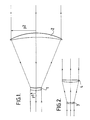
- the beam expander of Figure 1 consists of a rear singlet lens element 1 of negative power spaced from a front singlet lens element 2 of positive power as in a Galilean telescope.
- the negative rear lens element 1 causes divergence of an incident parallel sided beam and the positive front lens element 2 returns the beam to parallel sided form but at an increased diameter relative to the incident beam.
- the lens elements 1 and 2 have a common focal point (which is virtual so that undesirable energy concentration with a high energy laser beam is avoided).
- a narrow incident beam usually from a laser, is expanded to a relatively broad emergent beam.
- the extent of the expansion i.e. the magnification, is the ratio of the diameters of the incident and outgoing beams, or, expressed otherwise, the ratio of the image ray height 'y2' at the positive lens elements to the image ray height 'y1' at the negative lens element.
- the lens elements 1 and 2 are mounted in a suitable housing or cell (not shown).
- the magnification of the afocal beam expander is equal to the ratio of the focal lengths of the individual lens elements 1 and 2. Each focal length is approximately inversely proportional to the term '(n-1)', where 'n' is the refractive index of the material of the respective lens element.
- the ratio of the powers determining that magnification power being the reciprocal of focal length
- the required ratio of the coefficients of change of refractive index with respect to temperature of the two materials i.e. if materials having coefficients whose ratio accords with the given power ratio (and hence magnification) are chosen, or conversely if a magnification and power ratio are selected to accord with the ratio of coefficients of suitable available materials.
- ⁇ K CHR and ⁇ K TH are each generally zero and for an afocal system K T is also zero since the full system has no focussing action and therefore no overall power.
- Relationship B) is applicable with a polychromatic beam, but if the beam to be expanded is of effectively monochromatic radiation, for example from a laser source, there is no need to limit the choice of materials to their chromatic dispersions, and compliance with relationship B) therefore becomes unnecessary.
- athermalisation can be achieved if the relationship between the magnification and the refractive index coefficients of the two materials satisfies A), i.e.:-
- a particular example of afocal beam expander for use with a laser beam of 10.6 microns wavelength has numerical data as follows. It is of the form shown in Figure 1 with a negative back element 1 of meniscus shape convex to the rear and a positive front element 2 of meniscus shape convex to the front.
- the refracting surfaces, indicated from the back to the front as R1 to R4, are all of spherical curvature, and the dimensional units are millimetres (but the values are relative and can be scaled accordingly).
- This example of expander provides a magnification of 4.3 at 20°C, the focal length of the negative element 1 being -28.985 and the focal length of the positive element 2 being 125.000.
- the negative element 1 is of Germanium and the positive element 2 is of zinc selenide, these materials having refractive index 'n' and constringence 'V' values at 20°C, and coefficients of change of refractive index with respect to temperature (dn/dT) values as follows:-
- the design of this example is diffraction limited for a 20 mm diameter entrance beam.
- the lens elements are air spaced and ideally this space should have zero or slightly negative expansion with temperature increase. In practice this is effectively achieved by having a low expansion lens cell material for the mount.
- magnification value calculated from relationship A) above works out at about 3.1 as against the actual magnification of 4.3, i.e. a departure of about +30%.
- this extent of athermalisation with respect to afocality is sufficient for the requirements of the system in which this example of beam expander is to be used and enables the example to be diffraction limited over a range of temperature variation of about ⁇ 36°C, whereas a corresponding beam expander with both elements of germanium would be diffraction limited over a temperature variation range of only about ⁇ 4°C.
- the departure from the theoretical value according to relationship A) may be more, for example 50%, or less (and/or of opposite sign) than with the present example in order to effect substantial athermalisation, i.e. athermalisation to an extent which maintains substantial afocality sufficiently closely with variation of temperature to meet the requirements of the system in which the expander is used.
- substantially afocal beam expander is schematically shown in Figure 2. It has a negatively powered back element 3 of meniscus shape convex to the rear and a positively powered front element 4 of meniscus shape also convex to the rear.
- An example in accordance with the Figure 2 embodiment having an germanium negative back element 3 air spaced from a zinc selenide positive front element 4 has numerical values as follows, the refracting surfaces again being all of spherical curvature and indicated from the back to the front as R1 to R4, and the dimensional units being millimetres (but scaleable).
- This example of expander provides a magnification of 2.2 at 20°C, i.e. a departure of about -30% from calculated 3.1 value given by relationship A) for germanium and zinc selenide.
- Example II the negative element 3 has focal length of -30.07 and the positive element 4 has a focal length of 69.72.
- the example is not precisely afocal and the separation between the lens elements, i.e. the axial spacing of surfaces R2 and R3, would need to be set to 40.88 to render it paraxially afocal.
- This example also has some residual aberration to balance aberration in the rest of the optical system in which it is used. To balance the aberration within the beam expander the axial spacing of surfaces R2 and R3 would need to be set to 39.1.
- Example II thus illustrates that a beam expander in accordance with the invention need not necessarily be exactly afocal, for example if the system in which it is used requires some departure from precise afocality. It will be understood that such an expander can still be substantially athermalised with respect to afocality (i.e. with respect to focus of which afocality is a particular condition).
- Example II also illustrates that a beam expander in accordance with the invention need not necessarily be self-balanced for aberration but may have residual aberration, for example to balance aberration from the rest of the system containing the beam expander. It will thus be understood that the terms K T , ⁇ K CHR and ⁇ K TH may not all be actually zero.
- the medium separating the lens elements is conveniently air some other gas could be employed if desired, and although surfaces of spherical curvature are generally preferable for ease of manufacture one or more aspheric surfaces could be provided if required. Further, as previously indicated a polychromatic beam expander athermalised for afocality can be provided if relationship B) above is satisfied in addition to relationship A).
- a beam expander with spaced negative and positive lens components constituted by single lens elements is a very simple and convenient arrangement which can be substantially athermalised with respect to afocality, i.e. substantially to maintain the afocal or nearly afocal focus condition despite temperature changes, as described above. It will be understood, however, that such arrangement with two single elements only cannot also be athermalised to maintain magnification, i.e. to effect the same magnification despite changes in temperature. To achieve this it would generally be necessary to athermalise each of the negative and positive components separately and independently so that each by itself satisfies the three previously mentioned conditions. This would normally require the provision of elements of at least three different materials in each component with the consequential complexity and expense.
- change of magnification with temperature can to some extent be alleviated by having more than one lens element in one or both of the negative and positive components whilst still applying the principle described above of employing different materials having respective refractive index changes with respect to temperature such that the effect of temperature change on the negative component is at least partially compensated by the effect of temperature change on the positive component so as substantially to athermalise the beam expander with respect to afocality.
- a group of at least two lens elements constituting a component means, of course, that the power or focal length of that component is determined by further optical considerations but the principle of effectively balancing the effect of temperature change on one component against the effect on the other component to maintain substantial afocality can still apply. Therefore, although single element components may generally be preferable for their simplicity, a substantially afocal beam expander according to the invention could have a negative and/or a positive component constituted by at least two lens elements, which in the one component may be of the same or of different materials and may be separate or cemented together.
Landscapes
- Physics & Mathematics (AREA)
- General Physics & Mathematics (AREA)
- Optics & Photonics (AREA)
- Health & Medical Sciences (AREA)
- Toxicology (AREA)
- Lenses (AREA)
- Glass Compositions (AREA)
- Laser Surgery Devices (AREA)
- Surgical Instruments (AREA)
- Lens Barrels (AREA)
- Crystals, And After-Treatments Of Crystals (AREA)
Priority Applications (1)
| Application Number | Priority Date | Filing Date | Title |
|---|---|---|---|
| AT87302185T ATE78106T1 (de) | 1986-04-03 | 1987-03-13 | Optischer strahlaufweiter. |
Applications Claiming Priority (2)
| Application Number | Priority Date | Filing Date | Title |
|---|---|---|---|
| GB8608130 | 1986-04-03 | ||
| GB8608130 | 1986-04-03 |
Publications (2)
| Publication Number | Publication Date |
|---|---|
| EP0240194A1 true EP0240194A1 (fr) | 1987-10-07 |
| EP0240194B1 EP0240194B1 (fr) | 1992-07-08 |
Family
ID=10595603
Family Applications (1)
| Application Number | Title | Priority Date | Filing Date |
|---|---|---|---|
| EP87302185A Expired - Lifetime EP0240194B1 (fr) | 1986-04-03 | 1987-03-13 | Expenseur des faisceaux optiques |
Country Status (5)
| Country | Link |
|---|---|
| US (1) | US4834472A (fr) |
| EP (1) | EP0240194B1 (fr) |
| AT (1) | ATE78106T1 (fr) |
| DE (1) | DE3780196T2 (fr) |
| GB (1) | GB2194072B (fr) |
Cited By (5)
| Publication number | Priority date | Publication date | Assignee | Title |
|---|---|---|---|---|
| EP0480805A1 (fr) * | 1990-10-09 | 1992-04-15 | Thomson-Trt Defense | Systèmes d'objectifs à athermalisation optique |
| EP0721113A3 (fr) * | 1995-01-04 | 1997-01-02 | Hughes Aircraft Co | Surface optique ellipsoidale réfractive aberration sphérique |
| WO1999059015A1 (fr) * | 1998-05-08 | 1999-11-18 | Pilkington Pe Limited | Systeme d'objectif a double champ visuel pour l'infrarouge |
| FR2910978A1 (fr) * | 2006-12-28 | 2008-07-04 | Commissariat Energie Atomique | Systeme optique de traitement d'un faisceau lumineux |
| EP2790050A1 (fr) | 2013-04-11 | 2014-10-15 | asphericon GmbH | Dispositif de formation de faisceaux réfractifs |
Families Citing this family (8)
| Publication number | Priority date | Publication date | Assignee | Title |
|---|---|---|---|---|
| US5225928A (en) * | 1991-10-07 | 1993-07-06 | Spectra-Physics Laserplane, Inc. | Focus compensating lens for use in extreme temperatures |
| US5214532A (en) * | 1992-04-29 | 1993-05-25 | The United States Of America As Represented By The Secretary Of The Army | Afocal objective lens |
| JP3315176B2 (ja) * | 1993-01-29 | 2002-08-19 | オリンパス光学工業株式会社 | 逆ガリレオ式ファインダー光学系 |
| US8274743B2 (en) * | 2010-04-08 | 2012-09-25 | Scaggs Michael J | Thermally compensating lens for high power lasers |
| KR101783981B1 (ko) * | 2011-03-09 | 2017-10-10 | 한화테크윈 주식회사 | 적외선 광학 렌즈계 |
| DE102012108214B4 (de) | 2012-09-04 | 2014-04-30 | Highyag Lasertechnologie Gmbh | Optik mit stabilisierter Fokuslage für Hochleistungslaser |
| CN106415351B (zh) * | 2014-08-07 | 2018-07-03 | 大族激光科技产业集团股份有限公司 | 远红外成像透镜组、物镜及探测仪 |
| CN107144946A (zh) * | 2017-05-27 | 2017-09-08 | 中国科学院上海技术物理研究所 | 一种大口径消热差长波红外镜头 |
Citations (2)
| Publication number | Priority date | Publication date | Assignee | Title |
|---|---|---|---|---|
| US3817604A (en) * | 1973-01-03 | 1974-06-18 | Atomic Energy Commission | Method of focusing a high-powered laser beam |
| GB1530066A (en) * | 1977-06-09 | 1978-10-25 | Philips Electronic Associated | Infra-red reversible telescope |
Family Cites Families (10)
| Publication number | Priority date | Publication date | Assignee | Title |
|---|---|---|---|---|
| GB561503A (en) * | 1942-08-11 | 1944-05-23 | Combined Optical Ind Ltd | Improvements in optical systems using plastic lenses |
| US2453218A (en) * | 1946-03-05 | 1948-11-09 | Polaroid Corp | Image forming optical lens system athermalized for focal point |
| GB1559514A (en) * | 1976-10-02 | 1980-01-23 | Pilkington Perkin Elmer Ltd | Infra-red zoom lenses |
| GB2071353B (en) * | 1980-03-05 | 1984-02-08 | Barr & Stroud Ltd | Telescope objective system |
| US4469396A (en) * | 1980-10-08 | 1984-09-04 | Barr & Stroud Limited | Afocal dual magnification refractor telescopes |
| US4475793A (en) * | 1982-06-01 | 1984-10-09 | Texas Instruments Incorporated | Integrated optical beam expander |
| GB2121211B (en) * | 1982-06-02 | 1985-12-18 | Barr & Stroud Ltd | Athermal infrared objective lens systems |
| GB2138591B (en) * | 1983-04-16 | 1986-05-08 | Barr & Stroud Ltd | Infrared objective zoom lens assembly |
| JPS59211013A (ja) * | 1983-05-16 | 1984-11-29 | Fuji Photo Optical Co Ltd | 温度補償を施したプラスチツク対物レンズ系 |
| GB8417993D0 (en) * | 1984-07-14 | 1984-08-15 | Pilkington Perkin Elmer Ltd | Infra-red lenses |
-
1987
- 1987-03-13 EP EP87302185A patent/EP0240194B1/fr not_active Expired - Lifetime
- 1987-03-13 DE DE8787302185T patent/DE3780196T2/de not_active Expired - Lifetime
- 1987-03-13 AT AT87302185T patent/ATE78106T1/de not_active IP Right Cessation
- 1987-03-13 GB GB8706023A patent/GB2194072B/en not_active Expired - Lifetime
- 1987-03-17 US US07/027,007 patent/US4834472A/en not_active Expired - Fee Related
Patent Citations (2)
| Publication number | Priority date | Publication date | Assignee | Title |
|---|---|---|---|---|
| US3817604A (en) * | 1973-01-03 | 1974-06-18 | Atomic Energy Commission | Method of focusing a high-powered laser beam |
| GB1530066A (en) * | 1977-06-09 | 1978-10-25 | Philips Electronic Associated | Infra-red reversible telescope |
Non-Patent Citations (1)
| Title |
|---|
| OPTICAL ENGINEERING, vol. 19, no. 6, November/December 1980, pages 888-893, Bellingham, US; T.H. JAMIESON "Refracting afocal systems in thermal imagers" * |
Cited By (11)
| Publication number | Priority date | Publication date | Assignee | Title |
|---|---|---|---|---|
| EP0480805A1 (fr) * | 1990-10-09 | 1992-04-15 | Thomson-Trt Defense | Systèmes d'objectifs à athermalisation optique |
| EP0721113A3 (fr) * | 1995-01-04 | 1997-01-02 | Hughes Aircraft Co | Surface optique ellipsoidale réfractive aberration sphérique |
| US5654831A (en) * | 1995-01-04 | 1997-08-05 | Hughes Electronics | Refractive ellipsoid optical surface without spherical aberration |
| WO1999059015A1 (fr) * | 1998-05-08 | 1999-11-18 | Pilkington Pe Limited | Systeme d'objectif a double champ visuel pour l'infrarouge |
| US6424460B1 (en) | 1998-05-08 | 2002-07-23 | Pilkington Pe Limited | Dual field-of-view objects system for the infrared |
| FR2910978A1 (fr) * | 2006-12-28 | 2008-07-04 | Commissariat Energie Atomique | Systeme optique de traitement d'un faisceau lumineux |
| WO2008080916A1 (fr) * | 2006-12-28 | 2008-07-10 | Commissariat A L'energie Atomique | Systeme optique de traitement d'un faisceau lumineux |
| US7952816B2 (en) | 2006-12-28 | 2011-05-31 | Commissariat A L'energie Atomique | Optical system for processing a light beam |
| EP2790050A1 (fr) | 2013-04-11 | 2014-10-15 | asphericon GmbH | Dispositif de formation de faisceaux réfractifs |
| DE102013206394A1 (de) | 2013-04-11 | 2014-10-16 | Asphericon Gmbh | Refraktiver Strahlformer |
| US9547177B2 (en) | 2013-04-11 | 2017-01-17 | Asphericon Gmbh | Refractive beam shaper |
Also Published As
| Publication number | Publication date |
|---|---|
| DE3780196D1 (de) | 1992-08-13 |
| DE3780196T2 (de) | 1992-12-24 |
| US4834472A (en) | 1989-05-30 |
| GB2194072A (en) | 1988-02-24 |
| GB8706023D0 (en) | 1987-04-15 |
| ATE78106T1 (de) | 1992-07-15 |
| EP0240194B1 (fr) | 1992-07-08 |
| GB2194072B (en) | 1990-03-21 |
Similar Documents
| Publication | Publication Date | Title |
|---|---|---|
| US5268790A (en) | Zoom lens employing refractive and diffractive optical elements | |
| EP0601873B1 (fr) | Prisme achromatique et apochromatique utilisant des prismes et des réseaux de diffraction | |
| US4331390A (en) | Monocentric optical systems | |
| US5691847A (en) | Athermalized and achromatized optical systems employing diffractive optical element | |
| US4679891A (en) | Infra-red lenses | |
| EP0240194B1 (fr) | Expenseur des faisceaux optiques | |
| US4714307A (en) | Catadioptric infrared lenses | |
| US4802717A (en) | Infrared afocal zoom telescope | |
| US5229880A (en) | Three field of view refractive afocal telescope | |
| US4397520A (en) | Afocal refractor telescopes | |
| US4479695A (en) | Afocal refractor telescopes | |
| US5000548A (en) | Microscope objective | |
| US4676581A (en) | Infra-red lenses | |
| US4398786A (en) | Collimation lens system | |
| GB2136149A (en) | High Magnification Afocal Infrared Telescopes | |
| US5946141A (en) | Apochromatic lens system for relaying laser beam waists | |
| CA1202509A (fr) | Objectif grand angulaire du type a retrofocalisation | |
| CA2603880A1 (fr) | Objectif de camera numerique compact et leger | |
| GB2269024A (en) | Optical system having at least one tilted Mangin mirror | |
| GB2068585A (en) | Single Element Optical System | |
| RU2613483C1 (ru) | Атермализованный объектив для ИК-области спектра | |
| US4190324A (en) | Achromatic objective lens | |
| US4362366A (en) | Focal length extender | |
| US4801183A (en) | Infra-red optical systems | |
| GB2072871A (en) | Afocal refractor telescopes |
Legal Events
| Date | Code | Title | Description |
|---|---|---|---|
| PUAI | Public reference made under article 153(3) epc to a published international application that has entered the european phase |
Free format text: ORIGINAL CODE: 0009012 |
|
| AK | Designated contracting states |
Kind code of ref document: A1 Designated state(s): AT BE CH DE ES FR GR IT LI NL SE |
|
| 17P | Request for examination filed |
Effective date: 19880326 |
|
| 17Q | First examination report despatched |
Effective date: 19891117 |
|
| GRAA | (expected) grant |
Free format text: ORIGINAL CODE: 0009210 |
|
| ITF | It: translation for a ep patent filed | ||
| AK | Designated contracting states |
Kind code of ref document: B1 Designated state(s): AT BE CH DE ES FR GR IT LI NL SE |
|
| PG25 | Lapsed in a contracting state [announced via postgrant information from national office to epo] |
Ref country code: NL Effective date: 19920708 Ref country code: LI Effective date: 19920708 Ref country code: GR Free format text: LAPSE BECAUSE OF FAILURE TO SUBMIT A TRANSLATION OF THE DESCRIPTION OR TO PAY THE FEE WITHIN THE PRESCRIBED TIME-LIMIT Effective date: 19920708 Ref country code: CH Effective date: 19920708 Ref country code: BE Effective date: 19920708 Ref country code: AT Effective date: 19920708 |
|
| REF | Corresponds to: |
Ref document number: 78106 Country of ref document: AT Date of ref document: 19920715 Kind code of ref document: T |
|
| RIN1 | Information on inventor provided before grant (corrected) |
Inventor name: PALMER, JOHN MALCOLM |
|
| REF | Corresponds to: |
Ref document number: 3780196 Country of ref document: DE Date of ref document: 19920813 |
|
| ET | Fr: translation filed | ||
| REG | Reference to a national code |
Ref country code: CH Ref legal event code: PL |
|
| PG25 | Lapsed in a contracting state [announced via postgrant information from national office to epo] |
Ref country code: ES Free format text: LAPSE BECAUSE OF FAILURE TO SUBMIT A TRANSLATION OF THE DESCRIPTION OR TO PAY THE FEE WITHIN THE PRESCRIBED TIME-LIMIT Effective date: 19921019 |
|
| NLV1 | Nl: lapsed or annulled due to failure to fulfill the requirements of art. 29p and 29m of the patents act | ||
| PLBE | No opposition filed within time limit |
Free format text: ORIGINAL CODE: 0009261 |
|
| STAA | Information on the status of an ep patent application or granted ep patent |
Free format text: STATUS: NO OPPOSITION FILED WITHIN TIME LIMIT |
|
| 26N | No opposition filed | ||
| EAL | Se: european patent in force in sweden |
Ref document number: 87302185.1 |
|
| PGFP | Annual fee paid to national office [announced via postgrant information from national office to epo] |
Ref country code: SE Payment date: 19950315 Year of fee payment: 9 |
|
| PG25 | Lapsed in a contracting state [announced via postgrant information from national office to epo] |
Ref country code: SE Effective date: 19960314 |
|
| EUG | Se: european patent has lapsed |
Ref document number: 87302185.1 |
|
| PGFP | Annual fee paid to national office [announced via postgrant information from national office to epo] |
Ref country code: FR Payment date: 19980310 Year of fee payment: 12 |
|
| PGFP | Annual fee paid to national office [announced via postgrant information from national office to epo] |
Ref country code: DE Payment date: 19980320 Year of fee payment: 12 |
|
| PG25 | Lapsed in a contracting state [announced via postgrant information from national office to epo] |
Ref country code: FR Free format text: LAPSE BECAUSE OF NON-PAYMENT OF DUE FEES Effective date: 19991130 |
|
| REG | Reference to a national code |
Ref country code: FR Ref legal event code: ST |
|
| PG25 | Lapsed in a contracting state [announced via postgrant information from national office to epo] |
Ref country code: DE Free format text: LAPSE BECAUSE OF NON-PAYMENT OF DUE FEES Effective date: 20000101 |
|
| PG25 | Lapsed in a contracting state [announced via postgrant information from national office to epo] |
Ref country code: IT Free format text: LAPSE BECAUSE OF NON-PAYMENT OF DUE FEES;WARNING: LAPSES OF ITALIAN PATENTS WITH EFFECTIVE DATE BEFORE 2007 MAY HAVE OCCURRED AT ANY TIME BEFORE 2007. THE CORRECT EFFECTIVE DATE MAY BE DIFFERENT FROM THE ONE RECORDED. Effective date: 20050313 |