EP0240416A1 - Dispositif de commande du déplacement relatif de deux organes, notamment pour siège de véhicule - Google Patents
Dispositif de commande du déplacement relatif de deux organes, notamment pour siège de véhicule Download PDFInfo
- Publication number
- EP0240416A1 EP0240416A1 EP87400671A EP87400671A EP0240416A1 EP 0240416 A1 EP0240416 A1 EP 0240416A1 EP 87400671 A EP87400671 A EP 87400671A EP 87400671 A EP87400671 A EP 87400671A EP 0240416 A1 EP0240416 A1 EP 0240416A1
- Authority
- EP
- European Patent Office
- Prior art keywords
- bowl
- flange
- bar
- members
- teeth
- Prior art date
- Legal status (The legal status is an assumption and is not a legal conclusion. Google has not performed a legal analysis and makes no representation as to the accuracy of the status listed.)
- Granted
Links
- 230000000149 penetrating effect Effects 0.000 claims 1
- 238000006073 displacement reaction Methods 0.000 abstract description 6
- 238000010276 construction Methods 0.000 description 1
- 238000004519 manufacturing process Methods 0.000 description 1
- 210000000056 organ Anatomy 0.000 description 1
- 230000002441 reversible effect Effects 0.000 description 1
Images
Classifications
-
- G—PHYSICS
- G05—CONTROLLING; REGULATING
- G05G—CONTROL DEVICES OR SYSTEMS INSOFAR AS CHARACTERISED BY MECHANICAL FEATURES ONLY
- G05G5/00—Means for preventing, limiting or returning the movements of parts of a control mechanism, e.g. locking controlling member
- G05G5/12—Means for preventing, limiting or returning the movements of parts of a control mechanism, e.g. locking controlling member for holding members in an indefinite number of positions, e.g. by a toothed quadrant
- G05G5/20—Means for preventing, limiting or returning the movements of parts of a control mechanism, e.g. locking controlling member for holding members in an indefinite number of positions, e.g. by a toothed quadrant by locking a quadrant, rod, or the like carried by the member
- G05G5/22—Means for preventing, limiting or returning the movements of parts of a control mechanism, e.g. locking controlling member for holding members in an indefinite number of positions, e.g. by a toothed quadrant by locking a quadrant, rod, or the like carried by the member by friction
-
- B—PERFORMING OPERATIONS; TRANSPORTING
- B60—VEHICLES IN GENERAL
- B60N—SEATS SPECIALLY ADAPTED FOR VEHICLES; VEHICLE PASSENGER ACCOMMODATION NOT OTHERWISE PROVIDED FOR
- B60N2/00—Seats specially adapted for vehicles; Arrangement or mounting of seats in vehicles
- B60N2/90—Details or parts not otherwise provided for
- B60N2/919—Positioning and locking mechanisms
- B60N2/933—Positioning and locking mechanisms rotatable
-
- Y—GENERAL TAGGING OF NEW TECHNOLOGICAL DEVELOPMENTS; GENERAL TAGGING OF CROSS-SECTIONAL TECHNOLOGIES SPANNING OVER SEVERAL SECTIONS OF THE IPC; TECHNICAL SUBJECTS COVERED BY FORMER USPC CROSS-REFERENCE ART COLLECTIONS [XRACs] AND DIGESTS
- Y10—TECHNICAL SUBJECTS COVERED BY FORMER USPC
- Y10T—TECHNICAL SUBJECTS COVERED BY FORMER US CLASSIFICATION
- Y10T74/00—Machine element or mechanism
- Y10T74/20—Control lever and linkage systems
- Y10T74/20576—Elements
- Y10T74/20636—Detents
Definitions
- the present invention relates to a device for controlling the relative movement of two members which is particularly suitable for adjusting the seats and, in particular, the seats of a motor vehicle.
- the seats whose backrest can be tilted at will and / or possibly the seat can also be lifted or tilted as required are more and more appreciated by users.
- the position adjustment control system and in particular the control of the inclination of the backrest are currently part of the very structure of these members, for example of the articulation which links the backrest to the seat, so that the manufacturer is obliged to foresee from the outset the type of application for which the seat under construction is intended and consequently to have two different manufacturing lines.
- the control of the adjustment and, in particular of the inclination of the backrest must be close to the articulation, which sometimes and, in particular in the case of motor vehicles, may present discomfort.
- the present invention aims to remedy these drawbacks by providing a control device which is independent of the articulation between the seat and the backrest and which allows adjustment from any desired point.
- the object of this invention is in fact a device for controlling the relative movement of two members which comprises a flange secured to one of the members and provided with a toothed crown traversed by a control rod, a bar secured to the other organ and provided with a rectilinear toothing engaged with a rotary pinion coaxial with the control rod and integral with a bowl carrying a toothed wheel elastically pushed back in engagement with that of the flange, and, inside the bowl, a drive plate, integral with the control rod, which is separated from the bottom of the bowl by a system of retractable balls controlling the sliding of the bowl in order to release it from the flange and from the drive of the pinion and the bar toothed through the plate.
- Such a device can be mounted on any type of seat or the like without the need to modify the members concerned.
- the control rod can easily be placed in the most suitable place.
- the bar provided with rectilinear teeth has a longitudinal groove and slides along a guide rail secured to the fixed flange.
- the safety of movement as well as its precision are thus reinforced.
- the device, object of the invention is intended to allow the relative movement of two members, that is to say generally the movement of a movable member with respect to a fixed member.
- it comprises a flange 1 fixed, at 3, to one of the members, for example the seat of a vehicle seat, and a bar 2 articulated at 4 to the other member, constituted, for example by the reclining back of the seat.
- the flange 1 is secured to a plate 6 curved in opposite directions at its two ends so that its lower part 8 is fixed to the flange 1 while its upper part forms a guide rail 10 which penetrates into a longitudinal groove of the straight bar 2.
- the flange 1 Opposite, from this plate 6, the flange 1 carries a toothed crown 12 which, in the locking position shown in FIGS. 2 and 3, is engaged with a corresponding toothed crown 14 secured to a bowl 16 free to rotate in an opening of the plate 6.
- the cup 16 is integral with a pinion 18 engaged with the toothing of the bar 2.
- the pinion 18 is axially traversed by a control rod 20 which is freely supported by the flange 1 in the center of the ring gear 12.
- a helical spring 22 surrounding the rod 20 is mounted between a washer 24 integral with this rod and the end of the pinion 18 so that it constantly pushes this pinion, and consequently the cup 16, towards the teeth 12 of the flange 1, that is to say towards the immobilized position shown in Fig.2.
- a drive plate 26 which is pierced in its center with a hole 28 of square section in which is fitted a portion 30 of corresponding section of the control rod 20, so that these two bodies are integral in rotation.
- the plate 26 has on its periphery a number of tabs 32, three in the embodiment shown, which are each housed in a recess 34 of the bowl 16.
- the recess 34 has a circumferential length significantly greater than that of the tab 32 of so that the latter can move a certain distance before coming into contact with the edge of the rib 36 which limits this recess.
- the plate 26 further comprises a number of notches in which the balls are mounted. These notches are provided in these two large opposite faces, so that on its face 38 facing the flange 1, protrude balls 40 which are simply supported on the flange. While, on its face 42, facing the bottom 44 of the bowl 16, the balls 46 penetrate into substantially conical recesses 48 of the bottom 44 of the bowl.
- the balls 46 are thus securely held between the plate 26 and the bottom of the bowl 16 which is pushed by the spring 22 against the flange 1.
- the tabs 32 are located practically in the middle of the recesses 34 at equal distance from the ribs 36.
- the plate 26 When the control rod 20 is driven in rotation, for example by means of a knurled button (not shown) and rotates relative to the flange 1 and the toothing 12, the plate 26 also rotates by driving the balls 46 which roll outwards of the conical housings 32 of the bottom 44 of the bowl 16. The plate 26 then progressively passes from the position shown in Fig.3 to that shown in Fig.4 and 5. During this movement, the balls 46 by sliding on the edges of the conical recesses 48 have pushed the bowl 16 and consequently the sleeve 18 axially along the control rod 20, so that the toothing 14 has moved away from the toothing 12 (FIG. 5).
- each of the tabs 32 has arrived at the end of the corresponding recess 34 and is now in contact with a rib 36. If under these conditions, the control rod 20 continues to rotate, the plate 26 via cleats 32 and ribs 36 drive the cup 16 and the pinion 18, which causes a longitudinal displacement of the rack 2 engaged with this pinion 18, and consequently a displacement of the articulated member at 4 on the bar 2.
- control rod 20 The rotation of the control rod 20 is continued until the desired displacement has been obtained.
- the spring 22 causes an angular displacement in the opposite direction which brings the tabs 32 to the center of the recess 34 and thus immediately puts the bowl 16 back in taken with the toothing 12 of the flange 1, which blocks the entire device in the chosen adjustment position.
- the tabs 32 having been replaced in the center of the recesses 34, the control rod 20 can again be driven in rotation in the direction of siré, either clockwise or counterclockwise, depending on the movement that has been made and the assembly is completely reversible.
- the balls 40 can be replaced by washers, pads or other friction members.
Landscapes
- Engineering & Computer Science (AREA)
- Physics & Mathematics (AREA)
- General Physics & Mathematics (AREA)
- Automation & Control Theory (AREA)
- Mechanical Engineering (AREA)
- Transportation (AREA)
- Aviation & Aerospace Engineering (AREA)
- Chairs For Special Purposes, Such As Reclining Chairs (AREA)
- Seats For Vehicles (AREA)
- Passenger Equipment (AREA)
- Vehicle Step Arrangements And Article Storage (AREA)
- Pivots And Pivotal Connections (AREA)
- Steering Controls (AREA)
- Transmission Devices (AREA)
- Eye Examination Apparatus (AREA)
Abstract
Description
- La présente invention concerne un dispositif de commande du déplacement relatif de deux organes qui est tout particulièrement adapté aux réglages des sièges et, notamment, des sièges de véhicule automobile.
- Les sièges dont le dossier peut être incliné à volonté et/ou éventuellement l'assise peut être également soulevée ou inclinée selon les besoins sont de plus en plus appréciés par les utilisateurs. Il n'en reste pas moins que dans de nombreux cas pour des raisons d'encombrement ou de coûts, les véhicules doivent être munis de sièges fixes. Or le système de commande du réglage des positions et tout particulièrement la commande de l'inclinaison du dossier font actuellement partie de la structure même de ces organes, par exemple de l'articulation qui relie le dossier à l'assise, de sorte que le constructeur est obligé de prévoir dès l'origine le type d'application auquel est destiné le siège en construction et par suite de disposer de deux lignes de fabrication différentes. En outre, la commande du réglage et, notamment de l'inclinaision du dossier se trouve obligatoirement à proximité de l'articulation ce qui quelquefois et, notamment dans le cas des véhicules automobiles, peut présenter une gêne.
- La présente invention a pour but de remédier à ces inconvénients en fournissant un dispositif de commande qui est indépendant de l'articulation entre l'assise et le dossier et qui permet le réglage à partir de tout point désiré.
- Cette invention a en effet pour objet un dispositif de commande du déplacement relatif de deux organes qui comporte un flasque solidaire d'un des organes et muni d'une couronne dentée traversée par une tige de commande, une barre solidaire de l'autre organe et munie d'une denture rectiligne en prise avec un pignon rotatif coaxial à la tige de commande et solidaire d'une cuvette portant une roue dentée repoussée élastiquement en prise avec celle du flasque, et, à l'intérieur de la cuvette, un plateau d'entraînement, solidaire de la tige de commande, qui est séparé du fond de la cuvette par un système de billes escamotables commandant le coulissement de la cuvette en vue de sa libération du flasque et de l'entraînement du pignon et de la barre dentée par l'intermédiaire du plateau.
- Un tel dispositif peut être monté sur tout type de siège ou autre sans nécessité de modifications des organes concernés. En outre, la tige de commande peut facilement être disposée à l'endroit le plus approprié.
- De préférence, la barre munie d'une denture rectiligne comporte une rainure longitudinale et coulisse le long d'un rail de guidage solidaire du flasque fixe. La sécurité du déplacement ainsi que sa précision sont ainsi renforcées.
- La description ci-dessous d'un mode de réalisation donné à titre d'exemple, non limitatif, et représenté aux dessins annexés, fera d'ailleurs ressortir les avantages et caractéristiques de l'invention. Sur ces dessins :
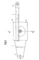
- - la Fig.1 est une vue de côté d'un dispositif selon l'invention ;
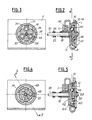
- - la Fig.2 est une vue en coupe suivant la ligne 2 - 2 de la Fig.1 montrant le dispositif en position de repos ;
- - la Fig.3 est une vue en coupe suivant la ligne 3 - 3 de la Fig.2 ;
- - la Fig.4 est une vue analogue à la Fig.3 du dispositif en position d'entraînement ; et
- - la Fig.5 est une vue en coupe suivant la ligne 5 - 5 de la Fig.4.
- Le dispositif, objet de l'invention est destiné à permettre le déplacement relatif de deux organes, c'est-à-dire généralement le déplacement d'un organe mobile par rapport à un organe fixe. Dans ce but, il comporte un flasque 1 fixé, en 3, sur l'un des organes, par exemple l'assise d'un siège de véhicule, et une barre 2 articulée en 4 sur l'autre organe, constitué, par exemple par le dossier inclinable du siège.
- Le flasque 1 est solidaire d'une plaque 6 recourbée en sens inverse à ses deux extrémités de sorte que sa partie inférieure 8 est fixée sur le flasque 1 tandis que sa partie supérieure forme un rail de guidage 10 qui pénètre dans une rainure longitudinale de la barre rectiligne 2.
- En regard, de cette plaque 6, le flasque 1 porte une couronne dentée 12 qui, dans la position de blocage représentée sur les Fig.2 et 3, est en prise avec une couronne dentée correspondante 14 solidaire d'une cuvette 16 libre en rotation dans une ouverture de la plaque 6. La cuvette 16 est solidaire d'un pignon 18 en prise avec la denture de la barre 2. Le pignon 18 est traversé axialement par une tige de commande 20 qui est supportée librement par le flasque 1 au centre de la couronne dentée 12. Un ressort hélicoïdal 22 entourant la tige 20 est monté entre une rondelle 24 solidaire de cette tige et l'extrémité du pignon 18 de sorte qu'il repousse constamment ce pignon, et par suite la cuvette 16, en direction de la denture 12 du flasque 1, c'est-à-dire vers la position d'immobilisation représentée sur la Fig.2.
- A l'intérieur de la cuvette 16, est monté un plateau d'entraînement 26 qui est percé en son centre d'un trou 28 de section carrée dans lequel est emboîté une portion 30 de section correspondante de la tige de commande 20, de sorte que ces deux organes sont solidaires en rotation.
- Le plateau 26 comporte sur sa périphérie un certain nombre de taquets 32, trois dans le mode réalisation représenté, qui sont logés chacun dans un évidement 34 de la cuvette 16. L'évidement 34 a une longueur circonférentielle nettement supérieure à celle du taquet 32 de sorte que ce dernier peut se déplacer sur une certaine distance avant d'entrer en contact avec le bord de la nervure 36 qui limite cet évidement.
- Le plateau 26 comporte en outre un certain nombre d'encoches dans lesquelles sont montées des billes. Ces encoches sont prévues dans ces deux grandes faces opposées, de sorte que sur sa face 38 en regard du flasque 1, font saillie des billes 40 qui sont simplement en appui sur le flasque. Tandis que, sur sa face 42, en regard du fond 44 de la cuvette 16 des billes 46 pénètrent dans des évidements sensiblement coniques 48 du fond 44 de la cuvette.
- Dans la position de repos représentée sur les Fig.2 et 3, les billes 46 sont ainsi solidement maintenues entre le plateau 26 et le fond de la cuvette 16 qui est repoussée par le ressort 22 contre le flasque 1. En outre, comme le montre la Fig.3, les taquets 32 se trouvent pratiquement au milieu des évidements 34 à égale distance des nervures 36.
- Lorsque la tige de commande 20 est entraînée en rotation, par exemple au moyen d'un bouton moleté (non représenté) et tourne par rapport au flasque 1 et à la denture 12, le plateau 26 tourne également en entraînant les billes 46 qui roulent vers l'extérieur des logements coniques 32 du fond 44 de la cuvette 16. Le plateau 26 passe alors progressivement de la position représentée sur la Fig.3 à celle représentée sur les Fig.4 et 5. Au cours de ce déplacement, les billes 46 en glissant sur les bords des évidements coniques 48 ont repoussé la cuvette 16 et par suite le manchon 18 axialement le long de la tige de commande 20, de sorte que la denture 14 s'est écartée de la denture 12 (Fig.5). Par ailleurs, chacun des taquets 32 est arrivé à l'extrémité de l'évidement 34 correspondant et est maintenant en contact avec une nervure 36. Si dans ces conditions, la tige de commande 20 continue à tourner, le plateau 26 par l'intermédiaire des taquets 32 et des nervures 36 entraîne la cuvette 16 et le pignon 18, ce qui provoque un déplacement longitudinal de la crémaillère 2 en prise avec ce pignon 18, et par suite un déplacement de l'organe articulé en 4 sur la barre 2.
- La rotation de la tige de commande 20 est poursuivie jusqu'au moment où le déplacement désiré a été obtenu. Dès que cette tige est relâchée les billes tendant à retomber d'elles mêmes au fond des évidements, le ressort 22 provoque un déplacement angulaire en sens inverse qui ramène les taquets 32 au centre de l'évidement 34 et remet ainsi immédiatement la cuvette 16 en prise avec la denture 12 du flasque 1, ce qui bloque l'ensemble du dispositif dans la position de réglage choisie. Les taquets 32 ayant été replacés au centre des évidements 34, la tige de commande 20 peut à nouveau être entraînée en rotation dans le sens dé siré, que ce soit le sens des aiguilles d'une montre ou le sens inverse, selon le déplacement que l'on a effectué et l'ensemble est totalement réversible.
- Il est clair qu'un tel dispositif peut être utilisé chaque fois que l'on désire obtenir le déplacement relatif de deux organes au moyen d'une commande disposée en un point intermédiaire et qu'il peut notamment permettre aussi bien le réglage de l'inclinaison ou de la position en hauteur de l'assise d'un siège que celle de l'inclinaison du dossier mentionnée ci-dessus.
- Dans certains cas, toutefois il peut être avantageux de remplacer les encoches du plateau 26 par des évidements tronconiques analogues à ceux du fond de la cuvette 16, de sorte que les billes glissent simultanément sur les bords inclinés des deux évidements en regard. Le déplacement de la cuvette, c'est-à-dire le déverrouillage, est ainsi accéléré. De même, les billes 40 peuvent être remplacées par des rondelles, des patins ou d'autres organes de frottement.
Claims (6)
Priority Applications (1)
| Application Number | Priority Date | Filing Date | Title |
|---|---|---|---|
| AT87400671T ATE54764T1 (de) | 1986-04-01 | 1987-03-25 | Antriebsvorrichtung zum relativen verstellen von zwei teilen, insbesondere fuer fahrzeugsitze. |
Applications Claiming Priority (2)
| Application Number | Priority Date | Filing Date | Title |
|---|---|---|---|
| FR8604614 | 1986-04-01 | ||
| FR8604614A FR2596541B1 (fr) | 1986-04-01 | 1986-04-01 | Dispositif de commande du deplacement relatif de deux organes, notamment pour siege de vehicule |
Publications (2)
| Publication Number | Publication Date |
|---|---|
| EP0240416A1 true EP0240416A1 (fr) | 1987-10-07 |
| EP0240416B1 EP0240416B1 (fr) | 1990-07-18 |
Family
ID=9333738
Family Applications (1)
| Application Number | Title | Priority Date | Filing Date |
|---|---|---|---|
| EP87400671A Expired - Lifetime EP0240416B1 (fr) | 1986-04-01 | 1987-03-25 | Dispositif de commande du déplacement relatif de deux organes, notamment pour siège de véhicule |
Country Status (9)
| Country | Link |
|---|---|
| US (1) | US4700587A (fr) |
| EP (1) | EP0240416B1 (fr) |
| JP (1) | JPS6323022A (fr) |
| KR (1) | KR870009682A (fr) |
| AT (1) | ATE54764T1 (fr) |
| CA (1) | CA1274463A (fr) |
| DE (1) | DE3763722D1 (fr) |
| ES (1) | ES2016370B3 (fr) |
| FR (1) | FR2596541B1 (fr) |
Cited By (2)
| Publication number | Priority date | Publication date | Assignee | Title |
|---|---|---|---|---|
| FR2652129A1 (fr) * | 1989-09-21 | 1991-03-22 | Cousin Freres Sa | Dispositif de blocage de verins mecaniques a deplacement soit rectiligne, soit circulaire. |
| FR2683273A1 (fr) * | 1991-11-06 | 1993-05-07 | Faure Bertrand Automobile | Verin de positionnement a cremaillere et a grains dentes. |
Families Citing this family (4)
| Publication number | Priority date | Publication date | Assignee | Title |
|---|---|---|---|---|
| US4840083A (en) * | 1988-03-14 | 1989-06-20 | Elco Industries, Inc. | Device for dampening rotary motion |
| DE4436221C1 (de) * | 1994-10-11 | 1996-02-22 | Keiper Recaro Gmbh Co | Verriegelungsvorrichtung für Fahrzeugsitze |
| DE19939115A1 (de) * | 1998-08-20 | 2000-02-24 | Ntn Toyo Bearing Co Ltd | Sitz mit verstellbarer Lehne für ein Fahrzeug |
| US7677666B2 (en) | 2008-01-09 | 2010-03-16 | Bae Industries, Inc. | Disc recliner assembly incorporated into a seatback/seat base pivot associated with a vehicle seat |
Citations (4)
| Publication number | Priority date | Publication date | Assignee | Title |
|---|---|---|---|---|
| GB1090770A (en) * | 1965-01-30 | 1967-11-15 | Levi Clews | Improvements in seat reclining mechanisms |
| US3411377A (en) * | 1967-03-03 | 1968-11-19 | Oak Electro Netics Corp | Index mechanism with means for adjusting the angular orientation thereof |
| GB1168790A (en) * | 1965-11-29 | 1969-10-29 | Plessey Co Ltd | Improvements relating to Seat Adjusting Arrangements |
| FR2186904A5 (fr) * | 1972-05-29 | 1974-01-11 | Keiper Recaro Gmbh Co |
Family Cites Families (4)
| Publication number | Priority date | Publication date | Assignee | Title |
|---|---|---|---|---|
| US2684741A (en) * | 1948-10-08 | 1954-07-27 | Bendix Aviat Corp | Coupling device |
| US3099485A (en) * | 1959-08-25 | 1963-07-30 | Stuttgarter Karosseriewerk Reu | Hinge unit for seat with adjustable back rest |
| DE1204542B (de) * | 1962-03-10 | 1965-11-04 | Recaro G M B H & Co | Gelenkbeschlag zum stufenlosen Verstellen der Lehnenneigung eines Sitzes, insbesondere eines Kraftfahrzeugsitzes |
| US3786693A (en) * | 1972-05-25 | 1974-01-22 | Teletype Corp | Detent mechanism for releasably securing relatively rotatable members |
-
1986
- 1986-04-01 FR FR8604614A patent/FR2596541B1/fr not_active Expired
- 1986-06-13 US US06/876,521 patent/US4700587A/en not_active Expired - Fee Related
-
1987
- 1987-03-25 EP EP87400671A patent/EP0240416B1/fr not_active Expired - Lifetime
- 1987-03-25 AT AT87400671T patent/ATE54764T1/de not_active IP Right Cessation
- 1987-03-25 ES ES87400671T patent/ES2016370B3/es not_active Expired - Lifetime
- 1987-03-25 DE DE8787400671T patent/DE3763722D1/de not_active Expired - Lifetime
- 1987-03-31 CA CA000533396A patent/CA1274463A/fr not_active Expired - Fee Related
- 1987-03-31 KR KR870003022A patent/KR870009682A/ko not_active Withdrawn
- 1987-04-01 JP JP62080849A patent/JPS6323022A/ja active Pending
Patent Citations (4)
| Publication number | Priority date | Publication date | Assignee | Title |
|---|---|---|---|---|
| GB1090770A (en) * | 1965-01-30 | 1967-11-15 | Levi Clews | Improvements in seat reclining mechanisms |
| GB1168790A (en) * | 1965-11-29 | 1969-10-29 | Plessey Co Ltd | Improvements relating to Seat Adjusting Arrangements |
| US3411377A (en) * | 1967-03-03 | 1968-11-19 | Oak Electro Netics Corp | Index mechanism with means for adjusting the angular orientation thereof |
| FR2186904A5 (fr) * | 1972-05-29 | 1974-01-11 | Keiper Recaro Gmbh Co |
Cited By (4)
| Publication number | Priority date | Publication date | Assignee | Title |
|---|---|---|---|---|
| FR2652129A1 (fr) * | 1989-09-21 | 1991-03-22 | Cousin Freres Sa | Dispositif de blocage de verins mecaniques a deplacement soit rectiligne, soit circulaire. |
| EP0419336A1 (fr) * | 1989-09-21 | 1991-03-27 | Ets. Cousin Freres | Dispositif de blocage de vérins mécaniques à déplacement soit rectiligne, soit circulaire |
| FR2683273A1 (fr) * | 1991-11-06 | 1993-05-07 | Faure Bertrand Automobile | Verin de positionnement a cremaillere et a grains dentes. |
| EP0541433A1 (fr) * | 1991-11-06 | 1993-05-12 | Bertrand Faure Automobile "B.F.A." | Vérin de positionnement à crémaillère et à grains dentés |
Also Published As
| Publication number | Publication date |
|---|---|
| FR2596541A1 (fr) | 1987-10-02 |
| FR2596541B1 (fr) | 1988-07-08 |
| DE3763722D1 (de) | 1990-08-23 |
| ES2016370B3 (es) | 1990-11-01 |
| JPS6323022A (ja) | 1988-01-30 |
| CA1274463A (fr) | 1990-09-25 |
| US4700587A (en) | 1987-10-20 |
| ATE54764T1 (de) | 1990-08-15 |
| KR870009682A (ko) | 1987-11-30 |
| EP0240416B1 (fr) | 1990-07-18 |
Similar Documents
| Publication | Publication Date | Title |
|---|---|---|
| EP0546896B1 (fr) | Base tournante à sécurité permettant la rotation de 180 degrés d'un siège dans un véhicule automobile ou analogue | |
| FR2750186A1 (fr) | Mecanisme de commande d'un organe rotatif au moyen d'une poignee pivotante, et siege equipe d'un tel mecanisme | |
| EP0427584A1 (fr) | Dispositif de maintien d'un organe tubulaire en particulier d'une colonne de direction de véhicule automobile | |
| FR2601571A1 (fr) | Ferrure d'articulation pour sieges, notamment des sieges de vehicule a dossier reglable. | |
| FR2562003A1 (fr) | Dispositif de reglage d'un coussin d'assise de siege, notamment dans un vehicule automobile | |
| FR2624239A1 (fr) | Mecanisme reducteur sans jeu utilisable notamment pour le reglage de diverses parties d'un siege de vehicule automobile | |
| EP0515275A1 (fr) | Plateau formant base tournante pour siège de véhicule | |
| EP0618089B1 (fr) | Roulette pivotante à blocage directionnel | |
| EP0348276B1 (fr) | Accoudoir central pivotant pour siège de véhicule automobile | |
| FR2463596A1 (fr) | Dispositif de reglage de l'inclinaison relative de deux organes et notamment des deux parties d'un siege de vehicule automobile | |
| FR2610806A1 (fr) | Articulation tournante pour sieges a dossier reglable | |
| FR2498536A1 (fr) | Dispositif de reglage de siege, notamment pour un siege de vehicule automobile | |
| EP0410850B1 (fr) | Dispositif permettant la compensation des jeux entre satellite et dentures des flasques de mécanismes réducteurs pour le réglage des positions des sièges, en particulier de sièges d'automobiles | |
| EP0340118B1 (fr) | Articulation continue irreversible | |
| FR2649942A1 (fr) | Ferrure d'articulation pour sieges, en particulier pour sieges de vehicules automobiles comportant un dossier reglable et susceptible de pivoter librement | |
| EP0240416B1 (fr) | Dispositif de commande du déplacement relatif de deux organes, notamment pour siège de véhicule | |
| FR2525365A1 (fr) | Dispositif de commande a manivelle pour toit ouvrant de vehicule automobile | |
| FR2471793A1 (fr) | Dispositif de blocage d'une extremite d'une ceinture de securite pour vehicules automobiles, combine avec une glissiere d'un siege | |
| EP0225228A1 (fr) | Dispositif de réglage de la position d'un renvoi de sangle de ceinture de sécurité | |
| FR2633566A1 (fr) | Accoudoir pour siege avant de vehicule | |
| FR2638689A1 (fr) | Mecanisme pour ceinture de securite a position reglable manuellement | |
| EP0443910A1 (fr) | Dispositif de blocage d'un organe tubulaire et en particulier d'une colonne de direction de véhicule automobile | |
| EP0018294B1 (fr) | Support pour un bras rabattable de rétroviseur extérieur | |
| EP0948303B1 (fr) | Dispositif de blocage | |
| EP0457699A2 (fr) | Dispositif d'accrochage automatique au plancher d'un véhicule d'un moyen de fixation d'une ceinture de sécurité |
Legal Events
| Date | Code | Title | Description |
|---|---|---|---|
| PUAI | Public reference made under article 153(3) epc to a published international application that has entered the european phase |
Free format text: ORIGINAL CODE: 0009012 |
|
| AK | Designated contracting states |
Kind code of ref document: A1 Designated state(s): AT BE CH DE ES GB IT LI LU NL SE |
|
| 17P | Request for examination filed |
Effective date: 19870923 |
|
| 17Q | First examination report despatched |
Effective date: 19881024 |
|
| RAP1 | Party data changed (applicant data changed or rights of an application transferred) |
Owner name: ECIA - EQUIPEMENTS ET COMPOSANTS POUR L'INDUSTRIE |
|
| GRAA | (expected) grant |
Free format text: ORIGINAL CODE: 0009210 |
|
| AK | Designated contracting states |
Kind code of ref document: B1 Designated state(s): AT BE CH DE ES GB IT LI LU NL SE |
|
| REF | Corresponds to: |
Ref document number: 54764 Country of ref document: AT Date of ref document: 19900815 Kind code of ref document: T |
|
| ITF | It: translation for a ep patent filed | ||
| GBT | Gb: translation of ep patent filed (gb section 77(6)(a)/1977) | ||
| REF | Corresponds to: |
Ref document number: 3763722 Country of ref document: DE Date of ref document: 19900823 |
|
| PGFP | Annual fee paid to national office [announced via postgrant information from national office to epo] |
Ref country code: CH Payment date: 19910221 Year of fee payment: 5 |
|
| PGFP | Annual fee paid to national office [announced via postgrant information from national office to epo] |
Ref country code: AT Payment date: 19910228 Year of fee payment: 5 |
|
| PGFP | Annual fee paid to national office [announced via postgrant information from national office to epo] |
Ref country code: LU Payment date: 19910322 Year of fee payment: 5 |
|
| PLBE | No opposition filed within time limit |
Free format text: ORIGINAL CODE: 0009261 |
|
| STAA | Information on the status of an ep patent application or granted ep patent |
Free format text: STATUS: NO OPPOSITION FILED WITHIN TIME LIMIT |
|
| 26N | No opposition filed | ||
| EPTA | Lu: last paid annual fee | ||
| PGFP | Annual fee paid to national office [announced via postgrant information from national office to epo] |
Ref country code: DE Payment date: 19920129 Year of fee payment: 6 |
|
| PGFP | Annual fee paid to national office [announced via postgrant information from national office to epo] |
Ref country code: GB Payment date: 19920317 Year of fee payment: 6 |
|
| PG25 | Lapsed in a contracting state [announced via postgrant information from national office to epo] |
Ref country code: LU Free format text: LAPSE BECAUSE OF NON-PAYMENT OF DUE FEES Effective date: 19920325 Ref country code: AT Effective date: 19920325 |
|
| PGFP | Annual fee paid to national office [announced via postgrant information from national office to epo] |
Ref country code: SE Payment date: 19920326 Year of fee payment: 6 |
|
| ITTA | It: last paid annual fee | ||
| PG25 | Lapsed in a contracting state [announced via postgrant information from national office to epo] |
Ref country code: LI Effective date: 19920331 Ref country code: CH Effective date: 19920331 |
|
| PGFP | Annual fee paid to national office [announced via postgrant information from national office to epo] |
Ref country code: NL Payment date: 19920331 Year of fee payment: 6 Ref country code: ES Payment date: 19920331 Year of fee payment: 6 |
|
| PGFP | Annual fee paid to national office [announced via postgrant information from national office to epo] |
Ref country code: BE Payment date: 19920409 Year of fee payment: 6 |
|
| REG | Reference to a national code |
Ref country code: GB Ref legal event code: 732 |
|
| REG | Reference to a national code |
Ref country code: CH Ref legal event code: PL |
|
| ITPR | It: changes in ownership of a european patent |
Owner name: CESSIONE;CESA - COMPAGNIE EUROPEENNE DE SIEGES POU |
|
| PG25 | Lapsed in a contracting state [announced via postgrant information from national office to epo] |
Ref country code: GB Effective date: 19930325 |
|
| PG25 | Lapsed in a contracting state [announced via postgrant information from national office to epo] |
Ref country code: SE Effective date: 19930326 Ref country code: ES Free format text: LAPSE BECAUSE OF NON-PAYMENT OF DUE FEES Effective date: 19930326 |
|
| PG25 | Lapsed in a contracting state [announced via postgrant information from national office to epo] |
Ref country code: BE Effective date: 19930331 |
|
| REG | Reference to a national code |
Ref country code: ES Ref legal event code: PC2A Owner name: CESA-COMPAGNIE EUROPEENNE DE SIEGES POUR AUTOMOBIL |
|
| BERE | Be: lapsed |
Owner name: CIE EUROPEENNE DE SIEGES POUR AUTOMOBILES CESA Effective date: 19930331 |
|
| PG25 | Lapsed in a contracting state [announced via postgrant information from national office to epo] |
Ref country code: NL Effective date: 19931001 |
|
| NLS | Nl: assignments of ep-patents |
Owner name: CESA-COMPAGNIE EUROPEENNE DE SIEGES POUR AUTOMOBIL |
|
| NLV4 | Nl: lapsed or anulled due to non-payment of the annual fee | ||
| GBPC | Gb: european patent ceased through non-payment of renewal fee |
Effective date: 19930325 |
|
| PG25 | Lapsed in a contracting state [announced via postgrant information from national office to epo] |
Ref country code: DE Effective date: 19931201 |
|
| EUG | Se: european patent has lapsed |
Ref document number: 87400671.1 Effective date: 19931008 |
|
| REG | Reference to a national code |
Ref country code: ES Ref legal event code: FD2A Effective date: 19990201 |
|
| PG25 | Lapsed in a contracting state [announced via postgrant information from national office to epo] |
Ref country code: IT Free format text: LAPSE BECAUSE OF NON-PAYMENT OF DUE FEES Effective date: 20050325 |