EP0240588A1 - Procédé et dispositif pour mélanger du ciment - Google Patents
Procédé et dispositif pour mélanger du ciment Download PDFInfo
- Publication number
- EP0240588A1 EP0240588A1 EP86104937A EP86104937A EP0240588A1 EP 0240588 A1 EP0240588 A1 EP 0240588A1 EP 86104937 A EP86104937 A EP 86104937A EP 86104937 A EP86104937 A EP 86104937A EP 0240588 A1 EP0240588 A1 EP 0240588A1
- Authority
- EP
- European Patent Office
- Prior art keywords
- water
- cement
- vessel
- batcher
- slurry
- Prior art date
- Legal status (The legal status is an assumption and is not a legal conclusion. Google has not performed a legal analysis and makes no representation as to the accuracy of the status listed.)
- Withdrawn
Links
- 239000004568 cement Substances 0.000 title claims abstract description 122
- 238000000034 method Methods 0.000 title claims abstract description 11
- 230000008569 process Effects 0.000 title claims abstract description 11
- XLYOFNOQVPJJNP-UHFFFAOYSA-N water Substances O XLYOFNOQVPJJNP-UHFFFAOYSA-N 0.000 claims abstract description 124
- 239000002002 slurry Substances 0.000 claims abstract description 54
- 239000000428 dust Substances 0.000 claims abstract description 41
- 238000013022 venting Methods 0.000 claims abstract description 5
- 239000004567 concrete Substances 0.000 claims description 15
- 230000001105 regulatory effect Effects 0.000 claims description 6
- 238000007599 discharging Methods 0.000 claims description 2
- 230000000063 preceeding effect Effects 0.000 claims 3
- 239000007788 liquid Substances 0.000 claims 1
- 239000012254 powdered material Substances 0.000 claims 1
- 239000000383 hazardous chemical Substances 0.000 abstract 2
- 239000003570 air Substances 0.000 description 33
- 238000011010 flushing procedure Methods 0.000 description 10
- 239000012080 ambient air Substances 0.000 description 6
- 239000012615 aggregate Substances 0.000 description 4
- 238000004519 manufacturing process Methods 0.000 description 3
- 238000005406 washing Methods 0.000 description 3
- 206010016825 Flushing Diseases 0.000 description 2
- 230000009471 action Effects 0.000 description 1
- 238000005266 casting Methods 0.000 description 1
- 238000010276 construction Methods 0.000 description 1
- 230000001276 controlling effect Effects 0.000 description 1
- 230000001186 cumulative effect Effects 0.000 description 1
- 230000002950 deficient Effects 0.000 description 1
- 238000006073 displacement reaction Methods 0.000 description 1
- 238000009826 distribution Methods 0.000 description 1
- 230000000694 effects Effects 0.000 description 1
- 230000007613 environmental effect Effects 0.000 description 1
- 239000003344 environmental pollutant Substances 0.000 description 1
- 230000005484 gravity Effects 0.000 description 1
- 231100000206 health hazard Toxicity 0.000 description 1
- 238000007689 inspection Methods 0.000 description 1
- 239000000203 mixture Substances 0.000 description 1
- 238000012544 monitoring process Methods 0.000 description 1
- 231100000719 pollutant Toxicity 0.000 description 1
- 230000009467 reduction Effects 0.000 description 1
- 238000009420 retrofitting Methods 0.000 description 1
- 239000004576 sand Substances 0.000 description 1
- 239000007921 spray Substances 0.000 description 1
- 239000002351 wastewater Substances 0.000 description 1
- 238000005303 weighing Methods 0.000 description 1
Images



Classifications
-
- B—PERFORMING OPERATIONS; TRANSPORTING
- B01—PHYSICAL OR CHEMICAL PROCESSES OR APPARATUS IN GENERAL
- B01F—MIXING, e.g. DISSOLVING, EMULSIFYING OR DISPERSING
- B01F35/00—Accessories for mixers; Auxiliary operations or auxiliary devices; Parts or details of general application
- B01F35/181—Preventing generation of dust or dirt; Sieves; Filters
Definitions
- This invention relates to a novel process and apparatus used in producing a cement slurry on a batch basis.
- cement slurry can be quickly and repeatedly mixed on a batch basis with no or little environmental cement dust being produced and in so doing, the process also allows concrete mixers, such as truck mounted concrete mixers, to be charged with the cement in slurry form without fear of additional dust pollution.
- the pre-measured quantities of cement and water added to the slurry mixer can be regulated or controlled prior to their introduction into the slurry mixer as contemplated, for example, by Manabe in United States Patent 2,015,488, in accordance with one preferred embodiment of my invention, it is possible to employ only one control means for regulating the amount of water and the amount of cement so introduced. In its simplest form, this is controlled and determined by regulating and thus determining the weight of the water added to the slurry mixer and similarly, weighing and determining the amount of cement added to the mixer thereby obviating the need of separate measuring devices for both the amount of water and amount of cement added.
- the cement slurry batcher be a substantially closed vessel into which the water and cement is added. Because the vessel is effectively closed, entrapped air contained therein must be exhausted at least during the addition of a pre-determined amount of cement since, on a volume basis significantly more cement than water is added to the vessel. As cement dust is carried by the vented air resulting from its displacement by the addition of cement, provision is made for air vent and cement dust collection means which communicates with the ambient air and which vents the otherwise entrapped air within the vessel.
- the air vent and cement dust collection means includes a water reservoir and conduit means for passing the entrapped air and cement dust through water contained in the reservoir.
- the water within the reservoir can itself, following the venting of the vessel, be added or discharged into the cement slurry.
- the cement dust contaminated reservoir water is itself taken up in the slurry and not disgarded as a pollutant.
- the waste water i.e. the water containing cement dust
- the amount of water in this reservoir or secondary chamber can advantageously be included in the predetermined amount of water that is added to the vessel during each batch operation.
- the novel cement slurry batcher of my invention used in mixing on a batch basis a pre-determined amount of cement with a pre-determined amount of water, comprises a substantially closed batching vessel for receiving said water and said cement.
- Cement inlet and water inlet means is provided in the batcher as is mixing means for mixing said water and said cement into a slurry.
- Slurry discharge means is provided on the bottom of the batching vessel.
- Control means is also employed for regulating the amount of water and the amount of cement introduced into the vessel during each batch and as above indicated, air vent and cement dust collection means communicating with the ambient air is employed for venting entrapped air and collecting cement dust carried thereby during at least the introduction of said cement into the vessel.
- the amount of added water and cement can be determined and measured externally of the vessel or controlled and regulated, on a weight basis, by determining the weight of the water in the vessel and the weight of the cement in the vessel.
- the air vent and cement dust collection means includes a water reservoir and conduit means for passing said entrapped air and cement dust through water contained in said reservoir.
- the water containing cement dust collected or otherwise filtered therethrough preferrably is discharged into the vessel following the addition of cement with the amount of water contained in the reservoir being calculated into the overall pre-determined amount of water added to the vessel during each batching operation.
- One simple form of air vent and cement dust collection means employing a water reservoir is the provision of conduit means which, at one end, communicates with the interior of the vessel and which, at the other end, ends below the surface of the water such that cement dust entrapped air vented from the vessel is obliged to bubble or otherwise pass through the water in the reservoir.
- the cement dust contaminated water can be gravity or pressure fed directly into the slurry mixer from the reservoir positioned above, or optionally, directed to introduce itself at selected locations within the mixer for the purpose of a more uniform introduction to the existing slurry.
- a first major quantity of a pre-determined amount of water is added to the substantially closed mixing vessel or batcher and a second minor quantity of said predetermined amount of water is added to a water reservoir or secondary reservoir.
- a pre-determined amount of cement is then added to the vessel and mixed with the first major quantity of water.
- the cement dust produced within the vessel during the addition of cement is vented as exhausted air through the second minor quantity of water. Thereafter, this second minor quantity of air which has picked up the cement dust exhausted from the vessel, is added to the first major quantity of water and the cement which is undergoing slurry mixing.
- the pre-determined amounts of water and cement used during each batch can be determined externally of the slurry mixing vessel prior to addition or, and as is preferred, simply determined and controlled by measuring or monitoring the weight of the water and the weight of cement added to the vessel.
- both the apparatus and the process of it can be carried out merely by retrofitting many existing concrete plants.
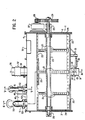
- the slurry batcher is generally indicated by reference numeral I and includes end wall portions 2 and 3 and a central mixing drum or cylinder 4.
- Batcher 1 is supported by a centrally located drum support leg 5 on one side and two spaced apart drum legs 6 on the opposite side and carried by support or base brackets with load cells which are generally located and generally indicated at 7 and as discussed in greater detail below.
- Load cells 7 themselves are carried by a supporting framework (not shown) as is well known in the art.
- Discharge pipe 9 for discharging the slurry mixed within batcher 1 is located on the underside of the drum 4. Included on pipe 9 is closure or butterfly valve 10 adapted to sealingly engaged closure gasket 11. One end of a shaft 12 of valve 10 is connected to crank arm 13 with the valve being opened and closed by solonoid actuated air cylinder 14 carried on support bracket 15 in a well known manner.
- the batcher itself may be elevated on supports (not shown) in order to permit a concrete truck to drive thereunder and receive the cement slurry discharged through pipe 9.
- the mixing means located internally of batcher 1 may be of any suitable form of construction but as illustrated, employs an elongate shaft 23 central of mixing drum 4 and supported at end walls 2 and 3 by shaft end bearings generally indicated at 25.
- Radial arms 21 extend radially outward from and are fixed to rotatable central shaft 23.
- the free ends of the radial arms are connected to elongate cross supports 22 which in turn include wiper blades 20 as best seen in Figure 3 and which are intended to wipe the interior wall of mixing drum 4 while rotated in the direction of arrow 30.
- End supports 24 connect cross supports 22.
- electric drive motor 26, reduction gearbox 27 with drive pinion 28 are supported on end wall 2.
- Driven gear 23 is also carried externally of wall 2 and is fixedly connected to shaft 23 in order to rotate the slurry mixing means as above described.
- a cover plate 31 for this drive means can be mounted over the motor, gearbox and driven gear as illustrated in Figure 4.
- a shut off valve for discharge tube 36 (not shown) is provided and functions in a manner similar to slurry valve 10 for controlling the amount of cement permitted to enter drum 4. Also provided on the top of this drum is removable inspection and service cover or port 39.
- Water is introduced into the batcher through pipe 51 connected to supply pipe 50 which also communicates with secondary water supply pipe 52 as best illustrated in Figure 3 and which terminates interiorally of secondary water drum or reservoir 45 attached to mixing drum 4 by mounting brackets or straps generally indicated at 46.
- Inlet pipe 51 additionally includes a main water shut off valve 53 which, as before, is connected to actuation lever arm 54 and air driven solonoid valve or piston 55 so as to control the entry of water internally of the batcher.
- secondary drum inlet pipe 52 includes a further shut off valve 58 controlled by lever arm 59 actuated by air piston 60.
- secondary water drum 45 also includes a breather shut off valve generally indicated at 67 and which, when opened permits the interior of drum 45 to communicate with the ambient air.
- Valve 67 together with solonoid actuated valve 65 are both positioned above water level 64 of the water in drum 45 as discussed in greater detail below.
- Solonoid valve 65 controls the entry of compressed air into drum 45 supplied by compressed air supply hose 66.
- air vent pipe 61 communicates with the interior of batcher 1 and the interior of drum 45 so as to extend below water level 64.
- a lever and valve arrangement generally indicated at 62 serves to shut off the air vent upon actuation of air piston 63.
- a further solonoid actuated control valve 70 is positioned approximate the bottom of secondary water drum 45 which, when opened, permits the water in this drum to flow via pipe 71 to a flushing manifold or distributor 72 as illustrated in Figure 4. Also connected to flushing manifold 72 are a series of distribution pipes 73 which, at their ends remote from the manifold, terminate and communicate with the interior of the batcher at flushing nozzles 74 which serves to spray water into batcher. As illustrated, two flushing nozzles are located on the top of the batcher and two flushing nozzles 74 are provided on the end walls 2 and 3 of the batcher. As described in greater detail hereinbelow, the content of water in secondary water tank 45 is drained off and introduced internally of drum 1 to assist in washing the interior walls of the drum.
- valve 10 is closed as is the valve on the cement hopper supply (not shown). Valves 53 and 58 on the water supply pipes 51 and 52 are also closed as is valve 70 and compressed air valve 65 while breather shut off valve 67 communicating with the ambient air is opened. The weight of the overall batcher is then determined employing load cells 7 in a manner as is well known in the art.
- valves 58 and 53 are then opened permitting the entry of water into batcher 1 and resevoir 45.
- valve 58 is automatically closed whereupon water is permitted to continually add to drum 4.
- valve 53 is closed in a known manner; the weight of water and the batcher being determined by the weight upon load cell 7.
- the mixing means internally of the batcher can be started up prior to or during the water addition as desired.
- the level of both the water and cement being shown as 8 in Figure 3.
- air vent valve 62 is opened as is the valve on the hopper (not shown) to permit cement to enter the batcher.
- the hopper valve is caused to automatically shut off in a known manner when the weight of the batcher, the weight of the water and the weight of the cement added there to meets a pre-set value representing the desired ratio of cement to be added to the water.
- the cement is mixed with the water within the batcher and the attendent dust is carried off by the displaced air within the batcher as it is permitted to exhaust itself by passage through air vent 61 the water in drum 45 and finally through breather shut off valve 67 which is in the open position to the ambient air; the dust carried by this expelled air being effectively filtered out by being bubbled through and absorbed by the water in drum 45.
- this is achieved by the closure of air vent valve 62 and breather shut off valve 65 and the opening of flushing valve 70 which thereby permits the water in the 45 tank to follow through valve 70 and pipe 71 to manifold 72 and thence via distributor pipes 73 to flush this water carrying the accumulated cement dust through flushing nozzles 74 for discharge into the batcher.
- the pressure head on this flushed water and the flushing action of the water discharged through nozzle 74 is significantly improved by utilizing air pressure supply hose 66 and opening valve 65 communicating with the interior of drum 45.
- the water deficient slurry can be expelled via valve 10 prior to flushing the batcher with the water of drum 45.
- the water depleted slurry can be first introduced into the concrete truck and the balance of the water, following flushing, then also introduced into the truck by merely leaving valve 10 open until the next batching operation. In this application, final slurry mixing would take place in the mixing truck.
- the cement dust is contained during a slurry mixer charging and furthermore, only one weight controller for measuring both the desired amount of cement and the desired amount of water is needed.
- Aggregate can be then mixed with the obtained slurry in any desired manner, such as, for example, adding the aggregate to the concrete mixer of a truck following the slurry addition.
Landscapes
- Chemical & Material Sciences (AREA)
- Chemical Kinetics & Catalysis (AREA)
- Preparation Of Clay, And Manufacture Of Mixtures Containing Clay Or Cement (AREA)
Priority Applications (2)
| Application Number | Priority Date | Filing Date | Title |
|---|---|---|---|
| US06/655,935 US4588299A (en) | 1983-10-18 | 1984-09-28 | Cement mixing process and apparatus |
| EP86104937A EP0240588A1 (fr) | 1986-04-10 | 1986-04-10 | Procédé et dispositif pour mélanger du ciment |
Applications Claiming Priority (1)
| Application Number | Priority Date | Filing Date | Title |
|---|---|---|---|
| EP86104937A EP0240588A1 (fr) | 1986-04-10 | 1986-04-10 | Procédé et dispositif pour mélanger du ciment |
Publications (1)
| Publication Number | Publication Date |
|---|---|
| EP0240588A1 true EP0240588A1 (fr) | 1987-10-14 |
Family
ID=8195052
Family Applications (1)
| Application Number | Title | Priority Date | Filing Date |
|---|---|---|---|
| EP86104937A Withdrawn EP0240588A1 (fr) | 1983-10-18 | 1986-04-10 | Procédé et dispositif pour mélanger du ciment |
Country Status (1)
| Country | Link |
|---|---|
| EP (1) | EP0240588A1 (fr) |
Cited By (3)
| Publication number | Priority date | Publication date | Assignee | Title |
|---|---|---|---|---|
| CN109570457A (zh) * | 2019-01-23 | 2019-04-05 | 山西大通铸业有限公司 | 一种具有除尘功能的自动加硅铁设备 |
| CN113829500A (zh) * | 2021-10-16 | 2021-12-24 | 孟范茹 | 一种混凝土及其加工方法 |
| CN113893782A (zh) * | 2021-10-22 | 2022-01-07 | 会同县凯润建材有限公司 | 一种水泥制造的硫中和处理设备 |
Citations (6)
| Publication number | Priority date | Publication date | Assignee | Title |
|---|---|---|---|---|
| CH341107A (de) * | 1956-07-23 | 1959-09-15 | Egli & Erbes | Gewichtsdosierungseinrichtung für Zement |
| FR1232826A (fr) * | 1958-08-18 | 1960-10-12 | Arbau Baugerate G M B H | Machine mélangeuse |
| US2970820A (en) * | 1959-03-05 | 1961-02-07 | Sepich Edward | Construction material mixer with batch gauge |
| US3325151A (en) * | 1964-01-31 | 1967-06-13 | Portasil Ltd | Concrete mixing and batching plant |
| DE2236543A1 (de) * | 1972-07-26 | 1974-02-07 | Stetter Gmbh | Verfahren und vorrichtung zum beschicken eines transportbetonmischers |
| DE2709220A1 (de) * | 1977-03-03 | 1978-09-07 | Elba Werk Maschinen Gmbh & Co | Entstaubungsvorrichtung fuer mischer, insbesondere betonmischer |
-
1986
- 1986-04-10 EP EP86104937A patent/EP0240588A1/fr not_active Withdrawn
Patent Citations (6)
| Publication number | Priority date | Publication date | Assignee | Title |
|---|---|---|---|---|
| CH341107A (de) * | 1956-07-23 | 1959-09-15 | Egli & Erbes | Gewichtsdosierungseinrichtung für Zement |
| FR1232826A (fr) * | 1958-08-18 | 1960-10-12 | Arbau Baugerate G M B H | Machine mélangeuse |
| US2970820A (en) * | 1959-03-05 | 1961-02-07 | Sepich Edward | Construction material mixer with batch gauge |
| US3325151A (en) * | 1964-01-31 | 1967-06-13 | Portasil Ltd | Concrete mixing and batching plant |
| DE2236543A1 (de) * | 1972-07-26 | 1974-02-07 | Stetter Gmbh | Verfahren und vorrichtung zum beschicken eines transportbetonmischers |
| DE2709220A1 (de) * | 1977-03-03 | 1978-09-07 | Elba Werk Maschinen Gmbh & Co | Entstaubungsvorrichtung fuer mischer, insbesondere betonmischer |
Cited By (4)
| Publication number | Priority date | Publication date | Assignee | Title |
|---|---|---|---|---|
| CN109570457A (zh) * | 2019-01-23 | 2019-04-05 | 山西大通铸业有限公司 | 一种具有除尘功能的自动加硅铁设备 |
| CN113829500A (zh) * | 2021-10-16 | 2021-12-24 | 孟范茹 | 一种混凝土及其加工方法 |
| CN113893782A (zh) * | 2021-10-22 | 2022-01-07 | 会同县凯润建材有限公司 | 一种水泥制造的硫中和处理设备 |
| CN113893782B (zh) * | 2021-10-22 | 2024-04-02 | 会同县凯润建材有限公司 | 一种水泥制造的硫中和处理设备 |
Similar Documents
| Publication | Publication Date | Title |
|---|---|---|
| US4588299A (en) | Cement mixing process and apparatus | |
| US5908240A (en) | Apparatus for cement blending capable of forming a thick slurry | |
| US4456176A (en) | Apparatus for processing and dispensing fertilizer or insecticide | |
| EP0017504B1 (fr) | Dispositif et procédé de récupération des boues résiduelles de béton | |
| US4390282A (en) | Container | |
| MXPA02009884A (es) | Planta de concreto portatil. | |
| US3905586A (en) | Mini-plant for batching and mixing materials | |
| CN110327838A (zh) | 一种可调节植物生长速率的试剂制备装置 | |
| CA1300593C (fr) | Procede et appareil de dosage de coulis de ciment | |
| EP0240588A1 (fr) | Procédé et dispositif pour mélanger du ciment | |
| GB2084036A (en) | Mixing apparatus for the discontinuous production of plastics foam bodies | |
| JPS58222257A (ja) | モルタルの調製方法及び装置 | |
| EP0482720A1 (fr) | Procédé et dispositif pour proportioner, mélanger et appliquer un mortier spécifique | |
| CA1214457A (fr) | Methode et dispositif de preparation de ciment hydraulique | |
| US2031326A (en) | Mortar mixer | |
| US3812889A (en) | Dust control system utilizing temporarily stored aggregates | |
| GB2095569A (en) | Plant for mixing the constituents of a settable building material composition | |
| DE3504397C2 (fr) | ||
| CN220075076U (zh) | 一种方便上料的砂浆搅拌装置 | |
| RU23175U1 (ru) | Смесительная установка | |
| CN215506457U (zh) | 一种液体农药配比器 | |
| CN214416158U (zh) | 一种用于市政园林维护的农药混药装置 | |
| JPS62257812A (ja) | スラリバツチヤ及びスラリの製造方法 | |
| JP4144747B2 (ja) | 骨材及び水の計量装置並びにそれを用いたセメント系流動固化材の吹付けシステム | |
| JP3221616U (ja) | バッチャープラントのフィルタ構造 |
Legal Events
| Date | Code | Title | Description |
|---|---|---|---|
| PUAI | Public reference made under article 153(3) epc to a published international application that has entered the european phase |
Free format text: ORIGINAL CODE: 0009012 |
|
| AK | Designated contracting states |
Kind code of ref document: A1 Designated state(s): AT BE CH DE FR GB IT LI SE |
|
| STAA | Information on the status of an ep patent application or granted ep patent |
Free format text: STATUS: THE APPLICATION IS DEEMED TO BE WITHDRAWN |
|
| 18D | Application deemed to be withdrawn |
Effective date: 19880415 |
|
| RIN1 | Information on inventor provided before grant (corrected) |
Inventor name: DELORME, ERNEST J. Inventor name: BROWN, RONALD O. |