EP0240594B1 - Dispositif pour la distribution de béton dans les ouvrages souterrains - Google Patents
Dispositif pour la distribution de béton dans les ouvrages souterrains Download PDFInfo
- Publication number
- EP0240594B1 EP0240594B1 EP86111687A EP86111687A EP0240594B1 EP 0240594 B1 EP0240594 B1 EP 0240594B1 EP 86111687 A EP86111687 A EP 86111687A EP 86111687 A EP86111687 A EP 86111687A EP 0240594 B1 EP0240594 B1 EP 0240594B1
- Authority
- EP
- European Patent Office
- Prior art keywords
- drum
- mixing
- tubular drum
- concrete
- tubular
- Prior art date
- Legal status (The legal status is an assumption and is not a legal conclusion. Google has not performed a legal analysis and makes no representation as to the accuracy of the status listed.)
- Expired - Lifetime
Links
Images

Classifications
-
- E—FIXED CONSTRUCTIONS
- E21—EARTH OR ROCK DRILLING; MINING
- E21D—SHAFTS; TUNNELS; GALLERIES; LARGE UNDERGROUND CHAMBERS
- E21D11/00—Lining tunnels, galleries or other underground cavities, e.g. large underground chambers; Linings therefor; Making such linings in situ, e.g. by assembling
- E21D11/04—Lining with building materials
- E21D11/10—Lining with building materials with concrete cast in situ; Shuttering also lost shutterings, e.g. made of blocks, of metal plates or other equipment adapted therefor
- E21D11/105—Transport or application of concrete specially adapted for the lining of tunnels or galleries ; Backfilling the space between main building element and the surrounding rock, e.g. with concrete
-
- B—PERFORMING OPERATIONS; TRANSPORTING
- B28—WORKING CEMENT, CLAY, OR STONE
- B28C—PREPARING CLAY; PRODUCING MIXTURES CONTAINING CLAY OR CEMENTITIOUS MATERIAL, e.g. PLASTER
- B28C5/00—Apparatus or methods for producing mixtures of cement with other substances, e.g. slurries, mortars, porous or fibrous compositions
- B28C5/42—Apparatus specially adapted for being mounted on vehicles with provision for mixing during transport
- B28C5/4272—Apparatus specially adapted for being mounted on vehicles with provision for mixing during transport with rotating drum rotating about a horizontal or inclined axis, e.g. comprising tilting or raising means for the drum
- B28C5/4275—Apparatus specially adapted for being mounted on vehicles with provision for mixing during transport with rotating drum rotating about a horizontal or inclined axis, e.g. comprising tilting or raising means for the drum with a drum rotating about a horizontal axis, e.g. perpendicular to the longitudinal axis of the vehicle
Definitions
- the invention relates to a device for providing batches of concrete in underground operation according to the preamble of claim 1.
- the invention enables the provision of batches of concrete mainly in tunnel construction, but possibly also when expanding lines in mining. It relates to a device with which batches of concrete are only produced on site and not above ground and in which therefore cement on the one hand and dry or moist additives, if necessary with appropriate concrete additives, are transported separately but together on site. This means that there is no need to transport wet or earth-moist, ready-mixed concrete manufactured above ground and the associated subsequent mixing of the delivered concrete on site.
- the device according to the invention makes it possible, in particular, to prepare the concrete only when it is removed on site from the finishing work to be carried out there.
- So z. B a track-bound vehicle with a special structure, which has several containers in which cement and aggregates may be separated with additives, but transported together. Two containers arranged next to each other are intended for the cement of one batch of concrete: two additional containers contain the surcharges for each of these batches of concrete.
- the vehicle has an automatic clutch and a discharge conveyor. With the coupling, it can be connected to an on-site feed conveyor belt of a mobile mixer with a concrete pump arranged at the bottom, which takes over a batch of concrete from two containers and feeds the batch of concrete to the concrete pump. The loads belonging to a concrete batch are continuously removed with the vehicle's discharge conveyor belt.
- the container arrangement ensures that the cement is applied to the aggregate lying on the bottom of the concrete conveyor belt in a layer arranged at the top.
- the mixing takes place to a significant extent only in the mixer downstream of the feed belt. Water must be added to avoid dust formation. For this reason, the dry constituents of the concrete are first kept separate from each other and practically only mixed in the mixer with the addition of water, i.e. mixed.
- the disadvantage here is the comparatively poor quality of the concrete. On the one hand, this is a consequence of the irregularities in the bringing together of cement, aggregates and water caused by the described processes, which are primarily due to the uncontrollable run-out processes on the containers above the discharge belt, but also when adding water and are no longer in front of the concrete pump have it completely removed.
- a concrete mixing system is known from US Pat. No. 2,703,703, which consists of a road-going vehicle with a mixing drum arranged thereon.
- the components forming the concrete such as cement and aggregates are premixed dry in the drum and finished on site in a second drum arranged on the vehicle to produce the finished concrete with the addition of water.
- This device is therefore suitable for supplying several small customers, but not for concrete work in tunnel construction or even in underground mining.
- the invention is therefore based on the object to design the device known from US Pat. No. 1,894,129 such that the cement load as a whole is only poured onto the aggregate load after the concrete components have been transported, so that fresh quality concrete can be made available on site .
- all the irregularities in bringing together the dry components belonging to a batch of concrete are eliminated by the filling of the cement load onto the aggregate load after transport, ie on site.
- the total amount is homogenized as a result of its mixing, only then is it transported and mixed with the mixing water.
- This thorough mixing of the components not only leads to a completely uniform mixture and thus to a quality concrete.
- the train arrangement also has the advantage that the batch of concrete can be temporarily stored with further mixing, so that an even better coordination of the partial quantities of a batch of concrete with the purchase quantities can be achieved on site.
- the advantage of quality concrete is not lost.
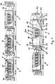
- the device according to the invention shown in FIG. 1 consists of several, coupled rail vehicles 1 to 5.
- the rail vehicles 1 and 2 are of identical design. The number of these identical vehicles can be increased beyond the number shown.
- the rail vehicles 3 and 4 have a modified structure compared to the rail vehicles 1 and 2. Their number can also be increased. However, it is sufficient if one of these vehicles is provided.
- the rail vehicle 5 has a structure of a special type. As a rule, only one of these vehicles is required on the train. It should also be noted that the rail vehicles have automatic clutches.
- type 3 or 4 and 5 rail vehicles are installed stationary for several work processes on site.
- Type 1 and 2 rail vehicles are coupled and uncoupled as required. These vehicles operate between above ground and underground. This mode of operation is intended for tunnel construction. If it is used in mining, the rail vehicles of type 1, 2 can also remain underground, provided that a corresponding filling device is available underground.
- the rail vehicles of type 1, 2 are a four-axle underframe 6 with a vehicle body 7 with a lying tubular drum 8. This contains a mixing and transport spiral 10 attached to the inner wall 9. Spacers 11 are made of sheet metal existing, further transport spiral 12 arranged concentrically to the outer spiral 10. The slopes are in opposite directions, so that the mixed material located in the tubular drum 8 is transported back and forth. The space 13 provided between the two spirals 10, 12 enables free-fall mixing.
- a cement silo 14 is left out of the interior of the tubular drum 8.
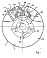
- This cement silo has the shape of a cylinder jacket segment. It is accordingly limited by the sheet metal skin 17 of the tubular drum 8 provided with manholes 15, 16. Inside, a parallel curved bottom 18 serves as an inner closure. Flat side walls 19, 20 complete the wall of the cement silo 14.
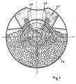
- the silo 14 has a floor drain, which is generally designated 21 in Figure 2.
- the floor emptying leads from the room of the cement silo 14 into the mixing room 23, which at the same time serves as a container for holding the dry aggregates or aggregates 23 of a batch of concrete.
- the bottom is emptied by two swivel flaps, which are shown in broken lines in the open state at 24 and 25 in FIG. 2.
- the flaps are adjusted using a handlebar linkage.
- a two-armed rocker arm 26 is connected, which is connected at one end to a hydraulic working cylinder 27 and pivots about a fixed axis 26a.
- Handlebars 27, 28 connect the rocker 26 to rockers 29 and 30, which pivot about fixed axes 31, 32 and thereby move and hold the flaps in the closed or in the open position via brackets on the outer skin of the swivel flaps 24, 25.
- the tubular drum 8 has a cylindrical section 34 and a cone 35 or 36 at each end.
- the tubular drum can be rotated about its central axis 39 via a drive 37 with a ring gear 38 arranged on the cylindrical section 34.
- the discharge end 33 is seated on the front cone 35, which has an axially movable closure cap 39 shown in dashed lines in FIG.
- the cover lies in the rear, shortened cone 36 of the preceding rail vehicle 2 of the same type.
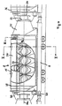
- the types 3 and 4 rail vehicles in turn have a four-axle chassis 40.
- the chassis has a structure 41 which is essentially formed by a tubular drum 42.
- the tubular drum has external dimensions that correspond to the structure of the type 1 and 2 rail vehicle. Accordingly, a cylindrical middle section 43 is provided with conical end sections 44, 45, of which the front cone has a discharge opening 46 which is provided with a closure cap 47.
- the cone 45 leads into the cone 44 of the preceding rail vehicle of the other type.
- a drive 48 rotates the mixing drum 42 via a ring gear 49. Inside the mixing drum is provided with a mixing spiral 10 or 12 of the same type as is used in the type 1 and 2 rail vehicles.
- the front rail vehicle 5 has - according to the exemplary embodiment - an elongated rail chassis 51.
- the structure consists of a tilting frame 52, the tilting axis 53 of which is arranged at the rear end of the rail vehicle 5.
- a tubular drum 54 is constructed on the tilting frame, which has a rear cone 47 and has a discharge opening 55 at the front end, which is provided with a closure cover 56. Because of the greater length of the cylindrical section 57, in contrast to the other tubular drums, the tubular drum 54 has three manholes 58 to 60 which can be closed with lids instead of the manholes 49 and 50 when the vehicles of type 3 and 4 or the manholes 15 and 16 of the type are built 1 and 2.
- the tubular drum 54 is also provided on the inside with the mixing spirals 10 and 12, which have been discussed in connection with FIGS. 2 and 3.
- the mixing drum 54 can also be rotated via a drive 61 and the ring gear 62.
- a tilt cylinder 62a is articulated in the chassis at 63 and on the underside of the tilt frame 52 at 64.
- the type 4 vehicle has a connection for mixing water which flows in from a line 66 via a quantity indicator 65. It reaches a distributor 67, from which a plurality of nozzles 68 and 69 are acted on, which are fastened to the inner spiral 12. This differs from Type 3, which also works as a mixer, but works dry.
- a plurality of type 1 and 2 rail vehicles are preferably filled through the open manholes 15, 16 with an additional load for a batch of concrete, the flaps being open.
- the flaps of the silo 14 After the flaps of the silo 14 have been closed, the amount of cement required for the batch of concrete in question is filled into the silo. It goes without saying that the quantities filled in are weighed as required for quality concrete. Then the manholes are closed.
- the type 1, 2 vehicles are then used to transport the separate loads for one or more batches of concrete on site. The transport route is ended as soon as the automatic coupling of the first train from vehicles 1, 2 has been connected to the automatic coupling of vehicle 3 of the second train.
- the flaps 24, 25 in the rail vehicle 2 traveling ahead are opened, so that the entire amount of cement is poured into the aggregate load at once when the tubular drum is rotating. This is indicated schematically in FIG. 2.
- the closure cover 39 is closed, intensive intensive thorough mixing of the loads described already takes place in the rail vehicle 2. If the relevant batch of concrete is called up, the lid 39 is opened or is already in the open state. Then the mixture easily enters the tubular drum of the rail vehicle 3. The construction of this vehicle is only used to complete the dry mix.
- the transport effect of the external worm 10 means that the mixture can overcome the distance between the rail vehicle 2 and the rail vehicle 4. This presupposes that the closure cover 47 is open. If the cover 47 is closed, the material to be mixed is circulated and further mixed dry.
- the mixed material enters the tubular drum of the rail vehicle 4.
- the rail vehicle 4 differs from the rail vehicle 3 only in the water supply 66, which has been described above. This enables an exact determination of the water-cement factor in the finished concrete. Since the water is supplied via the nozzles 68 and 69, the mixing water is evenly distributed in the dry mixture. At the same time, a lubricating film is formed on the flights of the screws 10, 12, which ensures the transport effect. If the cover 47 of the rail vehicle 4 is closed, the now wet concrete is thoroughly mixed in the tubular drum. As soon as the lid is opened, the finished batch of concrete arrives in the tubular drum 54 of the rail vehicle 5.
- the batch of concrete may be temporarily stored with the remainder of the previous batch of concrete still present.
- the tilting frame 52 enables the height of the discharge opening 55 to be adjusted, which is shown by the broken line in FIG. 1. This allows different feed heights for concrete pumps, conveyor belts, formwork openings or the like. to adjust.
- the tubular drum of the rail vehicle 2 runs along and serves as a means of transport for conveying the dry mixture into the subsequent rail vehicles of type 1 and 2, the automatic coupling of which is released with the rail vehicle 3.
- the train will be returned to reload.
- the facility enables an alternating train system and thus the provision of large quantities of quality concrete.
Landscapes
- Engineering & Computer Science (AREA)
- Structural Engineering (AREA)
- Architecture (AREA)
- Mining & Mineral Resources (AREA)
- Mechanical Engineering (AREA)
- Civil Engineering (AREA)
- Life Sciences & Earth Sciences (AREA)
- General Life Sciences & Earth Sciences (AREA)
- Geochemistry & Mineralogy (AREA)
- Geology (AREA)
- Preparation Of Clay, And Manufacture Of Mixtures Containing Clay Or Cement (AREA)
- On-Site Construction Work That Accompanies The Preparation And Application Of Concrete (AREA)
Claims (7)
Priority Applications (1)
| Application Number | Priority Date | Filing Date | Title |
|---|---|---|---|
| AT86111687T ATE55720T1 (de) | 1986-04-04 | 1986-08-23 | Vorrichtung zur bereitstellung von betonchargen im untertagebetrieb. |
Applications Claiming Priority (2)
| Application Number | Priority Date | Filing Date | Title |
|---|---|---|---|
| DE3611382 | 1986-04-04 | ||
| DE19863611382 DE3611382A1 (de) | 1986-04-04 | 1986-04-04 | Verfahren und vorrichtung zur bereitstellung von betonchargen im untertagebetrieb |
Publications (2)
| Publication Number | Publication Date |
|---|---|
| EP0240594A1 EP0240594A1 (fr) | 1987-10-14 |
| EP0240594B1 true EP0240594B1 (fr) | 1990-08-22 |
Family
ID=6297970
Family Applications (1)
| Application Number | Title | Priority Date | Filing Date |
|---|---|---|---|
| EP86111687A Expired - Lifetime EP0240594B1 (fr) | 1986-04-04 | 1986-08-23 | Dispositif pour la distribution de béton dans les ouvrages souterrains |
Country Status (3)
| Country | Link |
|---|---|
| EP (1) | EP0240594B1 (fr) |
| AT (1) | ATE55720T1 (fr) |
| DE (2) | DE3611382A1 (fr) |
Cited By (1)
| Publication number | Priority date | Publication date | Assignee | Title |
|---|---|---|---|---|
| CN103075185A (zh) * | 2013-01-31 | 2013-05-01 | 陈为朋 | 矿用喷射混凝土管式转载机 |
Families Citing this family (9)
| Publication number | Priority date | Publication date | Assignee | Title |
|---|---|---|---|---|
| CA2044602A1 (fr) * | 1989-01-16 | 1990-07-17 | Risto Minkkinen | Construction d'un reservoir sur un systeme de transport de vracs forme d'un camion et d'une semi-remorque |
| FI890687L (fi) * | 1989-02-14 | 1990-08-15 | Minkkinen Risto J | Betongpumpningssystem. |
| FI901974A7 (fi) * | 1990-04-20 | 1991-10-21 | Minkkinen Risto J | Massanlevitysjärjestelmä |
| DE4244282C2 (de) * | 1992-12-28 | 1997-04-17 | Riker Rudolf | Anlage zur Betonherstellung |
| ES2109729T3 (es) * | 1993-09-29 | 1998-01-16 | Imk Ingenieurkontor Fur Maschi | Transportador-mezclador para mezclas liquidas a granel. |
| AT409529B (de) * | 1998-05-25 | 2002-09-25 | Gapp Bernd | Verfahren und einrichtung zur verfestigung der oberfläche von gesteinshaltigem erdreich |
| ES2176048B1 (es) * | 1998-12-15 | 2004-02-01 | Ferroberica S L | Instalacion movil para la fabricacion de armaduras metalicas. |
| ATE552089T1 (de) * | 2006-09-08 | 2012-04-15 | Rowa Tunnelling Logistics Ag | Verfahren und vorrichtung zum betontransport auf schienen |
| CN113513340B (zh) * | 2021-03-17 | 2024-08-02 | 山东能源集团鲁西矿业有限公司 | 一种煤矿井下用超远距离喷浆系统及使用方法 |
Family Cites Families (5)
| Publication number | Priority date | Publication date | Assignee | Title |
|---|---|---|---|---|
| US1894129A (en) * | 1928-05-14 | 1933-01-10 | Harry J Shaw | Concrete delivery |
| DE815162C (de) * | 1949-02-22 | 1951-11-29 | Emil Schleif | Transportvorrichtung fuer trockenes Gut, insbesondere gemischte Baustoffe |
| US2703703A (en) * | 1953-04-30 | 1955-03-08 | Nargelovic John | Concrete mixing system |
| US3282448A (en) * | 1964-07-22 | 1966-11-01 | Robert A Mcneil | Method and apparatus for conveying construction material |
| US3567190A (en) * | 1968-12-12 | 1971-03-02 | Ray D Moran | Drum car and coupling apparatus for carrying and feeding concrete in tunnels |
-
1986
- 1986-04-04 DE DE19863611382 patent/DE3611382A1/de not_active Withdrawn
- 1986-08-23 AT AT86111687T patent/ATE55720T1/de not_active IP Right Cessation
- 1986-08-23 DE DE8686111687T patent/DE3673638D1/de not_active Expired - Lifetime
- 1986-08-23 EP EP86111687A patent/EP0240594B1/fr not_active Expired - Lifetime
Cited By (1)
| Publication number | Priority date | Publication date | Assignee | Title |
|---|---|---|---|---|
| CN103075185A (zh) * | 2013-01-31 | 2013-05-01 | 陈为朋 | 矿用喷射混凝土管式转载机 |
Also Published As
| Publication number | Publication date |
|---|---|
| DE3673638D1 (de) | 1990-09-27 |
| DE3611382A1 (de) | 1987-10-08 |
| ATE55720T1 (de) | 1990-09-15 |
| EP0240594A1 (fr) | 1987-10-14 |
Similar Documents
| Publication | Publication Date | Title |
|---|---|---|
| DE3236780C2 (de) | Misch- und Verladevorrichtung für Mischungen aus pulverigen und/oder körnigen Feststoffen | |
| EP0272415B1 (fr) | Dispositif pour la fabrication du béton dans un tunnel | |
| EP0188674B1 (fr) | Mélangeur transportable, de préférence à vidange à changement de rotation pour matériaux, en particulier béton | |
| DE2230625A1 (de) | Mobile oder bewegliche betonstation | |
| DE2346212A1 (de) | Fahrbare bitumenbeton-mischvorrichtung | |
| EP0240594B1 (fr) | Dispositif pour la distribution de béton dans les ouvrages souterrains | |
| DE2856635A1 (de) | Maschine zum beschichten von abgefraesten oder abgeschaelten strassendecken | |
| EP0192234B1 (fr) | Procédé de mélange pour la fabrication de béton et/ou de mortier et dispositif pour la réalisation du procédé | |
| DE8704215U1 (de) | Vorrichtung zum Transport und zur baustellenseitigen Bevorratung von schüttgutartigen Baustoffen | |
| DE1235614B (de) | Waegevorrichtung zum Dosieren mehrerer Komponenten einer Charge, insbesondere fuer die Zubereitung von Beton, mit einem auf der Waegevorrichtung abgestuetzten Foerderband, auf welches die Komponenten nacheinander aufgegeben werden | |
| DD242596A5 (de) | Fahrmischer vorzugsweise mit gegenlaufentleerung fuer baustoffe, insbesondere beton | |
| DE2404367C3 (de) | Vorrichtung zum Herstellen von Fertigbeton | |
| DE543375C (de) | Betonstrassenmischer und -verteiler | |
| DE3421916A1 (de) | Vorrichtung fuer die herstellung von daemm-moertel | |
| DE3247233A1 (de) | Verfahren und vorrichtung zur aufbereitung eines gemisches aus sand, bindemitteln, wasser und ggf. weiteren zusaetzen fuer die verarbeitung zu estrich, insbesondere fliessestrich | |
| AT243149B (de) | Vorrichtung zum Beschicken von Automischern od. dgl. mit Baustoffen | |
| DE497902C (de) | Vorrichtung zur Herstellung von Betonstrassen durch Aufbringung des Betons auf die Strassenflaeche | |
| DE3709236A1 (de) | Vorrichtung zur herstellung und foerderung von estrich | |
| DE2414074A1 (de) | Verfahren und vorrichtung zum herstellen von transportbeton | |
| DE3004890A1 (de) | Verfahren zur herstellung von fertigmoertel, vorzugsweise von verarbeitungsfertigem moertel | |
| DE1173375B (de) | Fahrbare Einrichtung zum Dosieren von Mischungsbestandteilen von Beton od. dgl. | |
| DE3302871A1 (de) | Verfahren und vorrichtung zur herstellung von verarbeitungsbereitem moertel | |
| DE4334880A1 (de) | Maschine zum Einbau von schüttbarem Gleisbaumaterial | |
| DE3629517A1 (de) | Betonbereitungsanlage mit einem reihensilo | |
| DE862828C (de) | Verfahren fuer die Herstellung von Betonwaenden, -decken u. dgl. mittels Schalungen sowie Vorrichtung und Anlage zur Durchfuehrung des Verfahrens |
Legal Events
| Date | Code | Title | Description |
|---|---|---|---|
| PUAI | Public reference made under article 153(3) epc to a published international application that has entered the european phase |
Free format text: ORIGINAL CODE: 0009012 |
|
| AK | Designated contracting states |
Kind code of ref document: A1 Designated state(s): AT BE CH DE FR GB IT LI LU NL SE |
|
| 17P | Request for examination filed |
Effective date: 19880323 |
|
| 17Q | First examination report despatched |
Effective date: 19890419 |
|
| GRAA | (expected) grant |
Free format text: ORIGINAL CODE: 0009210 |
|
| AK | Designated contracting states |
Kind code of ref document: B1 Designated state(s): AT BE CH DE FR GB IT LI LU NL SE |
|
| REF | Corresponds to: |
Ref document number: 55720 Country of ref document: AT Date of ref document: 19900915 Kind code of ref document: T |
|
| ET | Fr: translation filed | ||
| ITF | It: translation for a ep patent filed | ||
| REF | Corresponds to: |
Ref document number: 3673638 Country of ref document: DE Date of ref document: 19900927 |
|
| GBT | Gb: translation of ep patent filed (gb section 77(6)(a)/1977) | ||
| PLBE | No opposition filed within time limit |
Free format text: ORIGINAL CODE: 0009261 |
|
| STAA | Information on the status of an ep patent application or granted ep patent |
Free format text: STATUS: NO OPPOSITION FILED WITHIN TIME LIMIT |
|
| 26N | No opposition filed | ||
| ITTA | It: last paid annual fee | ||
| EPTA | Lu: last paid annual fee | ||
| PGFP | Annual fee paid to national office [announced via postgrant information from national office to epo] |
Ref country code: LU Payment date: 19940801 Year of fee payment: 9 |
|
| PGFP | Annual fee paid to national office [announced via postgrant information from national office to epo] |
Ref country code: SE Payment date: 19940824 Year of fee payment: 9 |
|
| PGFP | Annual fee paid to national office [announced via postgrant information from national office to epo] |
Ref country code: NL Payment date: 19940831 Year of fee payment: 9 |
|
| PGFP | Annual fee paid to national office [announced via postgrant information from national office to epo] |
Ref country code: BE Payment date: 19940902 Year of fee payment: 9 |
|
| EAL | Se: european patent in force in sweden |
Ref document number: 86111687.9 |
|
| PG25 | Lapsed in a contracting state [announced via postgrant information from national office to epo] |
Ref country code: LU Free format text: LAPSE BECAUSE OF NON-PAYMENT OF DUE FEES Effective date: 19950823 |
|
| PG25 | Lapsed in a contracting state [announced via postgrant information from national office to epo] |
Ref country code: SE Effective date: 19950824 |
|
| PG25 | Lapsed in a contracting state [announced via postgrant information from national office to epo] |
Ref country code: BE Effective date: 19950831 |
|
| BERE | Be: lapsed |
Owner name: FRIEDRICH WILH. SCHWING G.M.B.H. Effective date: 19950831 |
|
| PG25 | Lapsed in a contracting state [announced via postgrant information from national office to epo] |
Ref country code: NL Effective date: 19960301 |
|
| NLV4 | Nl: lapsed or anulled due to non-payment of the annual fee |
Effective date: 19960301 |
|
| EUG | Se: european patent has lapsed |
Ref document number: 86111687.9 |
|
| PGFP | Annual fee paid to national office [announced via postgrant information from national office to epo] |
Ref country code: FR Payment date: 19960810 Year of fee payment: 11 |
|
| PGFP | Annual fee paid to national office [announced via postgrant information from national office to epo] |
Ref country code: GB Payment date: 19960819 Year of fee payment: 11 |
|
| PGFP | Annual fee paid to national office [announced via postgrant information from national office to epo] |
Ref country code: AT Payment date: 19960822 Year of fee payment: 11 |
|
| PGFP | Annual fee paid to national office [announced via postgrant information from national office to epo] |
Ref country code: CH Payment date: 19960823 Year of fee payment: 11 |
|
| PGFP | Annual fee paid to national office [announced via postgrant information from national office to epo] |
Ref country code: DE Payment date: 19961021 Year of fee payment: 11 |
|
| PG25 | Lapsed in a contracting state [announced via postgrant information from national office to epo] |
Ref country code: GB Free format text: LAPSE BECAUSE OF NON-PAYMENT OF DUE FEES Effective date: 19970823 Ref country code: AT Free format text: LAPSE BECAUSE OF NON-PAYMENT OF DUE FEES Effective date: 19970823 |
|
| PG25 | Lapsed in a contracting state [announced via postgrant information from national office to epo] |
Ref country code: LI Free format text: LAPSE BECAUSE OF NON-PAYMENT OF DUE FEES Effective date: 19970831 Ref country code: CH Free format text: LAPSE BECAUSE OF NON-PAYMENT OF DUE FEES Effective date: 19970831 |
|
| GBPC | Gb: european patent ceased through non-payment of renewal fee |
Effective date: 19970823 |
|
| REG | Reference to a national code |
Ref country code: CH Ref legal event code: PL |
|
| PG25 | Lapsed in a contracting state [announced via postgrant information from national office to epo] |
Ref country code: FR Free format text: LAPSE BECAUSE OF NON-PAYMENT OF DUE FEES Effective date: 19980430 |
|
| PG25 | Lapsed in a contracting state [announced via postgrant information from national office to epo] |
Ref country code: DE Free format text: LAPSE BECAUSE OF NON-PAYMENT OF DUE FEES Effective date: 19980501 |
|
| REG | Reference to a national code |
Ref country code: FR Ref legal event code: ST |
|
| PG25 | Lapsed in a contracting state [announced via postgrant information from national office to epo] |
Ref country code: IT Free format text: LAPSE BECAUSE OF NON-PAYMENT OF DUE FEES;WARNING: LAPSES OF ITALIAN PATENTS WITH EFFECTIVE DATE BEFORE 2007 MAY HAVE OCCURRED AT ANY TIME BEFORE 2007. THE CORRECT EFFECTIVE DATE MAY BE DIFFERENT FROM THE ONE RECORDED. Effective date: 20050823 |