EP0240748A2 - Emplacement souterrain pour un récipient à ordures, un récipient contenant des produits en vrac ou analogues - Google Patents
Emplacement souterrain pour un récipient à ordures, un récipient contenant des produits en vrac ou analogues Download PDFInfo
- Publication number
- EP0240748A2 EP0240748A2 EP87103303A EP87103303A EP0240748A2 EP 0240748 A2 EP0240748 A2 EP 0240748A2 EP 87103303 A EP87103303 A EP 87103303A EP 87103303 A EP87103303 A EP 87103303A EP 0240748 A2 EP0240748 A2 EP 0240748A2
- Authority
- EP
- European Patent Office
- Prior art keywords
- container
- cell according
- rollers
- opening
- space cell
- Prior art date
- Legal status (The legal status is an assumption and is not a legal conclusion. Google has not performed a legal analysis and makes no representation as to the accuracy of the status listed.)
- Withdrawn
Links
Images

Classifications
-
- B—PERFORMING OPERATIONS; TRANSPORTING
- B65—CONVEYING; PACKING; STORING; HANDLING THIN OR FILAMENTARY MATERIAL
- B65F—GATHERING OR REMOVAL OF DOMESTIC OR LIKE REFUSE
- B65F1/00—Refuse receptacles; Accessories therefor
- B65F1/14—Other constructional features; Accessories
- B65F1/1452—Lifting, hoisting, elevating mechanisms or the like for refuse receptacles
- B65F1/1457—Lifting, hoisting, elevating mechanisms or the like for refuse receptacles for refuse receptacles located underground
-
- B—PERFORMING OPERATIONS; TRANSPORTING
- B65—CONVEYING; PACKING; STORING; HANDLING THIN OR FILAMENTARY MATERIAL
- B65F—GATHERING OR REMOVAL OF DOMESTIC OR LIKE REFUSE
- B65F2210/00—Equipment of refuse receptacles
- B65F2210/135—Flower boxes
Definitions
- the invention relates to a room cell with an opening opposite the cell floor for the use of a container for waste, bulk, stored goods or the like. With a cover projecting beyond the opening and with a lifting device for removing and reinserting the container into the room cell.
- a known room cell of this type according to DE-OS 3l l5 477 has five closed and one in the area of the sixth room cell loading and unloading opening and a lifting platform in it, on which the container is placed in the form of a conventional garbage can.
- a lifting device requires a drive that can be operated mechanically, electrically, hydraulically or pneumatically.
- An operation by hand is not possible, as due to the required lever arm, for example a crank, this can only be actuated in a limited pivoting range and must be constantly implemented due to the container being lifted upward through the removal opening.
- the swiveling cover attached to the room cell is also a hindrance in this context.
- the lifting device experiences a one-sided load when the container is full, which increases the friction and impairs the life of such a device.
- FIG. 3 only the exemplary embodiment of FIG. 3 is practicable by means of a mechanical crank, which, however, requires a complicated and fault-prone transmission and a crank that must always be kept in stock, which cannot remain in place due to the cover.
- Room cells are known from DE-OS 27 33 437 and from DE-GM 84 02 849, which have a corresponding cupboard in the form of a cupboard to be installed above the floor level front door to house a removable and reusable container.
- the first embodiment of the room cell consists of a multi-part kit and the second embodiment consists of one casting. Due to their voluminous appearance, these room cells always appear disruptive when they are planted with a flower pot. Finally, both the use and the removal of the container arranged therein require a certain skill and effort, which cannot be easily achieved by everyone with the container filled during the removal.
- the invention has for its object to provide a floor-retractable room cell of the type mentioned, the lifting device can be easily operated by hand in both directions with uniform loading without tools, which is robust and trouble-free and also optically guaranteed a varied use.
- the lifting device has the inner wall of the room cell and the outer wall of the container or the outer wall of a frame carrying the container which have coordinated sliding surfaces and / or rollers over which the container by circular movements on the principle of a screw thread up to the opening and from there is again movable to the floor of the room cell.
- This principle ensures uniform loading and centering of the lifting device and the container at all times.
- such a lifting device can be easily operated by a child when the container is full, as long as it does not exceed the mass of the usual domestic garbage cans.
- this lifting device proves to be extremely robust and trouble-free due to its relatively coarse "thread".
- a thread spiral as a sliding surface on the inner wall of the room cell in which rollers support and center, which are connected to a bogie receiving the container.
- This alternative design is particularly associated with the advantage that several containers of a similar type can be placed on the bogie and the lid can be arranged in the upper area of the bogie, which for easy grip, manual actuation of the bogie with a visually appealing cover in the form of a bicycle stand, one Flower bowl, a water lily pond, an aquarium or the like is provided with handles for the circular movements to be accomplished.
- the outer wall of the container is provided with a thread spiral in a kinematic reversal, in which rollers arranged on the inner wall of the space cell support and center intervention.
- This embodiment ensures an extremely simple design of the space cell, on the other hand a special design of the container with a threaded spiral arranged on its outer wall.
- the cover for covering the room cell against the weather is advantageously arranged so that it can be pivoted directly on the container and is also provided with a cover, for example in the form of a bicycle stand.
- the invention also allows a combination of the two above-described embodiments, for example in such a way that, for example, in the case of a plurality of containers arranged on a bogie, one or more spiral threads on its outer wall engage in which rollers arranged on a supporting bogie engage, whereas all the containers on the common bogie transported through the opening of the room cell up and can be lowered again.
- This combination variant can be advantageous, for example, if some of the containers are to be emptied earlier than the others and if the entire bogie with all containers is not to and / or can be moved out of the room cell.
- the bogie advantageously consists of a plate with at least three supports connected therewith, which extend approximately from the lower end of the threaded spiral to the opening of the room cell and which are provided with the rollers at their ends facing the floor of the room cell.
- the plate is circular, the rollers and the supports are arranged at a uniform, radial distance around the plate and there is a sufficiently large space between two adjacent supports for removing and reinserting the container or containers that can be placed on the plate .
- dome-shaped holding troughs for the rollers are provided at the upper end of the threaded spiral located near the opening of the space cell.
- the container in question can be safely removed from the bogie plate, emptied and reinserted.
- the bogie with the container used can automatically circle back towards the floor of the room cell. An accelerated movement occurs.
- the rollers are provided with automatically acting centrifugal brakes in their running direction from the opening to the floor of the room cell.
- the supports are connected at their upper end to a cover which completely protects the opening of the room cell against the weather and which advantageously hermetically seals the opening.
- This lid can be made of plastic, wood, metal or stone.
- the lid In order to be able to easily convey material into the container when the cover is arranged on it, the lid has a swivel flap with an insertion shaft directed towards the opened container. In this way, the lifting device only needs to be actuated to empty the container.
- the spiral forms a trapezoidal thread and is optionally made of metal, plastic or a highly hardened concrete.
- a slope of 7% with a room cell diameter of 75 cm to 100 cm is particularly advantageous, whereas a slope of 4% for room cells with a diameter of lm to 2.5 m is appropriate for manual operation.
- the bogie can be rotated hydraulically, pneumatically or electrically, other gradients are of course also possible.
- the container advantageously has a circular cylindrical shape and the rollers are arranged near the opening of the room cell on the inner wall thereof.
- the thread spiral is integrally connected to the container and is made of plastic.
- the rollers are provided with automatically acting centrifugal brakes in their running direction when the container moves downward from the opening to the floor of the room cell.
- the lid of the container In its lowered position in the room cell, the lid of the container completely covers its opening against weather influences and in this position can be automatically transferred from the top edge of the room cell to its closed position.
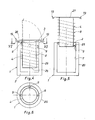
- the room cell (1) has a cell floor (2) and an opposite opening (3) into which a container (4) for waste, bulk, storage goods or the like is inserted.
- the opening (3) is protected against the weather by a protruding cover (5).
- the inner wall (7) of the room cell (l) has a thread spiral (8) as a sliding surface, in which several rollers (9) engage and center, which engage with a bogie (l0) that holds the container (4). are connected.
- the bogie (l0) consists of a plate (ll) with at least three associated supports (l3), extending approximately from the lower end (l2) of the screw thread (8) to the opening (3) of the room cell (l), with the ends facing the floor (2) of the room cell (l) the rollers (9) are provided.
- the plate (II) is circular in shape and the rollers (9) and the supports (l3) are arranged at a uniform radial distance around the plate (ll), offset in the illustrated case by 120 ° from one another, with two adjacent supports (l3) there is a sufficiently large space (l4) for removing and reinserting the container (4) placed on the plate (ll), as can be seen from FIG. 3.
- holding troughs (15) for the rollers (9) are provided at the upper end of the threaded spiral (8) in order to lock them in this position for the removal and re-use of the container (4).
- the lower ends of the supports (l3) are connected to one another by a rigid and torsionally rigid rod (l6) in order in this way to ensure an equal and centering distance between the rollers (9).
- the supports (l3) are provided with a cover (5) which completely protects the opening (3) of the room cell (l) against the weather.
- the cover (5) has a swivel flap (2l) with an insertion shaft (22) directed towards the opened container (4).
- the thread spiral (8) forms a trapezoidal thread and consists either of metal, plastic or - as shown - made of a highly hardened concrete, the sectional structure of which has been omitted for the sake of clarity.
- the loading of the container (s) (4) takes place through the swivel flaps (2l) and the insertion chutes (22).
- the handles (l9, 20) are grasped and moved in the direction of the arrows (23), as a result of which the bogie (l0) and thus the container (4) are set in circular movements.
- the rollers (9) engaging in the thread spiral (8) screw the bogie (l0) together with the container (4) upward in the thread spiral (8) with relatively little effort. Even a load weighing several hundredweight can be moved in this way by a child with a diameter of the thread spiral (8) of, for example, 75 cm and a gradient of 7%.
- the flower bowl (l7) can be replaced by, for example, a small water lily pond or a suitably designed aquarium, eg for goldfish.
- a bird bath or a small fountain on the cover (5) to accommodate the room cell (l) sunk below the floor level (24) to give an appealing, external look.
- FIGS. 4 to 6 The kinematic reversal of the embodiment in FIGS. 1 to 3 is shown in FIGS. 4 to 6.
- the container (4) now has a circular cylindrical shape, which was not necessary in the embodiment of FIGS. 1 to 3.
- the rollers (9) are arranged near the opening (3) on the inner wall (7) of the room cell (l).
- the threaded spiral (8) is advantageously integrally connected to the container (4) and consists of plastic. Due to this nature, the lifting device (4, 8, 9) can be easily operated by hand in both directions with a uniform load and is robust and trouble-free.
- the rollers (9) are provided with automatically acting centrifugal brakes (not shown) in their running direction when the container (4) moves downward from the opening (3) to the floor (2) of the room cell (1).
- the threaded spiral (8) has holding troughs (26) for the rollers (9) in the vicinity of the bottom (25) of the container (4).
- the cover (27) of the container (4) in its position lowered in the room cell (l), completely covers its opening (3) against weather influences and is in this position automatically in its closed position from the upper edge (28) of the room cell (l) transferable.
- the lid (27) of the container (4) is provided with a cover, for example in the form of the bicycle stand (18) according to FIG.
- rollers (9) and / or the base (25) of the container (4) can be rotated hydraulically, pneumatically or electrically, although these design alternatives are not preferable to simple, manual operation because of their greater outlay.
- the room cell (l) consists either of plastic, for example of a glass fiber reinforced polyester, a polyvinyl chloride or the like, or of concrete with a weatherproof bitumen coating on its outer jacket (29).
Landscapes
- Engineering & Computer Science (AREA)
- Mechanical Engineering (AREA)
- Refuse Receptacles (AREA)
- Refuse Collection And Transfer (AREA)
Applications Claiming Priority (2)
| Application Number | Priority Date | Filing Date | Title |
|---|---|---|---|
| DE19863608730 DE3608730A1 (de) | 1986-03-15 | 1986-03-15 | Bodenversenkbare raumzelle mit einem behaelter fuer muell-, schuett- und lagergueter |
| DE3608730 | 1986-03-15 |
Publications (2)
| Publication Number | Publication Date |
|---|---|
| EP0240748A2 true EP0240748A2 (fr) | 1987-10-14 |
| EP0240748A3 EP0240748A3 (fr) | 1989-08-30 |
Family
ID=6296463
Family Applications (1)
| Application Number | Title | Priority Date | Filing Date |
|---|---|---|---|
| EP87103303A Withdrawn EP0240748A3 (fr) | 1986-03-15 | 1987-03-07 | Emplacement souterrain pour un récipient à ordures, un récipient contenant des produits en vrac ou analogues |
Country Status (2)
| Country | Link |
|---|---|
| EP (1) | EP0240748A3 (fr) |
| DE (1) | DE3608730A1 (fr) |
Cited By (4)
| Publication number | Priority date | Publication date | Assignee | Title |
|---|---|---|---|---|
| EP0480326A1 (fr) * | 1990-10-11 | 1992-04-15 | Giancarlo Galeazzi | Dispositif de recueil de déchets |
| EP0659159B2 (fr) † | 1992-09-17 | 2001-03-21 | Metro Waste Systems B.V. | Dispositif de collecte de dechets |
| CN114476434A (zh) * | 2022-01-18 | 2022-05-13 | 张霞 | 一种细胞培养产生的垃圾分类回收装置 |
| US12179999B2 (en) | 2022-03-07 | 2024-12-31 | Earthbin Inc. | In-ground receptacle and installation thereof |
Families Citing this family (5)
| Publication number | Priority date | Publication date | Assignee | Title |
|---|---|---|---|---|
| FR2736901B1 (fr) * | 1995-07-19 | 1997-09-05 | Allibert Equipement | Unite de reception des dechets a mouvement verrouillable/ deverrouillable |
| DE19642989C2 (de) * | 1996-10-18 | 1999-02-25 | Wittenbauer Rudolf Dipl Ing Fh | Abdeckung |
| ES2120900B1 (es) * | 1996-10-21 | 1999-06-01 | Centra Electric S A | Armario de distribucion electrico empotrado en el suelo y extraible. |
| DE19757146C1 (de) * | 1997-12-20 | 1999-02-25 | Ulrich Loetzsch | Aufnahmesystem |
| CN108622581B (zh) * | 2018-06-25 | 2020-09-25 | 安徽一鸣塑胶有限公司 | 一种园林用便于开盖的垃圾桶 |
Family Cites Families (4)
| Publication number | Priority date | Publication date | Assignee | Title |
|---|---|---|---|---|
| DE2431090A1 (de) * | 1974-06-28 | 1976-01-08 | Stadtmueller Otto | Bauweise fuer muellboxen |
| DE2733437A1 (de) * | 1977-07-25 | 1979-02-08 | Schaefer Gmbh Fritz | Muelltonnenschrank oder -box |
| DE3115477C2 (de) * | 1981-04-16 | 1983-08-18 | J. Gärtner Stahlbau GmbH & Co KG, 7502 Malsch | Fünfseitig geschlossene Raumzelle, insbesondere Aufnahmebox für Müllsammelgefäße |
| DE8402849U1 (de) * | 1984-02-01 | 1984-06-07 | Treml, Franz, 7500 Karlsruhe | Bepflanzbarer muelltonnenschrank |
-
1986
- 1986-03-15 DE DE19863608730 patent/DE3608730A1/de active Granted
-
1987
- 1987-03-07 EP EP87103303A patent/EP0240748A3/fr not_active Withdrawn
Cited By (6)
| Publication number | Priority date | Publication date | Assignee | Title |
|---|---|---|---|---|
| EP0480326A1 (fr) * | 1990-10-11 | 1992-04-15 | Giancarlo Galeazzi | Dispositif de recueil de déchets |
| US5140786A (en) * | 1990-10-11 | 1992-08-25 | Giancarlo Galeazzi | Waste collection device |
| EP0659159B2 (fr) † | 1992-09-17 | 2001-03-21 | Metro Waste Systems B.V. | Dispositif de collecte de dechets |
| CN114476434A (zh) * | 2022-01-18 | 2022-05-13 | 张霞 | 一种细胞培养产生的垃圾分类回收装置 |
| CN114476434B (zh) * | 2022-01-18 | 2023-03-31 | 张霞 | 一种细胞培养产生的垃圾分类回收装置 |
| US12179999B2 (en) | 2022-03-07 | 2024-12-31 | Earthbin Inc. | In-ground receptacle and installation thereof |
Also Published As
| Publication number | Publication date |
|---|---|
| EP0240748A3 (fr) | 1989-08-30 |
| DE3608730A1 (de) | 1987-09-17 |
| DE3608730C2 (fr) | 1988-02-11 |
Similar Documents
| Publication | Publication Date | Title |
|---|---|---|
| EP0240748A2 (fr) | Emplacement souterrain pour un récipient à ordures, un récipient contenant des produits en vrac ou analogues | |
| DE2620977A1 (de) | Komposter fuer hausmuell und gartenabfaelle | |
| DE3418830A1 (de) | Altbatterie-sammelbehaelter | |
| DE2614535B2 (de) | Fahrbarer, durch Klappdeckel verschließbarer Müllgroßbehälter | |
| DE29807930U1 (de) | Behälter zum Aufnehmen von Sammelgut | |
| DE3029982A1 (de) | Sammelbehaelter, insbesondere fuer altglas | |
| DE1200206B (de) | Abfallbehaelter | |
| DE29617960U1 (de) | Aufnahmebox für den Unterflureinbau | |
| DE7916034U1 (de) | Sammelbehälter | |
| DE2733752C2 (fr) | ||
| DE9201348U1 (de) | Abfallbehälter | |
| DE8607202U1 (de) | Bodenversenkbare Raumzelle mit einem Behälter für Müll-, Schütt- und Lagergüter | |
| DE4200387A1 (de) | Muellbehaelter-system | |
| DE4039322A1 (de) | Abdeckung fuer einen gewerblich verwendenden transportablen behaelter | |
| CH459878A (de) | Zur Aufnahme von Abfällen bestimmter Haushalts-Treteimer aus Kunststoff | |
| DE2559950C2 (de) | Großraum-Müllsammelbehälter | |
| DE202021100722U1 (de) | Mülltonnenbox und Verwendung einer solchen | |
| DE3447155A1 (de) | Vorrichtung zur beseitigung von hausmuell | |
| DE19613771A1 (de) | Abfallbehälter, insbesondere für den öffentlichen Bereich | |
| DE2204121A1 (de) | Abfallbehaelter | |
| CH249608A (de) | Kehrichteimer mit Aufbewahrungsbehältnis und Vorrichtung zum Ausfahren des Eimers. | |
| DE8118240U1 (de) | "Sammelbehälter mit Bodenentleerung für Feststoffe, insbesondere Altglas" | |
| DE3139112A1 (de) | Schwenkdeckelverschluss von behaeltern | |
| DE202009014293U1 (de) | Abfallcontainer | |
| DE2719739A1 (de) | Schrankartige aufnahme fuer muellbehaelter |
Legal Events
| Date | Code | Title | Description |
|---|---|---|---|
| PUAI | Public reference made under article 153(3) epc to a published international application that has entered the european phase |
Free format text: ORIGINAL CODE: 0009012 |
|
| AK | Designated contracting states |
Kind code of ref document: A2 Designated state(s): AT BE CH DE FR GB IT LI LU NL SE |
|
| PUAL | Search report despatched |
Free format text: ORIGINAL CODE: 0009013 |
|
| AK | Designated contracting states |
Kind code of ref document: A3 Designated state(s): AT BE CH DE FR GB IT LI LU NL SE |
|
| 17P | Request for examination filed |
Effective date: 19900118 |
|
| 17Q | First examination report despatched |
Effective date: 19910306 |
|
| STAA | Information on the status of an ep patent application or granted ep patent |
Free format text: STATUS: THE APPLICATION HAS BEEN WITHDRAWN |
|
| 18W | Application withdrawn |
Withdrawal date: 19910920 |