EP0240812A2 - Système d'emmagasinage - Google Patents
Système d'emmagasinage Download PDFInfo
- Publication number
- EP0240812A2 EP0240812A2 EP87104181A EP87104181A EP0240812A2 EP 0240812 A2 EP0240812 A2 EP 0240812A2 EP 87104181 A EP87104181 A EP 87104181A EP 87104181 A EP87104181 A EP 87104181A EP 0240812 A2 EP0240812 A2 EP 0240812A2
- Authority
- EP
- European Patent Office
- Prior art keywords
- stacking
- pallet
- cheeks
- unstacking
- station
- Prior art date
- Legal status (The legal status is an assumption and is not a legal conclusion. Google has not performed a legal analysis and makes no representation as to the accuracy of the status listed.)
- Granted
Links
Images

Classifications
-
- B—PERFORMING OPERATIONS; TRANSPORTING
- B65—CONVEYING; PACKING; STORING; HANDLING THIN OR FILAMENTARY MATERIAL
- B65G—TRANSPORT OR STORAGE DEVICES, e.g. CONVEYORS FOR LOADING OR TIPPING, SHOP CONVEYOR SYSTEMS OR PNEUMATIC TUBE CONVEYORS
- B65G59/00—De-stacking of articles
- B65G59/06—De-stacking from the bottom of the stack
- B65G59/061—De-stacking from the bottom of the stack articles being separated substantially along the axis of the stack
- B65G59/066—De-stacking from the bottom of the stack articles being separated substantially along the axis of the stack by means of rotary devices or endless elements
-
- B—PERFORMING OPERATIONS; TRANSPORTING
- B65—CONVEYING; PACKING; STORING; HANDLING THIN OR FILAMENTARY MATERIAL
- B65G—TRANSPORT OR STORAGE DEVICES, e.g. CONVEYORS FOR LOADING OR TIPPING, SHOP CONVEYOR SYSTEMS OR PNEUMATIC TUBE CONVEYORS
- B65G61/00—Use of pick-up or transfer devices or of manipulators for stacking or de-stacking articles not otherwise provided for
Definitions
- the invention relates to a magazine system for mechanically loading and / or unloading pallets, workpiece carriers, transport boxes or the like according to the preamble of claim 1.
- the known device has the disadvantage that each device is only adapted to a certain pallet size, i. H. pallets of different sizes cannot be used.
- the invention has for its object to develop a device of the type mentioned in such a way that it can be used universally for a wide variety of standard sizes, especially the so-called European pallets.
- the main idea of the present invention is to construct the device according to the invention in a special modular system, in order in particular to be able to process a wide variety of pallet sizes with one and the same basic unit.
- the device is supplied in a certain basic size, in particular for a European pallet standard. Any intermediate sizes of pallets can be integrated into the system by adapting the width of the device according to the invention to the pallet size. This also applies to different heights of the pallets.
- the side parts or stacking cheeks can be removed from the basic unit, so that an adapter element can be used to widen the device. Since the drive means, in particular the cam disks, are located in the side stacking cheeks, they can also be exchanged to adapt to different sized pallet shapes. This creates a system that can be used as universally as possible and also covers intermediate sizes of pallets. If a certain growing width is exceeded, the broad side is made the long side in the next larger system when the next standard size of the European pallet standard is reached.
- the cam disks in the stacking cheek are connected to one another via a chain drive. This provides an extremely economical solution (high precision) between the direct linking of the unstacking or stacking station.
- the embodiment of the invention according to subclaim 3 has the advantage in connection with the measures according to subclaim 2 that a single drive is provided for all cam disks, regardless of whether different width versions of the magazine system are used. For this purpose, a thru-axle adapted in width is used as the drive axle.
- the horizontal and vertical guide strips designed according to subclaim 4 in conjunction with claim 6 enable the pallets to be positioned with the greatest possible precision with minimal effort.
- the selected bevel on both the vertical guide bar and the associated parts of the pallet can save additional guide surfaces.
- the formation of the pallet spacers according to subclaims 5 and 6 also has the advantage that an exact stackability of the pallets with precise indexing is made possible in a very simple manner.
- control unit is according to d P r training according to subclaim 7 is designed as an insert which extends through the various stacking cheeks and adapters.
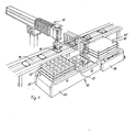
- the magazine system (10) consists of a stacking station (11) and an unstacking station (12) and a transport unit or processing station (13) located in between.
- workpieces (14) are picked up by a handling machine (15) from a conveyor belt (16) the pallets (17) are placed in the area of the transport or processing station (13).
- empty pallets (17 1 ) are removed from the unstacking station (12) and full pallets (17 '') filled with workpieces (14) are stored in the stacking station (11) in a manner known per se in a memory designed as a vertical conveyor.
- the programming and control unit (18) controls the precise unstacking and stacking process of the stations (12, 11) and the further transport of the pallets between the stations.
- the magazine system (10) is constructed as a modular system.
- the device consists of a basic unit (19) which has a certain width b l .
- the side version of a left (20) and right (21) stacking cheek produces the basic version as shown in FIG. 1.
- the cam disks (22) are integrated into the stacking cheeks themselves.
- the drive unit (23) with the drive axle (24) is located in the base unit (19).
- the conveyor (25) with the transport unit (13) is integrated in the basic unit.
- the left stacking cheek (20) contains a push-through opening (26) in the front area of the unstacking station (12), which extends into an opening (27) in the base unit (19) for receiving the control unit (18).
- the basic unit (19) accordingly contains all drive and query elements for the overall system.
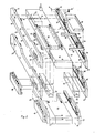
- FIG. 2 also shows a pallet frame (28) with a deep-drawing cassette (29) to be picked up by it.
- the side webs (30) of the pallet frame (28) can have different widths.
- the modular system enables the inclusion of additional adapter elements (31, 32) for widening the basic unit (19) to a pallet width to, for example, b 2 .
- the side stacking cheeks (20, 21) are removed from the side and the adapter elements (31, 31) are inserted in the desired width b 3 .
- the adapter elements (31, 32) can take any intermediate dimension.
- a corresponding through opening (33) in the left adapter element (31) enables the control unit (18) to be inserted subsequently.
- the device is designed in such a way that the stacking or unstacking process as well as the transport process can also take place in the opposite direction or sequence, so that the magazine system can be used as a buffer or memory.
- the side stacking cheeks (20, 21) can vary in size. This is shown with the additional reference numerals (20 'and 21').
- the stacking cheeks (20, 21) have, for example, the overall height h 1
- the stacking cheeks (20 ', 21') have the overall height h 2 in the region of the loading and unstacking station (11, 12).
- the cam disks (22) are also of different sizes, which is indicated by the reference symbol (22 ') for the smaller cam disks.
- the vertical guide rails (36) are also shown in FIG. 2.
- the drive shown in FIG. 2 takes place via the drive unit (23) on the drive axle (24) and thus on the drive pinion (38) shown in FIG. 3.
- An additional chain tensioning wheel (39) is used to correctly tension the drive chain (37).
- the respective cam disks (22) In the stacking and unstacking station (11) or (12) the respective cam disks (22) must work in the opposite direction. This is done by means of deflection wheels (40) which reverse the direction of rotation of the cam disks, which are directed towards the transport unit (13).
- the left control unit shown in (11) in FIG. 3 therefore rotates counterclockwise, the right control clockwise.
- FIG. 4 A detailed representation of the invention is shown in FIG. 4.
- the right stacking cheek (21) of the unstacking station (12) is shown here.
- the cam disks (22) rotating in the opposite direction have driver pins (34). The direction of rotation is marked with the arrows (41).
- the pallet frames (28) shown in partial view are variably connected in width by means of the side webs (30).
- the pallets are stacked using the trapezoidal pallet spacers (42), each of which has a right-angled tab (43) at its lower end.
- An opening (44) in the lower region of the spacer (42) or in a part of the tab (43) enables the respective upper part of the spacer (42) to engage in the opening of the spacer above it. This is shown again in section in FIG. 5.
- This bevel (45) engages in a correspondingly adapted bevel (46) on the vertical guide bar (36). This is symbolized in FIG. 4 by the two dashed lines (46).
- This 45 ° bevel (45, 46) on the parts (42, 36) enables sufficient indexing, ie positioning of the pallet frames (28, 30), with only four guide surfaces.
- the stacking cam (34) can directly reach under the pallet spacers in this area. This is indicated in Fig. 5 with the stacking force F.
- the flow of force remains in the stack tabs according to arrow (47).
- the pallet frame can have a very light construction.
- the tabs (43) are therefore designed at the same time as indexing tabs in connection with the vertical guide rails (36) and as stacking tabs in connection with the driving pins (34).
Landscapes
- Stacking Of Articles And Auxiliary Devices (AREA)
- De-Stacking Of Articles (AREA)
- Centrifugal Separators (AREA)
- Sampling And Sample Adjustment (AREA)
- Separation By Low-Temperature Treatments (AREA)
- Valve Device For Special Equipments (AREA)
- Iron Core Of Rotating Electric Machines (AREA)
- Valve-Gear Or Valve Arrangements (AREA)
Priority Applications (1)
| Application Number | Priority Date | Filing Date | Title |
|---|---|---|---|
| AT87104181T ATE53369T1 (de) | 1986-04-11 | 1987-03-21 | Magazinier-system. |
Applications Claiming Priority (2)
| Application Number | Priority Date | Filing Date | Title |
|---|---|---|---|
| DE3612202 | 1986-04-11 | ||
| DE19863612202 DE3612202A1 (de) | 1986-04-11 | 1986-04-11 | Magazinier-system |
Publications (3)
| Publication Number | Publication Date |
|---|---|
| EP0240812A2 true EP0240812A2 (fr) | 1987-10-14 |
| EP0240812A3 EP0240812A3 (en) | 1988-08-10 |
| EP0240812B1 EP0240812B1 (fr) | 1990-06-06 |
Family
ID=6298466
Family Applications (1)
| Application Number | Title | Priority Date | Filing Date |
|---|---|---|---|
| EP87104181A Expired - Lifetime EP0240812B1 (fr) | 1986-04-11 | 1987-03-21 | Système d'emmagasinage |
Country Status (3)
| Country | Link |
|---|---|
| EP (1) | EP0240812B1 (fr) |
| AT (1) | ATE53369T1 (fr) |
| DE (2) | DE3612202A1 (fr) |
Cited By (5)
| Publication number | Priority date | Publication date | Assignee | Title |
|---|---|---|---|---|
| DE3915139A1 (de) * | 1989-05-09 | 1990-11-15 | Focke & Co | Verfahren und anlage zum umordnen von sortenweise palettierten gegenstaenden zu gruppen bestimmter sortenzusammenstellung |
| US5269646A (en) * | 1989-05-09 | 1993-12-14 | Focke & Co. (Gmbh & Co.) | Process and installation for the rearrangement of articles palletised according to sorts to form groups of specific sort composition |
| US5536137A (en) * | 1994-03-21 | 1996-07-16 | Felsomat Gmbh & Co. Kg | Handling system and method |
| US10358301B2 (en) | 2012-10-31 | 2019-07-23 | Beumer Group A/S | Method of distributing airport baggage |
| CN116853801A (zh) * | 2023-09-01 | 2023-10-10 | 常州孟腾智能装备有限公司 | 电芯托盘解锁机构及其输送线 |
Families Citing this family (1)
| Publication number | Priority date | Publication date | Assignee | Title |
|---|---|---|---|---|
| DE102010032604A1 (de) * | 2010-07-28 | 2012-02-02 | Metzger & Becker Gmbh | Vorrichtung und Verfahren zum Zwischenspeichern von unlackierten Dosen |
Family Cites Families (3)
| Publication number | Priority date | Publication date | Assignee | Title |
|---|---|---|---|---|
| DE1127810B (de) * | 1960-12-21 | 1962-04-12 | Hesser Ag Maschf | Vorrichtung zum Stapeln von prismatischen Gegenstaenden, insbesondere in Verbindung mit einer Einrichtung zum Sammelpacken der gestapelten Gegenstaende |
| DE2206437C3 (de) * | 1972-02-11 | 1975-03-20 | Focke & Pfuhl Verpackungsautomaten, Sonderkonstruktionen, 3090 Verden | Vorrichtung zum Heben von durch einen Förderer zugeführten Gegenständen, insbesondere quaderförmigen Packungen |
| DE3337374A1 (de) * | 1983-10-14 | 1985-04-25 | Franz 7988 Wangen Biggel | Vorrichtung zum mechanischen ent- und/oder bestapeln von paletten oder dergleichen |
-
1986
- 1986-04-11 DE DE19863612202 patent/DE3612202A1/de not_active Withdrawn
-
1987
- 1987-03-21 EP EP87104181A patent/EP0240812B1/fr not_active Expired - Lifetime
- 1987-03-21 AT AT87104181T patent/ATE53369T1/de not_active IP Right Cessation
- 1987-03-21 DE DE8787104181T patent/DE3763060D1/de not_active Expired - Lifetime
Cited By (7)
| Publication number | Priority date | Publication date | Assignee | Title |
|---|---|---|---|---|
| DE3915139A1 (de) * | 1989-05-09 | 1990-11-15 | Focke & Co | Verfahren und anlage zum umordnen von sortenweise palettierten gegenstaenden zu gruppen bestimmter sortenzusammenstellung |
| EP0396960A3 (fr) * | 1989-05-09 | 1991-02-06 | Focke & Co. (GmbH & Co.) | Méthode et installation pour réarranger des objets palettisés par sortes en groupes dont la composition des sortes est définie |
| US5269646A (en) * | 1989-05-09 | 1993-12-14 | Focke & Co. (Gmbh & Co.) | Process and installation for the rearrangement of articles palletised according to sorts to form groups of specific sort composition |
| US5536137A (en) * | 1994-03-21 | 1996-07-16 | Felsomat Gmbh & Co. Kg | Handling system and method |
| US10358301B2 (en) | 2012-10-31 | 2019-07-23 | Beumer Group A/S | Method of distributing airport baggage |
| CN116853801A (zh) * | 2023-09-01 | 2023-10-10 | 常州孟腾智能装备有限公司 | 电芯托盘解锁机构及其输送线 |
| CN116853801B (zh) * | 2023-09-01 | 2023-12-08 | 常州孟腾智能装备有限公司 | 电芯托盘解锁机构及其输送线 |
Also Published As
| Publication number | Publication date |
|---|---|
| EP0240812B1 (fr) | 1990-06-06 |
| DE3612202A1 (de) | 1987-10-15 |
| EP0240812A3 (en) | 1988-08-10 |
| DE3763060D1 (de) | 1990-07-12 |
| ATE53369T1 (de) | 1990-06-15 |
Similar Documents
| Publication | Publication Date | Title |
|---|---|---|
| DE69207737T2 (de) | Einrichtung zum Handhaben und Ausrichten von gebündelten flachen Gegenständen | |
| DE2950292A1 (de) | Einrichtung zum ausrichten und festspannen eines werkstuecktraegers | |
| DE2611556A1 (de) | Automatisches sortierfoerdersystem | |
| EP0272751A2 (fr) | Machine d'assemblage pour un emballage | |
| DE3731497A1 (de) | Spulentellertransportvorrichtung | |
| DE3345920A1 (de) | Einrichtung zum automatischen transport von werkstuecken | |
| DE3403550C2 (de) | Transport- und Lagergestell | |
| EP0240812B1 (fr) | Système d'emmagasinage | |
| DE4315314A1 (de) | Vorrichtung zum Ändern der Stellung eines Deckels | |
| EP2165952B1 (fr) | Dispositif de séparation | |
| DE4025368A1 (de) | Stapelmagazin fuer flaschenkaesten o. dgl. transportkaesten | |
| DE2717586C2 (de) | Ortsbeweglicher Speicher zur Aufnahme und zum Transport von Werkstücken | |
| DE2149965C2 (de) | Montagemaschine für Möbelbeschläge, insbesondere Scharniere | |
| EP0378778A1 (fr) | Dispositif de stockage à chaîne | |
| DE3337374A1 (de) | Vorrichtung zum mechanischen ent- und/oder bestapeln von paletten oder dergleichen | |
| DE3150190A1 (de) | "stapelvorrichtung fuer papier- oder kunststoffsaecke" | |
| DE3403909C2 (de) | Vorrichtung zum Transportieren und Ausrichten von aufeinanderfolgenden flachen Gegenständen | |
| DE3400332C1 (de) | Hubstation zur Verwendung bei Friktionsrollenbahnen oder anderen Förderern | |
| DE1940287A1 (de) | Automatische Abfuell- und Verschliessmaschine | |
| DE2438812A1 (de) | Vorrichtung zum selbsttaetigen befoerdern eines zu bearbeitenden gegenstandes zwischen zwei werkzeugmaschinen | |
| EP0212055B1 (fr) | Dispositif pour changer rapidement les rails de guidage d'un convoyeur | |
| DE3406293A1 (de) | Stapelbehaelter fuer formteile, insbesondere blech-stanzteile | |
| EP0602415A1 (fr) | Dispositif de chargement et déchargement pour le traitement d'objets en forme de plaque | |
| EP0293324A2 (fr) | Dispositif d'empilage | |
| DE3448491C2 (de) | Fördereinrichtung, insbesondere für eine Montagemaschine |
Legal Events
| Date | Code | Title | Description |
|---|---|---|---|
| PUAI | Public reference made under article 153(3) epc to a published international application that has entered the european phase |
Free format text: ORIGINAL CODE: 0009012 |
|
| AK | Designated contracting states |
Kind code of ref document: A2 Designated state(s): AT BE CH DE ES FR GB IT LI NL SE |
|
| PUAL | Search report despatched |
Free format text: ORIGINAL CODE: 0009013 |
|
| AK | Designated contracting states |
Kind code of ref document: A3 Designated state(s): AT BE CH DE ES FR GB IT LI NL SE |
|
| 17P | Request for examination filed |
Effective date: 19881207 |
|
| 17Q | First examination report despatched |
Effective date: 19890403 |
|
| GRAA | (expected) grant |
Free format text: ORIGINAL CODE: 0009210 |
|
| AK | Designated contracting states |
Kind code of ref document: B1 Designated state(s): AT BE CH DE ES FR GB IT LI NL SE |
|
| PG25 | Lapsed in a contracting state [announced via postgrant information from national office to epo] |
Ref country code: SE Effective date: 19900606 Ref country code: NL Effective date: 19900606 Ref country code: GB Effective date: 19900606 Ref country code: BE Effective date: 19900606 |
|
| REF | Corresponds to: |
Ref document number: 53369 Country of ref document: AT Date of ref document: 19900615 Kind code of ref document: T |
|
| REF | Corresponds to: |
Ref document number: 3763060 Country of ref document: DE Date of ref document: 19900712 |
|
| ITF | It: translation for a ep patent filed | ||
| ET | Fr: translation filed | ||
| PG25 | Lapsed in a contracting state [announced via postgrant information from national office to epo] |
Ref country code: ES Free format text: LAPSE BECAUSE OF FAILURE TO SUBMIT A TRANSLATION OF THE DESCRIPTION OR TO PAY THE FEE WITHIN THE PRESCRIBED TIME-LIMIT Effective date: 19900917 |
|
| NLV1 | Nl: lapsed or annulled due to failure to fulfill the requirements of art. 29p and 29m of the patents act | ||
| GBV | Gb: ep patent (uk) treated as always having been void in accordance with gb section 77(7)/1977 [no translation filed] | ||
| PG25 | Lapsed in a contracting state [announced via postgrant information from national office to epo] |
Ref country code: AT Effective date: 19910321 |
|
| PLBE | No opposition filed within time limit |
Free format text: ORIGINAL CODE: 0009261 |
|
| STAA | Information on the status of an ep patent application or granted ep patent |
Free format text: STATUS: NO OPPOSITION FILED WITHIN TIME LIMIT |
|
| 26N | No opposition filed | ||
| ITTA | It: last paid annual fee | ||
| PGFP | Annual fee paid to national office [announced via postgrant information from national office to epo] |
Ref country code: FR Payment date: 19950411 Year of fee payment: 9 |
|
| PGFP | Annual fee paid to national office [announced via postgrant information from national office to epo] |
Ref country code: CH Payment date: 19950523 Year of fee payment: 9 |
|
| PG25 | Lapsed in a contracting state [announced via postgrant information from national office to epo] |
Ref country code: LI Effective date: 19960331 Ref country code: CH Effective date: 19960331 |
|
| PGFP | Annual fee paid to national office [announced via postgrant information from national office to epo] |
Ref country code: DE Payment date: 19960525 Year of fee payment: 10 |
|
| REG | Reference to a national code |
Ref country code: CH Ref legal event code: PL |
|
| PG25 | Lapsed in a contracting state [announced via postgrant information from national office to epo] |
Ref country code: FR Effective date: 19961129 |
|
| REG | Reference to a national code |
Ref country code: FR Ref legal event code: ST |
|
| PG25 | Lapsed in a contracting state [announced via postgrant information from national office to epo] |
Ref country code: DE Effective date: 19971202 |
|
| PG25 | Lapsed in a contracting state [announced via postgrant information from national office to epo] |
Ref country code: IT Free format text: LAPSE BECAUSE OF NON-PAYMENT OF DUE FEES;WARNING: LAPSES OF ITALIAN PATENTS WITH EFFECTIVE DATE BEFORE 2007 MAY HAVE OCCURRED AT ANY TIME BEFORE 2007. THE CORRECT EFFECTIVE DATE MAY BE DIFFERENT FROM THE ONE RECORDED. Effective date: 20050321 |