EP0240875B1 - Dispositif de test de la résistance de contact entre une source d'énergie et un appareil électrique reliés par un connecteur électrique - Google Patents
Dispositif de test de la résistance de contact entre une source d'énergie et un appareil électrique reliés par un connecteur électrique Download PDFInfo
- Publication number
- EP0240875B1 EP0240875B1 EP87104602A EP87104602A EP0240875B1 EP 0240875 B1 EP0240875 B1 EP 0240875B1 EP 87104602 A EP87104602 A EP 87104602A EP 87104602 A EP87104602 A EP 87104602A EP 0240875 B1 EP0240875 B1 EP 0240875B1
- Authority
- EP
- European Patent Office
- Prior art keywords
- series branch
- switch
- contact resistance
- resistance
- capacitor
- Prior art date
- Legal status (The legal status is an assumption and is not a legal conclusion. Google has not performed a legal analysis and makes no representation as to the accuracy of the status listed.)
- Expired - Lifetime
Links
- 238000012360 testing method Methods 0.000 title claims description 25
- 238000004146 energy storage Methods 0.000 claims abstract description 6
- 239000003990 capacitor Substances 0.000 claims description 22
- 230000008878 coupling Effects 0.000 claims description 4
- 238000010168 coupling process Methods 0.000 claims description 4
- 238000005859 coupling reaction Methods 0.000 claims description 4
- 238000005259 measurement Methods 0.000 abstract description 12
- 230000008901 benefit Effects 0.000 description 3
- 238000011156 evaluation Methods 0.000 description 2
- 238000012544 monitoring process Methods 0.000 description 2
- 230000007704 transition Effects 0.000 description 2
- 238000012935 Averaging Methods 0.000 description 1
- 230000000903 blocking effect Effects 0.000 description 1
- 238000005260 corrosion Methods 0.000 description 1
- 230000007797 corrosion Effects 0.000 description 1
- 238000011161 development Methods 0.000 description 1
- 230000000694 effects Effects 0.000 description 1
- 230000005611 electricity Effects 0.000 description 1
- 238000005265 energy consumption Methods 0.000 description 1
- 230000010354 integration Effects 0.000 description 1
- 238000000034 method Methods 0.000 description 1
- 230000008569 process Effects 0.000 description 1
- 230000004044 response Effects 0.000 description 1
- 239000004065 semiconductor Substances 0.000 description 1
- 238000010998 test method Methods 0.000 description 1
Images
Classifications
-
- G—PHYSICS
- G01—MEASURING; TESTING
- G01R—MEASURING ELECTRIC VARIABLES; MEASURING MAGNETIC VARIABLES
- G01R27/00—Arrangements for measuring resistance, reactance, impedance, or electric characteristics derived therefrom
- G01R27/02—Measuring real or complex resistance, reactance, impedance, or other two-pole characteristics derived therefrom, e.g. time constant
- G01R27/20—Measuring earth resistance; Measuring contact resistance, e.g. of earth connections, e.g. plates
- G01R27/205—Measuring contact resistance of connections, e.g. of earth connections
-
- G—PHYSICS
- G01—MEASURING; TESTING
- G01R—MEASURING ELECTRIC VARIABLES; MEASURING MAGNETIC VARIABLES
- G01R27/00—Arrangements for measuring resistance, reactance, impedance, or electric characteristics derived therefrom
- G01R27/02—Measuring real or complex resistance, reactance, impedance, or other two-pole characteristics derived therefrom, e.g. time constant
- G01R27/14—Measuring resistance by measuring current or voltage obtained from a reference source
Definitions
- the invention relates to a test device according to the preamble of claim 1.
- An energy store e.g. a backup battery, an auxiliary power supply or a buffer capacitor is often connected to the associated electrical device via connecting terminals, which enable simple replacement of the energy store.
- the invention is based on the finding that the contact resistances of the connection terminals of such energy stores increase so much due to faulty exchange or corrosion that the function of the energy store is questioned. This effect is particularly evident in the case of energy stores which are only intended for occasional or even one-time power consumption and over which there is therefore no power consumption for extended periods.
- the invention is therefore based on the object of monitoring the contact resistances of the terminals of the energy store in a test device of the type mentioned in a simple manner.
- the test part is a series branch which consists of a switch and an ohmic resistor. All types of mechanical come as switches as well as electromagnetic switches and also semiconductor switches in question.
- the switch can be actuated manually or by a command generator that issues the switch-specific control command.
- the measuring process is as follows: When the switch is open, the full voltage of the energy store is above the series branch, since no current can flow in the series branch. Only after the switch has been closed does a current flow from the energy store via the contact resistances of its terminals and the resistance of the series branch. The resulting voltage jump at the series branch is recorded by an evaluator who uses it to calculate the size of the contact resistance of the terminals.
- the evaluator could e.g. be a threshold value level that taps the voltage at the series branch.
- the threshold level is e.g. set so that it responds when the contact resistance and thus the voltage jump at the series branch exceeds a permissible limit. The response of the threshold value signalizes that the contact resistances are too high.
- Another advantage of the proposed test device is that the level of the voltage of the energy store is included in the contact resistance measurement and can therefore also be monitored.
- test device for measuring the resistance of an element during its operation is known from US-A-3731189.
- This test device has a series branch which contains a switch and the resistance to be measured. Means are provided to operate the switch, a voltage jump occurring at the series branch when this switch is closed. This The voltage jump is then forwarded to an evaluator connected to the series branch, so that a measure of the resistance to be measured can be determined from the voltage jump.
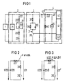
- the electrical device 1 is the trigger circuit for a motor vehicle airbag system.
- the ignition energy for triggering the airbag is supplied by an energy source 2.
- It contains a cascade circuit 21 and a capacitor 220 connected in parallel as an energy store 22, which is designed as an electrolytic capacitor.
- the cascade circuit 21 transforms the DC voltage of a motor vehicle battery to a sufficiently high value and represents a voltage source with such high internal resistance that it can charge the capacitor 220 with a large time constant, but is not able to power the ignition of the Airbag system. For the same reason, their influence is neglected in the following description of the test procedure.
- the capacitor 220 Only the charged capacitor 220 is used as the energy store 22 for the ignition energy of the airbag system. Because of its limited service life, it is connected as a replaceable part via terminals 221 by means of screw connections. Since the presence and the low-resistance integration of the capacitor 220 is a prerequisite for the function of the airbag system, there is a need to monitor the partial contact resistances 222 of the connection terminals 221.
- the contact resistance 223 is understood to be the resistance which corresponds to the sum of the two partial resistors 222 of the two connection terminals 221.
- the monitoring part for the contact resistance 223 consists of a test part 3 and an evaluator 4 with an input 40.
- the input 40 is connected to the test part 3 via a coupling capacitor 5.
- the test part 3 which is connected in parallel to the capacitor 220, consists of a series branch 31, the one Resistor 311, a switch 312 and a parallel circuit comprising a capacitor 313 and a resistor 314.
- switch 312 is a transistor. It is blocked in normal operation and is only turned on briefly by the evaluator 4 for measurement.
- FIG. 2 shows the voltage mesh across the capacitor 220, its contact resistance 223 and the series branch 31 when switch 312 is open and FIG. 3 shows the same voltage mesh immediately after switch 312 is closed.
- the voltage jump ⁇ U31 that occurs during measurement therefore allows the contact resistance 223 to be calculated directly.
- Equation 1 in another notation reads:
- the voltage jump ⁇ U31 is therefore greater, the smaller is. Since impermissible values of the contact resistance 223 are still very small, the resistance 311 is chosen to be approximately the same as this casual transition resistance 223 in order to obtain a significant voltage jump ⁇ U31. However, this dimensioning would result in a large current during the measurement through the series branch 31 and thus a large load on the capacitor 220 and the transistor.
- the small-sized capacitor 313 represents a short circuit the first time after the switch 312 is closed, so that it does not hinder the actual measurement. However, since it is quickly charged, it stops the flow of electricity again. Only a small residual current can then flow through the series circuit 31 via the large parallel resistor 314. After the transistor interrupts the series circuit 31 again, the capacitor 313 discharges through its parallel resistor 314 and thus restores the initial state.
- the evaluator 4 contains a microprocessor 41, on the input side of which is connected an analog-digital converter 42 with an input 421.
- the analog-digital converter 42 requires a reference voltage, which is formed with the aid of a voltage source 44 and a voltage divider, consisting of the resistors 441 and 442. This reference voltage is thus present at the input 421 and the voltage jump from the series branch 31 is superimposed on it.
- the coupling capacitor 5 separates the potentials of the reference voltage and the voltage on the capacitor 220.
- An output of the microprocessor 41 is connected to the base of the transistor which is used as a switch 312 in the test part.
- a single measurement of the contact resistance the 223 is done by switching through once and then blocking the transistor via this output.
- the microprocessor 41 carries out five such individual measurements in quick succession and forms an average value therefrom. This averaging has the advantage of eliminating any errors that can occur in individual measurements.
- the measurement result is finally compared with a limit value and a signal is generated if the measured value exceeds the limit value, ie the contact resistance 223 assumes an impermissible value.
- the indicator signal controls a display part 43 with an LED such that when the LED lights up it signals a proper contact resistance 223.
- test device namely the low energy consumption of a single measurement, allows the measuring intervals to be repeated periodically.
- the microprocessor 41 carries out a measurement interval every ten seconds, ie the contact resistance 223 is monitored periodically and thus the operational safety of the airbag system is significantly improved.
Landscapes
- Physics & Mathematics (AREA)
- General Physics & Mathematics (AREA)
- Measurement Of Resistance Or Impedance (AREA)
- Testing Of Short-Circuits, Discontinuities, Leakage, Or Incorrect Line Connections (AREA)
- Secondary Cells (AREA)
- Electric Double-Layer Capacitors Or The Like (AREA)
- Testing Electric Properties And Detecting Electric Faults (AREA)
- Branch Pipes, Bends, And The Like (AREA)
- Cable Accessories (AREA)
Claims (6)
- Dispositif d'essai pour une résistance de contact (223) de bornes de raccordement (221), par l'intermédiaire desquelles un accumulateur d'énergie (22) est relié à un appareil électrique (1), caractérisé par le fait qu'une unité d'essai (3) est branchée en parallèle avec l'accumulateur d'énergie (24), par l'intermédiaire des bornes de raccordement (221),
que l'unité d'essai (3) contient une branche série (31) incluant un interrupteur (312) et une résistance (311), qu'il est prévu des moyens pour actionner l'interrupteur (312), auquel cas, lors de la fermeture de cet interrupteur (312), un saut de tension apparaît dans la branche série (31),
qu'une extrémité de la branche série (31) de l'unité d'essai (3) est raccordée à une entrée (40) d'un dispositif d'évaluation (4), qui détermine, à partir du saut de tension dans la branche série (31), une mesure de la résistance de contact (223), et
que l'autre extrémité de la branche série (31) de l'unité d'essai (3) est raccordée à l'autre entrée du dispositif d'évaluation (4). - Dispositif d'essai suivant la revendication 1, caractérisé par le fait que la branche série (31) contient en outre un condensateur (313) en parallèle, avec lequel est branchée une résistane (314).
- Dispositif d'essai suivant la revendication 1 ou 2, caractérisé par le fait que le dispositif d'évaluation (4) contient un microprocesseur (41) qui commande également l'interrupteur (312) de l'unité d'essai (3).
- Dispositif d'essai suivant la revendication 3, caractérisé par le fait que l'unité d'essai (3) est raccordée par l'intermédiaire d'un condensateur de couplage (5) à une entrée (40) du dispositif d'évaluation (4).
- Dispositif d'essai suivant la revendication 1, caractérisé par le fait que l'accumulateur d'énergie (21) est un condensateur (220)
- Dispositif d'essai suivant la revendication 1, caractérisé par le fait que l'interrupteur (312) est un transistor.
Priority Applications (1)
| Application Number | Priority Date | Filing Date | Title |
|---|---|---|---|
| AT87104602T ATE60952T1 (de) | 1986-04-07 | 1987-03-27 | Pruefeinrichtung fuer den uebergangswiderstand von anschlussklemmen ueber die ein energiespeicher mit einem elektrischen geraet verbunden ist. |
Applications Claiming Priority (2)
| Application Number | Priority Date | Filing Date | Title |
|---|---|---|---|
| DE3611562 | 1986-04-07 | ||
| DE3611562 | 1986-04-07 |
Publications (2)
| Publication Number | Publication Date |
|---|---|
| EP0240875A1 EP0240875A1 (fr) | 1987-10-14 |
| EP0240875B1 true EP0240875B1 (fr) | 1991-02-20 |
Family
ID=6298087
Family Applications (1)
| Application Number | Title | Priority Date | Filing Date |
|---|---|---|---|
| EP87104602A Expired - Lifetime EP0240875B1 (fr) | 1986-04-07 | 1987-03-27 | Dispositif de test de la résistance de contact entre une source d'énergie et un appareil électrique reliés par un connecteur électrique |
Country Status (7)
| Country | Link |
|---|---|
| US (1) | US4801864A (fr) |
| EP (1) | EP0240875B1 (fr) |
| JP (1) | JPS62245164A (fr) |
| AT (1) | ATE60952T1 (fr) |
| CA (1) | CA1279697C (fr) |
| DE (1) | DE3768039D1 (fr) |
| ES (1) | ES2020213B3 (fr) |
Families Citing this family (4)
| Publication number | Priority date | Publication date | Assignee | Title |
|---|---|---|---|---|
| US5057772A (en) * | 1990-05-29 | 1991-10-15 | Electro Scientific Industries, Inc. | Method and system for concurrent electronic component testing and lead verification |
| NO312925B1 (no) * | 2001-05-08 | 2002-07-15 | Sintef Energiforskning As | Kontaktkontroll |
| DE102015221725A1 (de) * | 2015-11-05 | 2017-05-11 | Robert Bosch Gmbh | Verfahren zum Überwachen eines elektrischen Bordnetzes |
| JP7153458B2 (ja) * | 2018-03-26 | 2022-10-14 | ラピスセミコンダクタ株式会社 | 半導体装置及び電子機器 |
Family Cites Families (5)
| Publication number | Priority date | Publication date | Assignee | Title |
|---|---|---|---|---|
| US3731189A (en) * | 1970-05-15 | 1973-05-01 | Anderson Power Products | Pulse sampling resistance metering method and means |
| US4104578A (en) * | 1976-11-10 | 1978-08-01 | Westinghouse Electric Corp. | Portable digital ohmmeter |
| SU661410A1 (ru) * | 1977-04-04 | 1979-05-05 | Войсковая Часть 36982 | Способ определени переходного сопротивлени контактной пары разрывного типа |
| US4251811A (en) * | 1979-12-26 | 1981-02-17 | Rca Corporation | Battery test system, as for smoke detector alarm |
| US4491797A (en) * | 1982-06-01 | 1985-01-01 | Northern Telecom Limited | Test contact resistance of dry circuit contacts |
-
1987
- 1987-03-27 EP EP87104602A patent/EP0240875B1/fr not_active Expired - Lifetime
- 1987-03-27 AT AT87104602T patent/ATE60952T1/de not_active IP Right Cessation
- 1987-03-27 DE DE8787104602T patent/DE3768039D1/de not_active Expired - Lifetime
- 1987-03-27 ES ES87104602T patent/ES2020213B3/es not_active Expired - Lifetime
- 1987-04-03 JP JP62082758A patent/JPS62245164A/ja active Pending
- 1987-04-06 CA CA000533893A patent/CA1279697C/fr not_active Expired - Lifetime
- 1987-04-07 US US07/035,468 patent/US4801864A/en not_active Expired - Fee Related
Also Published As
| Publication number | Publication date |
|---|---|
| US4801864A (en) | 1989-01-31 |
| JPS62245164A (ja) | 1987-10-26 |
| EP0240875A1 (fr) | 1987-10-14 |
| CA1279697C (fr) | 1991-01-29 |
| DE3768039D1 (de) | 1991-03-28 |
| ATE60952T1 (de) | 1991-03-15 |
| ES2020213B3 (es) | 1991-08-01 |
Similar Documents
| Publication | Publication Date | Title |
|---|---|---|
| EP3503343B1 (fr) | Système électrique et procédé de diagnostic de la capacité de fonctionnement du relais de puissance dans un système électrique | |
| EP0514839B1 (fr) | Circuit pour mesurer la capacité | |
| DE4130978C2 (de) | Verfahren zum Prüfen von elektrischen, abgesicherten Verbrauchern in einem Fahrzeug-Bordnetz | |
| DE4109586A1 (de) | Schaltungsanordnung zur isolationsueberwachung ungeerdeter niederspannungsnetze | |
| DE2703880A1 (de) | Elektrisches pruefgeraet mit akustischer, quantitativer und qualitativer analoganzeige | |
| DE10118189A1 (de) | Verfahren und Vorrichtung zum Abfragen eines Schaltzustandes eines Schalters | |
| EP0240875B1 (fr) | Dispositif de test de la résistance de contact entre une source d'énergie et un appareil électrique reliés par un connecteur électrique | |
| WO1990000255A1 (fr) | Procede et dispositif de controle d'un systeme d'accumulateurs | |
| DE3439015C2 (fr) | ||
| DE4232720C1 (de) | Anordnung zur Funktionsüberwachung und Meßwertauswertung von Füllstands-Sensoren, insbesondere Vibrations-Füllstands-Grenzschaltern | |
| DE3827045A1 (de) | Verpolungsschutzeinrichtung fuer akkuladegeraete | |
| DE3402845A1 (de) | Baugruppeneinschub | |
| EP2117094B1 (fr) | Commutation de surveillance et procédé de contrôle d'une commutation | |
| EP3314275B1 (fr) | Dispositif de mesure pour l'identification d'une fonction déficiente dans un dispositif accumulateur d'énergie | |
| AT393916B (de) | Verfahren zum ueberwachen der isolationswiderstaende einer schar von baugruppen einer elektrischen anlage mit gemeinsamer erdfreier stromversorgung, insbesondere einer fernmelde- oder signaltechnischen einrichtung | |
| DE4006505C2 (de) | Einrichtung zum Betrieb eines Gleichstrommotors | |
| EP3314276B1 (fr) | Système de mesure permettant de détecter un dysfonctionnement d'un système accumulateur d'énergie | |
| DE10061047A1 (de) | Vorrichtung zur Fehlererkennung in einem Mehrspannungbordnetz | |
| DE3513846C2 (fr) | ||
| DE102017109785B4 (de) | Verfahren zur Überprüfung der Funktionsfähigkeit einer Trennschalteranordnung | |
| EP0638812A2 (fr) | Dispositif de contrôle de défauts électriques dans un déclencheur d'un appareillage électrique | |
| DE102019127733B4 (de) | System und Verfahren zum Erkennen von nicht schaltenden Halbleiterschaltern | |
| EP0276009A2 (fr) | Dispositif d'indication de la condition d'usure des balais d'une machine électrique | |
| DE2855809B1 (de) | Einrichtung zur automatischen UEberwachung des Ladezustandes einer netzunabhaengigen Stromversorgung und der Lufteuchte im Antwortgeraet einer Anlage zur Standortbestimmung von Verkehrseinrichtungen | |
| DE102024210448A1 (de) | Verfahren zum Überwachen von Isolationswiderständen und entsprechendes Steuergerät |
Legal Events
| Date | Code | Title | Description |
|---|---|---|---|
| PUAI | Public reference made under article 153(3) epc to a published international application that has entered the european phase |
Free format text: ORIGINAL CODE: 0009012 |
|
| AK | Designated contracting states |
Kind code of ref document: A1 Designated state(s): AT BE DE ES FR GB IT NL SE |
|
| 17P | Request for examination filed |
Effective date: 19880325 |
|
| 17Q | First examination report despatched |
Effective date: 19900801 |
|
| GRAA | (expected) grant |
Free format text: ORIGINAL CODE: 0009210 |
|
| AK | Designated contracting states |
Kind code of ref document: B1 Designated state(s): AT BE DE ES FR GB IT NL SE |
|
| REF | Corresponds to: |
Ref document number: 60952 Country of ref document: AT Date of ref document: 19910315 Kind code of ref document: T |
|
| REF | Corresponds to: |
Ref document number: 3768039 Country of ref document: DE Date of ref document: 19910328 |
|
| ET | Fr: translation filed | ||
| ITF | It: translation for a ep patent filed | ||
| GBT | Gb: translation of ep patent filed (gb section 77(6)(a)/1977) | ||
| PLBE | No opposition filed within time limit |
Free format text: ORIGINAL CODE: 0009261 |
|
| STAA | Information on the status of an ep patent application or granted ep patent |
Free format text: STATUS: NO OPPOSITION FILED WITHIN TIME LIMIT |
|
| 26N | No opposition filed | ||
| PGFP | Annual fee paid to national office [announced via postgrant information from national office to epo] |
Ref country code: BE Payment date: 19940308 Year of fee payment: 8 |
|
| PGFP | Annual fee paid to national office [announced via postgrant information from national office to epo] |
Ref country code: FR Payment date: 19940317 Year of fee payment: 8 |
|
| PGFP | Annual fee paid to national office [announced via postgrant information from national office to epo] |
Ref country code: SE Payment date: 19940324 Year of fee payment: 8 |
|
| PGFP | Annual fee paid to national office [announced via postgrant information from national office to epo] |
Ref country code: NL Payment date: 19940331 Year of fee payment: 8 |
|
| PGFP | Annual fee paid to national office [announced via postgrant information from national office to epo] |
Ref country code: DE Payment date: 19940519 Year of fee payment: 8 |
|
| EAL | Se: european patent in force in sweden |
Ref document number: 87104602.5 |
|
| PGFP | Annual fee paid to national office [announced via postgrant information from national office to epo] |
Ref country code: GB Payment date: 19950213 Year of fee payment: 9 |
|
| PGFP | Annual fee paid to national office [announced via postgrant information from national office to epo] |
Ref country code: AT Payment date: 19950301 Year of fee payment: 9 |
|
| PGFP | Annual fee paid to national office [announced via postgrant information from national office to epo] |
Ref country code: ES Payment date: 19950310 Year of fee payment: 9 |
|
| PG25 | Lapsed in a contracting state [announced via postgrant information from national office to epo] |
Ref country code: SE Effective date: 19950328 |
|
| PG25 | Lapsed in a contracting state [announced via postgrant information from national office to epo] |
Ref country code: BE Effective date: 19950331 |
|
| BERE | Be: lapsed |
Owner name: SIEMENS A.G. Effective date: 19950331 |
|
| PG25 | Lapsed in a contracting state [announced via postgrant information from national office to epo] |
Ref country code: NL Effective date: 19951001 |
|
| PG25 | Lapsed in a contracting state [announced via postgrant information from national office to epo] |
Ref country code: FR Free format text: LAPSE BECAUSE OF NON-PAYMENT OF DUE FEES Effective date: 19951130 |
|
| NLV4 | Nl: lapsed or anulled due to non-payment of the annual fee |
Effective date: 19951001 |
|
| PG25 | Lapsed in a contracting state [announced via postgrant information from national office to epo] |
Ref country code: DE Effective date: 19951201 |
|
| EUG | Se: european patent has lapsed |
Ref document number: 87104602.5 |
|
| REG | Reference to a national code |
Ref country code: FR Ref legal event code: ST |
|
| PG25 | Lapsed in a contracting state [announced via postgrant information from national office to epo] |
Ref country code: GB Effective date: 19960327 Ref country code: AT Effective date: 19960327 |
|
| PG25 | Lapsed in a contracting state [announced via postgrant information from national office to epo] |
Ref country code: ES Free format text: LAPSE BECAUSE OF NON-PAYMENT OF DUE FEES Effective date: 19960328 |
|
| GBPC | Gb: european patent ceased through non-payment of renewal fee |
Effective date: 19960327 |
|
| REG | Reference to a national code |
Ref country code: ES Ref legal event code: FD2A Effective date: 19990301 |
|
| PG25 | Lapsed in a contracting state [announced via postgrant information from national office to epo] |
Ref country code: IT Free format text: LAPSE BECAUSE OF NON-PAYMENT OF DUE FEES;WARNING: LAPSES OF ITALIAN PATENTS WITH EFFECTIVE DATE BEFORE 2007 MAY HAVE OCCURRED AT ANY TIME BEFORE 2007. THE CORRECT EFFECTIVE DATE MAY BE DIFFERENT FROM THE ONE RECORDED. Effective date: 20050327 |