EP0240883A2 - Procédé d'obtention d'une protection de décharge profonde pour une batterie rechargeable et circuit pour la réalisation du procédé - Google Patents
Procédé d'obtention d'une protection de décharge profonde pour une batterie rechargeable et circuit pour la réalisation du procédé Download PDFInfo
- Publication number
- EP0240883A2 EP0240883A2 EP87104644A EP87104644A EP0240883A2 EP 0240883 A2 EP0240883 A2 EP 0240883A2 EP 87104644 A EP87104644 A EP 87104644A EP 87104644 A EP87104644 A EP 87104644A EP 0240883 A2 EP0240883 A2 EP 0240883A2
- Authority
- EP
- European Patent Office
- Prior art keywords
- voltage
- battery
- value
- consumer
- circuit
- Prior art date
- Legal status (The legal status is an assumption and is not a legal conclusion. Google has not performed a legal analysis and makes no representation as to the accuracy of the status listed.)
- Ceased
Links
Images

Classifications
-
- G—PHYSICS
- G01—MEASURING; TESTING
- G01R—MEASURING ELECTRIC VARIABLES; MEASURING MAGNETIC VARIABLES
- G01R19/00—Arrangements for measuring currents or voltages or for indicating presence or sign thereof
- G01R19/165—Indicating that current or voltage is either above or below a predetermined value or within or outside a predetermined range of values
- G01R19/16533—Indicating that current or voltage is either above or below a predetermined value or within or outside a predetermined range of values characterised by the application
- G01R19/16538—Indicating that current or voltage is either above or below a predetermined value or within or outside a predetermined range of values characterised by the application in AC or DC supplies
- G01R19/16542—Indicating that current or voltage is either above or below a predetermined value or within or outside a predetermined range of values characterised by the application in AC or DC supplies for batteries
-
- H—ELECTRICITY
- H02—GENERATION; CONVERSION OR DISTRIBUTION OF ELECTRIC POWER
- H02H—EMERGENCY PROTECTIVE CIRCUIT ARRANGEMENTS
- H02H7/00—Emergency protective circuit arrangements specially adapted for specific types of electric machines or apparatus or for sectionalised protection of cable or line systems, and effecting automatic switching in the event of an undesired change from normal working conditions
- H02H7/18—Emergency protective circuit arrangements specially adapted for specific types of electric machines or apparatus or for sectionalised protection of cable or line systems, and effecting automatic switching in the event of an undesired change from normal working conditions for batteries; for accumulators
-
- H—ELECTRICITY
- H02—GENERATION; CONVERSION OR DISTRIBUTION OF ELECTRIC POWER
- H02J—ELECTRIC POWER NETWORKS; CIRCUIT ARRANGEMENTS OR SYSTEMS FOR SUPPLYING OR DISTRIBUTING ELECTRIC POWER; SYSTEMS FOR STORING ELECTRIC ENERGY
- H02J7/00—Circuit arrangements for charging or discharging batteries or for supplying loads from batteries
- H02J7/60—Circuit arrangements for charging or discharging batteries or for supplying loads from batteries including safety or protection arrangements
- H02J7/663—Circuit arrangements for charging or discharging batteries or for supplying loads from batteries including safety or protection arrangements using battery or load disconnect circuits
Definitions
- the invention relates to a method according to the preamble of patent claim 1.
- a method or a circuit arrangement of the type mentioned are used or used essentially in portable lights with rechargeable batteries.
- Portable lights that are powered by rechargeable batteries are equipped with deep discharge protection.
- the purpose of such a measure is to protect the nickel-cadmium or lead accumulators or batteries from harmful deep discharge.
- Such a deep discharge occurs when battery-specific voltage values are undershot during a discharge.
- the prior art sees deep discharge protection circuits that when a the lower voltage limit still permissible, disconnect the consumer, which can be, for example, an incandescent lamp, from the battery.
- a restart lock prevents the consumer from restarting when the battery recovers and when the battery voltage rises.
- the deep discharge protection is reset by switching the lamp off and on again.
- Luminaires without deep discharge protection have an advantage: The user sees from the increasingly weaker luminous flux of the lamp that the battery capacity is slowly exhausted and can take appropriate measures, e.g. the danger point leave, interrupt the repair work and the like.
- the disadvantage is that the batteries may then possibly be operated below the deep discharge limit, which then results in damage up to the total failure of the battery.
- Lead-acid batteries which perform significantly worse in deep-discharge behavior than nickel-cadmium batteries, are discharged to a voltage value of less than 1 volt / cell after approximately 10 cycles and are therefore unusable.
- the object of the invention is to provide a method and a circuit arrangement of the type mentioned in the introduction in which the disadvantages mentioned above are avoided will.
- the invention thus consists in that, after falling below a predetermined first value of the battery voltage, the supply voltage is switched on and off in a clocked manner, the mean voltage value at the consumer being reduced. If an incandescent lamp is used, the brightness of the incandescent lamp is reduced and the user can see the reduction in the battery capacity. If a second predetermined value is undershot, ie if there is a risk of deep discharge, the entire battery current (consumer) is switched off.
- the brightness of the lamp is reduced continuously until the switch-off time; this also helps the user to leave the danger point in good time or to stop any repair work; an unexpected switch-off of the lamp will then no longer have to be feared.
- circuit arrangement with which the method according to the invention is carried out can be gathered from the characterizing features of claim 3.
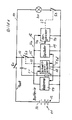
- An incandescent lamp h1 is located in an incandescent lamp circuit 10, which is supplied with energy by a battery 11.
- the incandescent lamp circuit 10 there is a first switch S1 in front of the incandescent lamp h1;
- a connecting terminal 12 of a second switch S2 is connected between the first switch S1 and the incandescent lamp, and a third switch S3 is connected in the incandescent lamp circuit 10 behind the incandescent lamp h1.
- a leg of a differentiating element is connected, which is formed from a capacitor C and a resistor R. becomes; the other leg of the differentiator is connected to the negative pole 13 of the battery.
- the positive pole of the battery has the reference number 14.
- the other terminal 15 of the switch is connected to a line 16 which is connected to a reference circuit 17; the circuit arrangement also has a threshold switch 18, an oscillator 19 and a comparator circuit 20.
- the threshold switch 18 Via the differentiator R / C, the threshold switch 18 is given a voltage pulse via a line 21 connected between the capacitor C and the resistor R. As a result, the threshold switch 18 closes the electronic switch S2 via the line 22 shown in broken lines.
- the line voltage 16 indicates the battery voltage U h .
- the threshold switch compares the voltage output by the reference circuit 17 with the battery voltage U h , and then if U h is greater than the reference voltage U Ref , the threshold switch gives the "on" signal to the switch S2 via the line 22, which then closes remains.
- the circuit thus supplies itself (self-holding circuit).
- the oscillator 19 generates a triangular voltage U D which , controlled by the reference voltage U Ref, has a maximum amplitude value U Ref + U D and an amplitude lowest value U Ref - U D Has.
- the triangle voltage U D is compared by the comparator with the battery voltage U h . Is U h > U Ref + U D then the electronic switch S3 is continuously switched on via the further dash-dotted line 23 and the incandescent lamp H1 burns.
- the threshold will be reached if the voltage falls below the threshold U Ref + U D the switch S3 no longer turned on, but periodically with a clock ratio that corresponds to the instantaneous value of the battery voltage.
- the mean voltage value on the lamp H 1 is reduced; the luminous flux decreases.
- the luminous flux can decrease to such an extent that when the deep discharge protection limit value is reached it is only a few percent of the nominal luminous flux.
- the deep discharge protection is formed from the interaction of the reference circuit arrangement, the threshold switch and the switch S2.
- the threshold switch responds and opens the switch S2, so that the voltage U h disappears and the battery current goes to a few milliamps towards zero, since the lamp h1 goes out and is not switched on again .
- the switch S 1 is closed. Characterized flows over the differentiator, which consists of a series connection of resistors R1, R2, a diode V2 and a capacitor C1 and is connected in parallel to the series connection of battery 11 and the switch S1, a short time a current.
- the base of a transistor V1 is connected between the two resistors R1 and R2, and the voltage drop across the resistor R1 drives the base of the transistor V1, so that it goes into the conductive state.
- the voltage U h is applied to line 16.
- Parallel to the resistor R6 and the diode V6 is a voltage divider consisting of two resistors R5 and R9; in a comparator V5 the voltage divided by the two resistors R5 and R9 is compared with the reference voltage U Ref ; the minus input lies between the resistor R6 and the diode V6.
- the output of the comparator is connected to the base of a transistor V4 and between the collector of transistor V1 and the base of transistor V4 is a resistor R lamb.
- the transistor V4 is controlled by the comparator V5 in the conductive state and resistors R1, R2 and diode V2, the transistor V1 remains conductive; the circuit supplies itself (self-holding circuit).
- the oscillator circuit is formed from a resistor R10, one leg of which is connected between the Zener diode and the resistor R6, a resistor R11 which is in series with the resistor R10, a resistor R7 which is in series with the resistor R11 and whose another leg is connected to line 16, a resistor R12, which is connected in parallel to the minus input and the output of a comparator V5 ⁇ , the positive input of which is connected between the resistors R10 and R11 and whose output is also between the resistors R7 and R11 is switched on and a capacitance C3, which lies between the negative input of the comparator V5 ⁇ and the negative pole of the battery.
- the resistance R12 is with one leg between the minus connection of the comparator V5 ⁇ and the capacitance C3 and with the other leg at the output of the comparator V5 ⁇ .
- This oscillator circuit generates a triangular voltage U D of a capacitance which is the maximum value of and a lowest of owns.
- the frequency of the oscillator is determined by the resistors R12, R10, R11 and R7 and the capacitance C3 and is due to the appropriate dimensioning of these parts between 100 and 500 Hertz.
- This delta voltage U D is fed to the positive input of a further comparator V5 ⁇ ; the negative connection of the comparator V5 ⁇ is at the center tap of a potentiometer R13, which is connected via further resistors R8 and R14 on the one hand to the line U h and on the other hand to the negative pole of the battery.
- This triangular voltage U D is compared by the comparator V5 ⁇ via the voltage divider R8, R13, R14 with the voltage U h .
- the voltage divider is applied to the output of the comparator V5 ⁇ be resistors R15 and R16 driven the base of a transistor V7, so that the transistor V7, whose emitter is connected to line 16, conductive and via a voltage divider in the collector circuit from the resistors R17 and R18 and the switching transistor V8 continuously conductive; the base of the transistor is connected to the collector V7 via the resistor R16.
- Parallel to the base-emitter path of the transistor V8 is the resistor R18.
- a capacitance C4 lies parallel to the basic collector path. If the transistor V8 is conductive, the light bulb h1 burns.
- the comparator V5 switches to zero and the transistor V4 blocks; thus the transistor V1 is driven into the blocking state via the diode V2, the resistor and the resistor R2.
- the circuit thereby takes the supply voltage U h , whereby the deep discharge protection with reclosing lock is generated.
- the entire circuit can only be reactivated by opening and reclosing the switch S 1.
- the lamp is switched on continuously. If the cell voltage drops during the discharge, e.g. a nickel-cadmium battery to a value of less than 1 volt / cell, the luminous flux of the incandescent lamp is reduced disproportionately. This shows the user that the battery capacity is at an end. By reducing the lamp current, the remaining capacity is used to extend the burning time. Shortly before the deep discharge protection responds, the luminous flux has such small values that the user may turns itself off.
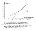
- Figure 3 When drawn out, the luminous flux of a 4.8 volt, 5 watt incandescent lamp can be seen depending on the battery voltage. The dotted line runs exactly on the solid line up to a battery voltage of 3.9 volts. If the battery voltage drops further, i.e. So decrease in capacity, the current through the consumer drops disproportionately due to the circuit arrangement according to the invention up to the value of 3.6 volts battery voltage. At this voltage, the deep discharge protection responds and disconnects the lamp h1 from the battery.
Landscapes
- Engineering & Computer Science (AREA)
- Power Engineering (AREA)
- Physics & Mathematics (AREA)
- General Physics & Mathematics (AREA)
- Circuit Arrangement For Electric Light Sources In General (AREA)
- Secondary Cells (AREA)
- Charge And Discharge Circuits For Batteries Or The Like (AREA)
Applications Claiming Priority (2)
| Application Number | Priority Date | Filing Date | Title |
|---|---|---|---|
| DE3611484A DE3611484C2 (de) | 1986-04-05 | 1986-04-05 | Schaltungsanordnung für eine tragbare Leuchte |
| DE3611484 | 1986-04-05 |
Publications (2)
| Publication Number | Publication Date |
|---|---|
| EP0240883A2 true EP0240883A2 (fr) | 1987-10-14 |
| EP0240883A3 EP0240883A3 (fr) | 1989-12-20 |
Family
ID=6298035
Family Applications (1)
| Application Number | Title | Priority Date | Filing Date |
|---|---|---|---|
| EP87104644A Ceased EP0240883A3 (fr) | 1986-04-05 | 1987-03-28 | Procédé d'obtention d'une protection de décharge profonde pour une batterie rechargeable et circuit pour la réalisation du procédé |
Country Status (2)
| Country | Link |
|---|---|
| EP (1) | EP0240883A3 (fr) |
| DE (1) | DE3611484C2 (fr) |
Cited By (14)
| Publication number | Priority date | Publication date | Assignee | Title |
|---|---|---|---|---|
| AU627101B2 (en) * | 1990-07-19 | 1992-08-13 | Samsung Electronics Co., Ltd. | An overdischarge and overvoltage protection circuit for a battery in a portable and mobile communication system |
| WO1993006643A1 (fr) * | 1991-09-26 | 1993-04-01 | Braun Aktiengesellschaft | Appareil a pile |
| US5694020A (en) * | 1991-09-26 | 1997-12-02 | Braun Aktiengesellschaft | Apparatus for controlling battery discharge |
| US6188142B1 (en) | 1996-09-14 | 2001-02-13 | Braun Gmbh | Method and arrangement for disconnecting consumers |
| WO2001089056A1 (fr) * | 2000-05-19 | 2001-11-22 | Infineon Technologies Ag | Circuit pour proteger une batterie de decharges totales |
| US6571091B1 (en) | 1995-05-30 | 2003-05-27 | Motorola, Inc. | Power control method and apparatus suitable for use in a radio communication device |
| WO2006037978A1 (fr) * | 2004-10-06 | 2006-04-13 | Zi Medical Plc | Dispositif utilisant l'energie residuelle d'une batterie |
| US7342381B2 (en) | 2002-11-22 | 2008-03-11 | Milwaukee Electric Tool Corporation | Method and system for battery protection employing sampling of measurements |
| GB2429344B (en) * | 2004-05-24 | 2008-12-31 | Milwaukee Electric Tool Corp | Method and system for battery protection |
| US7589500B2 (en) | 2002-11-22 | 2009-09-15 | Milwaukee Electric Tool Corporation | Method and system for battery protection |
| US7720601B2 (en) | 2000-02-15 | 2010-05-18 | Motorola, Inc. | Method and apparatus for compressing GPS satellite broadcast message information |
| EP1993185A3 (fr) * | 2007-05-16 | 2012-08-29 | Hitachi Vehicle Energy, Ltd. | Contrôleur de cellules, module de batterie et système d'alimentation électrique |
| CN105790375A (zh) * | 2016-04-25 | 2016-07-20 | 六安市同心畅能电子科技有限公司 | 5v电源适配器智能控制电路 |
| US9680325B2 (en) | 2002-11-22 | 2017-06-13 | Milwaukee Electric Tool Corporation | Lithium-based battery pack for a hand held power tool |
Families Citing this family (17)
| Publication number | Priority date | Publication date | Assignee | Title |
|---|---|---|---|---|
| DE3841769C1 (en) * | 1988-12-12 | 1990-06-07 | Juergen 8014 Neubiberg De Wemhoener | Circuit for ensuring the provision of starting energy in motor vehicles with internal combustion engines |
| DE3929185A1 (de) * | 1989-09-02 | 1990-03-29 | Claus Dr Wuensche | Verfahren zur verhinderung der umpolspannung bei akkumulatorzellen, insbesondere bei nicd-zellen |
| JPH04331425A (ja) * | 1991-04-26 | 1992-11-19 | Sony Corp | 過充電防止装置、過放電防止装置、過充電・過放電防止装置、プリント基板並びにバッテリーパック |
| US5547775A (en) * | 1991-04-26 | 1996-08-20 | Sony Corporation | Circuit for preventing overcharge and overdischarge of secondary batteries |
| JP3136677B2 (ja) * | 1991-07-31 | 2001-02-19 | ソニー株式会社 | 2次電池の過充電及び過放電防止回路 |
| SE500486C2 (sv) * | 1991-10-03 | 1994-07-04 | Alfa Laval Agri Int | Sätt att anpassa driften av en elstängselapparat till batterityp |
| DE4234231A1 (de) * | 1992-10-10 | 1994-04-14 | Adolf Wuerth Gmbh & Co Kg | Wiederaufladbarer Akku |
| DE4241066C1 (de) * | 1992-12-05 | 1994-01-13 | Braun Ag | Automatische Laststromrückregelung |
| DE9302801U1 (de) | 1993-02-26 | 1993-12-09 | Helix Solarelektronik GmbH, 89081 Ulm | Vorrichtung zum Schutz von Akkumulatoren vor zu tiefer Entladung mit variabler Entladeendspannung |
| JP3222999B2 (ja) * | 1993-08-20 | 2001-10-29 | 三洋電機株式会社 | 二次電池の過放電防止回路 |
| US5581170A (en) | 1994-12-12 | 1996-12-03 | Unitrode Corporation | Battery protector |
| US5652501A (en) | 1994-12-12 | 1997-07-29 | Unitrode Corporation | Voltage sensor for detecting cell voltages |
| JPH08172722A (ja) * | 1994-12-19 | 1996-07-02 | Yamaha Motor Co Ltd | 過電流取出防止装置 |
| DE29607780U1 (de) * | 1996-04-30 | 1996-06-13 | Trautmann KG Calira-Apparatebau, 87600 Kaufbeuren | Schaltung zum Schutz einer Batterie vor Tiefentladung |
| JP3380766B2 (ja) * | 1999-03-18 | 2003-02-24 | 富士通株式会社 | 保護方法及び制御回路並びに電池ユニット |
| DE10333418B4 (de) * | 2003-07-17 | 2005-11-17 | Witte & Sutor Gmbh | LED-Taschenleuchte |
| DE102005026998A1 (de) * | 2005-06-10 | 2006-12-14 | Siemens Ag | Anordnung mit einem Registriergerät |
Family Cites Families (6)
| Publication number | Priority date | Publication date | Assignee | Title |
|---|---|---|---|---|
| US3519842A (en) * | 1964-12-17 | 1970-07-07 | Matsushita Electric Industrial Co Ltd | Voltage switching device |
| DE2128015B1 (de) * | 1971-06-05 | 1972-10-05 | Friemann & Wolf Gmbh | Schaltungsanordnung zum Schutz vor Tiefentladung eines Akkumulators in einem von einem Ladegerät aufladbaren Notstromversorgungsgerät |
| US3969635A (en) * | 1974-02-25 | 1976-07-13 | Wilke William G | Voltage condition monitor |
| DE2433356A1 (de) * | 1974-07-11 | 1976-01-22 | Ehmann Elektrotech | Anordnung zur stromversorgung von elektrischen verbrauchern aus einer batterie |
| US3932797A (en) * | 1974-12-24 | 1976-01-13 | Flight Systems, Inc. | Self-testing battery discharge indicator |
| US4342953A (en) * | 1980-05-02 | 1982-08-03 | Nicholl Brothers, Inc. | Battery protection circuit |
-
1986
- 1986-04-05 DE DE3611484A patent/DE3611484C2/de not_active Expired - Lifetime
-
1987
- 1987-03-28 EP EP87104644A patent/EP0240883A3/fr not_active Ceased
Cited By (31)
| Publication number | Priority date | Publication date | Assignee | Title |
|---|---|---|---|---|
| AU627101B2 (en) * | 1990-07-19 | 1992-08-13 | Samsung Electronics Co., Ltd. | An overdischarge and overvoltage protection circuit for a battery in a portable and mobile communication system |
| WO1993006643A1 (fr) * | 1991-09-26 | 1993-04-01 | Braun Aktiengesellschaft | Appareil a pile |
| EP0712007A3 (fr) * | 1991-09-26 | 1996-07-24 | Braun Ag | Rasoir électrique ou tondeuse capillaire fonctionnant sur pile |
| US5694020A (en) * | 1991-09-26 | 1997-12-02 | Braun Aktiengesellschaft | Apparatus for controlling battery discharge |
| US6571091B1 (en) | 1995-05-30 | 2003-05-27 | Motorola, Inc. | Power control method and apparatus suitable for use in a radio communication device |
| US6188142B1 (en) | 1996-09-14 | 2001-02-13 | Braun Gmbh | Method and arrangement for disconnecting consumers |
| US7720601B2 (en) | 2000-02-15 | 2010-05-18 | Motorola, Inc. | Method and apparatus for compressing GPS satellite broadcast message information |
| WO2001089056A1 (fr) * | 2000-05-19 | 2001-11-22 | Infineon Technologies Ag | Circuit pour proteger une batterie de decharges totales |
| US7006340B2 (en) | 2000-05-19 | 2006-02-28 | Infineon Technologies Ag | Circuit configuration for protecting a battery against deep discharge |
| US7667437B2 (en) | 2002-11-22 | 2010-02-23 | Milwaukee Electric Tool Corporation | Method and system for protection of a lithium-based multicell battery pack including a heat sink |
| US11196080B2 (en) | 2002-11-22 | 2021-12-07 | Milwaukee Electric Tool Corporation | Method and system for battery protection |
| US7492124B2 (en) | 2002-11-22 | 2009-02-17 | Milwaukee Electric Tool Corporation | Method and system for battery protection |
| US7504804B2 (en) | 2002-11-22 | 2009-03-17 | Milwaukee Electric Tool Corporation | Method and system for protection of a lithium-based multicell battery pack including a heat sink |
| US7589500B2 (en) | 2002-11-22 | 2009-09-15 | Milwaukee Electric Tool Corporation | Method and system for battery protection |
| US7342381B2 (en) | 2002-11-22 | 2008-03-11 | Milwaukee Electric Tool Corporation | Method and system for battery protection employing sampling of measurements |
| US10593991B2 (en) | 2002-11-22 | 2020-03-17 | Milwaukee Electric Tool Corporation | Method and system for battery protection |
| US7952326B2 (en) | 2002-11-22 | 2011-05-31 | Milwaukee Electric Tool Corporation | Method and system for battery protection employing over-discharge control |
| US11469608B2 (en) | 2002-11-22 | 2022-10-11 | Milwaukee Electric Tool Corporation | Lithium-based battery pack for a hand held power tool |
| US10536022B2 (en) | 2002-11-22 | 2020-01-14 | Milwaukee Electric Tool Corporation | Lithium-based battery pack for a hand held power tool |
| US10862327B2 (en) | 2002-11-22 | 2020-12-08 | Milwaukee Electric Tool Corporation | Lithium-based battery pack for a hand held power tool |
| US9660293B2 (en) | 2002-11-22 | 2017-05-23 | Milwaukee Electric Tool Corporation | Method and system for battery protection |
| US9680325B2 (en) | 2002-11-22 | 2017-06-13 | Milwaukee Electric Tool Corporation | Lithium-based battery pack for a hand held power tool |
| US9819051B2 (en) | 2002-11-22 | 2017-11-14 | Milwaukee Electric Tool Corporation | Method and system for battery protection |
| US10097026B2 (en) | 2002-11-22 | 2018-10-09 | Milwaukee Electric Tool Corporation | Lithium-based battery pack for a hand held power tool |
| US10224566B2 (en) | 2002-11-22 | 2019-03-05 | Milwaukee Electric Tool Corporation | Method and system for battery protection |
| GB2429344B (en) * | 2004-05-24 | 2008-12-31 | Milwaukee Electric Tool Corp | Method and system for battery protection |
| WO2006037978A1 (fr) * | 2004-10-06 | 2006-04-13 | Zi Medical Plc | Dispositif utilisant l'energie residuelle d'une batterie |
| US9048667B2 (en) | 2007-05-16 | 2015-06-02 | Hitachi Automotive Systems, Ltd. | Cell controller, battery module and power supply system |
| EP1993185A3 (fr) * | 2007-05-16 | 2012-08-29 | Hitachi Vehicle Energy, Ltd. | Contrôleur de cellules, module de batterie et système d'alimentation électrique |
| CN105790375B (zh) * | 2016-04-25 | 2019-04-02 | 六安市同心畅能电子科技有限公司 | 5v电源适配器智能控制电路 |
| CN105790375A (zh) * | 2016-04-25 | 2016-07-20 | 六安市同心畅能电子科技有限公司 | 5v电源适配器智能控制电路 |
Also Published As
| Publication number | Publication date |
|---|---|
| DE3611484A1 (de) | 1987-10-08 |
| DE3611484C2 (de) | 1994-06-09 |
| EP0240883A3 (fr) | 1989-12-20 |
Similar Documents
| Publication | Publication Date | Title |
|---|---|---|
| DE3611484A1 (de) | Verfahren zur erzielung eines tiefentladeschutzes fuer eine wiederaufladbare batterie, und schaltungsanordnung zur durchfuehrung des verfahrens | |
| DE3888303T2 (de) | Über-Entladungsschutzschaltung. | |
| DE69508746T2 (de) | Selbstkonfigurierendes Batterieladegerät mit Mehrfachfunktionen als Versorgungsspannungsregler für batteriebetriebene Geräte | |
| DE2124579A1 (de) | Schaltung zum automatischen Aufladen einer Batterie | |
| EP1233657B1 (fr) | Circuit de protection pour tube fluorescent | |
| DE4302201A1 (de) | Batterieladegerät und Verfahren zum Aufladen von Akkumulatoren | |
| EP0637118B1 (fr) | Circuit pour limiter le courant de démarrage et surtension d'un ballast électronique | |
| DE3639116A1 (de) | Gleichspannungsversorgungsschaltung fuer leuchtstofflampen | |
| DE19622803A1 (de) | Lichtstromkreis für Entladungslampe | |
| DE1438857B2 (de) | Gerät zum Laden von Akkumulatoren | |
| DE3227522C2 (de) | Verfahren und Vorrichtung zum Schnelladen von Nickelcadmium-Akkumulatoren und gleichzeitigem Überwachen der eingeladenen Gesamtkapazität | |
| EP0030276B1 (fr) | Agencement de circuit pour la charge d'une batterie | |
| DE3322943C2 (fr) | ||
| DE2364186A1 (de) | Selbsttaetige ladeeinrichtung fuer elektrische batterien | |
| EP0339598A2 (fr) | Circuit de protection pour charges inductives | |
| DE2929818A1 (de) | Regelschaltung fuer ein netzgeraet | |
| DE4309974A1 (de) | Stromversorgungsschaltung | |
| EP0021266B1 (fr) | Dispositif d'éclairage électrique pour bicyclettes | |
| DE1638087B2 (de) | Stromversorgungseinrichtung mit einem Generator und einem Akkumulator | |
| DE2733594C3 (de) | Schaltungsanordnung zum Laden einer wiederaufladbaren Batterie | |
| DE2438149C3 (de) | Schaltungsanordnung zum Schutz elektrischer Akkumulatoren vor Tiefentladung | |
| DE1935201A1 (de) | Verfahren und Vorrichtung zum Schnelladen von Batterien | |
| DE3502826A1 (de) | Solarstrom-anlage | |
| DE3138512C2 (fr) | ||
| DE1046737B (de) | Einrichtung zur selbsttaetigen Ladung bzw. Spannungskonstanthaltung einer elektrischen Batterie |
Legal Events
| Date | Code | Title | Description |
|---|---|---|---|
| PUAI | Public reference made under article 153(3) epc to a published international application that has entered the european phase |
Free format text: ORIGINAL CODE: 0009012 |
|
| AK | Designated contracting states |
Kind code of ref document: A2 Designated state(s): DE FR GB IT |
|
| RAP1 | Party data changed (applicant data changed or rights of an application transferred) |
Owner name: ABB CEAG LICHT- UND STROMVERSORGUNGSTECHNIK GMBH |
|
| PUAL | Search report despatched |
Free format text: ORIGINAL CODE: 0009013 |
|
| AK | Designated contracting states |
Kind code of ref document: A3 Designated state(s): DE FR GB IT |
|
| 17P | Request for examination filed |
Effective date: 19900511 |
|
| 17Q | First examination report despatched |
Effective date: 19911218 |
|
| STAA | Information on the status of an ep patent application or granted ep patent |
Free format text: STATUS: THE APPLICATION HAS BEEN REFUSED |
|
| 18R | Application refused |
Effective date: 19921005 |
|
| RIN1 | Information on inventor provided before grant (corrected) |
Inventor name: JUETTE, REINHOLD |