EP0240957A2 - Dispositif de revêtement de pièces métalliques ou non métalliques - Google Patents
Dispositif de revêtement de pièces métalliques ou non métalliques Download PDFInfo
- Publication number
- EP0240957A2 EP0240957A2 EP87105010A EP87105010A EP0240957A2 EP 0240957 A2 EP0240957 A2 EP 0240957A2 EP 87105010 A EP87105010 A EP 87105010A EP 87105010 A EP87105010 A EP 87105010A EP 0240957 A2 EP0240957 A2 EP 0240957A2
- Authority
- EP
- European Patent Office
- Prior art keywords
- container
- workpiece
- electrolyte
- metallic
- anode
- Prior art date
- Legal status (The legal status is an assumption and is not a legal conclusion. Google has not performed a legal analysis and makes no representation as to the accuracy of the status listed.)
- Withdrawn
Links
Images
Classifications
-
- C—CHEMISTRY; METALLURGY
- C25—ELECTROLYTIC OR ELECTROPHORETIC PROCESSES; APPARATUS THEREFOR
- C25D—PROCESSES FOR THE ELECTROLYTIC OR ELECTROPHORETIC PRODUCTION OF COATINGS; ELECTROFORMING; APPARATUS THEREFOR
- C25D5/00—Electroplating characterised by the process; Pretreatment or after-treatment of workpieces
- C25D5/02—Electroplating of selected surface areas
Definitions
- the invention relates to a device for the surface coating of metallic or non-metallic workpieces with process solutions containing ions, in particular electroplating with an electrolyte is tightly pressed, and the container has an anode in its interior, while the workpiece and in particular its surface in contact with the electrolyte forms the cathode.
- the surface of the workpiece delimited by the opening of the container can be galvanically processed and thereby provided with a coating.
- the coating takes place essentially over the entire surface that is covered by the opening of the container. After-treatment of small damaged areas of the surface coating is therefore carried out in addition to filling the damaged surface coating also a relatively large-area metal application on the adjacent, undamaged surface areas of the workpiece, so that extensive post-processing by removing the excess thickness of the coating is required.
- the invention has for its object to provide a device of the type described above, with which parts of the surface of a workpiece can be provided with a metallic surface layer and, in particular, damaged areas of a metallic surface coating can be reworked, the metal application in particular at predetermined locations within that of the Opening of the container covered surface of the workpiece takes place.
- the anode provided in the interior of the container with a spherical configuration of its end face or the like to form a smooth-walled depression by grinding.
- the end face of the anode is due to its dimensions and the spherical design in shape and size of the to a smooth-walled trough by grinding or the like.
- Elaborated, damaged area adjusted so that the streamline distribution is precisely aligned.
- This predetermined streamline distribution ensures that the like to a smooth-walled trough by grinding. worked out, damaged area is filled in, while on the neighboring parts of the surface of the workpiece there is little or almost no metal application. After finishing the surface coating on the damaged area, only slight excess thicknesses of the coating have to be removed.
- the device is used for surface coating, such as electroplating, in particular after-treatment of damaged surfaces of metallic or non-metallic workpieces with process solutions containing ions, such as an electrolyte.
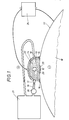
- a metallic roller 10 which is provided with a metallic surface coating 11, is aftertreated, since the surface coating 11 has a damaged area.
- the aftertreatment is carried out galvanically with an electrolyte 13.
- the roller 10 to be treated is pressed tightly against a container receiving the electrolyte 13 with a peripheral edge 15 of an opening allowing the electrolyte 13 to be treated on the surface of the roller 10 to be treated.
- the pressing of the container 14 against the roller 10 can or the like in a known manner with a bandage. take place and is not shown for the sake of simplicity.
- the peripheral edge 15 of the container opening is pressed against the surface of the workpiece 10 with a seal 16 made of flexible material such as rubber, plastic or the like, so that the electrolyte 13 is secured against leakage.
- the container 14 to be pressed against the surface of the roller 10 and holding the electrolyte 13 consists of a material which is resistant to the electrolyte 13, such as titanium, plastic or the like.
- the container 14 is provided with an inlet opening 17 and an outlet opening 18 so that the electrolyte can flow in a circuit through the container 14.
- a pump 20 is provided in the inlet pipe 19.
- the electrolyte 13 flowing through the container 14 comes from a storage container 21 and flows back to the latter.
- the gases generated during electroplating also reach the storage container and can escape from it.
- the container 14 can be made relatively small in a simple manner, and a sufficient amount of electrolyte is nevertheless available, since the electrolyte comes from a relatively large storage container 21 and flows back to the latter.
- the container 14 can thus also for repairs in difficult to access places of devices, equipment or the like. be used because it takes up little space.
- the electrolyte can also be refreshed and / or heated in the storage container 21.
- the heated electrolyte can also be used to heat the workpiece 10 to be treated, in particular at the damaged area 12.
- an anode 23 is arranged in the interior 22 of the container 14, while the roller 10 and in particular its surface in contact with the electrolyte 13 forms the cathode.
- Anode 23 and the roller 10, which acts as cathode, are connected to a power generator 24.
- the damaged area 12 becomes a smooth-walled depression 25 by grinding or the like. to work out.
- the anode 23 provided in the interior 22 of the container 14 is adapted with a spherical configuration on the end face of the trough 25 facing the damaged area 12. This spherical, in particular spherical design of the anode results in a streamline distribution adapted to the trough 25.
- the anode 23 is essentially perpendicular to the damaged area 12.
- the embodiment shown is merely an example of realizing the invention and it is not restricted thereto. Rather, many other designs and applications are possible.
- the housing 14 could also be used to flow a cleaning liquid to clean and degrease the damaged area before treatment.
- the like at the damaged point by grinding or the like. be worked out, smooth-walled trough in their shape and size of the shape and size of the anode are adapted.
Landscapes
- Chemical & Material Sciences (AREA)
- Engineering & Computer Science (AREA)
- Chemical Kinetics & Catalysis (AREA)
- Electrochemistry (AREA)
- Materials Engineering (AREA)
- Metallurgy (AREA)
- Organic Chemistry (AREA)
- Electroplating Methods And Accessories (AREA)
Applications Claiming Priority (2)
| Application Number | Priority Date | Filing Date | Title |
|---|---|---|---|
| DE19863611833 DE3611833A1 (de) | 1986-04-08 | 1986-04-08 | Vorrichtung zur oberflaechenbeschichtung, insbesondere nachbehandlung beschaedigter oberflaechen von metallischen oder nichtmetallischen werkstuecken |
| DE3611833 | 1986-04-08 |
Publications (2)
| Publication Number | Publication Date |
|---|---|
| EP0240957A2 true EP0240957A2 (fr) | 1987-10-14 |
| EP0240957A3 EP0240957A3 (fr) | 1987-11-11 |
Family
ID=6298247
Family Applications (1)
| Application Number | Title | Priority Date | Filing Date |
|---|---|---|---|
| EP87105010A Withdrawn EP0240957A3 (fr) | 1986-04-08 | 1987-04-04 | Dispositif de revêtement de pièces métalliques ou non métalliques |
Country Status (3)
| Country | Link |
|---|---|
| EP (1) | EP0240957A3 (fr) |
| JP (1) | JPS62247096A (fr) |
| DE (1) | DE3611833A1 (fr) |
Cited By (2)
| Publication number | Priority date | Publication date | Assignee | Title |
|---|---|---|---|---|
| WO1997023331A1 (fr) * | 1995-12-22 | 1997-07-03 | Hueck Engraving Gmbh | Procede et dispositif de reparation et/ou de retouche de petits dommages superficiels d'un plateau de pression ou d'une bande sans fin d'impression de structure dans la couche superficielle de panneaux en bois ou stratifies enduits de plastique |
| WO2007124728A2 (fr) | 2006-05-02 | 2007-11-08 | Mahle International Gmbh | Masque pour la finition galvanique de la surface extérieure d'un corps constitué d'un matériau électriquement conducteur et procédé de fabrication du masque |
Families Citing this family (2)
| Publication number | Priority date | Publication date | Assignee | Title |
|---|---|---|---|---|
| DE3736240A1 (de) * | 1987-10-27 | 1989-05-11 | Flachglas Ag | Vorrichtung zur galvanischen verstaerkung einer leiterspur auf einer glasscheibe |
| CN107532323B (zh) * | 2015-05-08 | 2019-07-12 | 株式会社日立制作所 | 湿式表面处理装置 |
Family Cites Families (4)
| Publication number | Priority date | Publication date | Assignee | Title |
|---|---|---|---|---|
| US1771680A (en) * | 1927-03-29 | 1930-07-29 | Ishisaka Sansaku | Apparatus for electroplating |
| GB566776A (en) * | 1943-06-09 | 1945-01-12 | Maurice Stuart Lane | Improvements in or relating to electroplating |
| CH613880A5 (fr) * | 1975-09-29 | 1979-10-31 | Emile Steiger | |
| BE899632A (nl) * | 1984-05-11 | 1984-11-12 | Ebes Ver Energie Schelde | Werkwijze om pijpen van een stoomgenerator te herstellen. |
-
1986
- 1986-04-08 DE DE19863611833 patent/DE3611833A1/de active Granted
-
1987
- 1987-04-04 EP EP87105010A patent/EP0240957A3/fr not_active Withdrawn
- 1987-04-07 JP JP8392987A patent/JPS62247096A/ja active Pending
Cited By (3)
| Publication number | Priority date | Publication date | Assignee | Title |
|---|---|---|---|---|
| WO1997023331A1 (fr) * | 1995-12-22 | 1997-07-03 | Hueck Engraving Gmbh | Procede et dispositif de reparation et/ou de retouche de petits dommages superficiels d'un plateau de pression ou d'une bande sans fin d'impression de structure dans la couche superficielle de panneaux en bois ou stratifies enduits de plastique |
| WO2007124728A2 (fr) | 2006-05-02 | 2007-11-08 | Mahle International Gmbh | Masque pour la finition galvanique de la surface extérieure d'un corps constitué d'un matériau électriquement conducteur et procédé de fabrication du masque |
| WO2007124728A3 (fr) * | 2006-05-02 | 2009-01-22 | Mahle Int Gmbh | Masque pour la finition galvanique de la surface extérieure d'un corps constitué d'un matériau électriquement conducteur et procédé de fabrication du masque |
Also Published As
| Publication number | Publication date |
|---|---|
| DE3611833A1 (de) | 1987-10-15 |
| EP0240957A3 (fr) | 1987-11-11 |
| JPS62247096A (ja) | 1987-10-28 |
| DE3611833C2 (fr) | 1988-02-18 |
Similar Documents
| Publication | Publication Date | Title |
|---|---|---|
| DE69402952T2 (de) | Vorrichtung zu einer insbesonderen selektiven elektrochemischen Behandlung eines leitenden Substrats | |
| EP0393540B1 (fr) | Procédé de revêtement galvanique de segments de surface, qui sont situés sur la surface d'un objet et outil fabriqué selon ce procédé, en particulier meule de rectification | |
| EP0146833B1 (fr) | Dispositif pour le polissage électrolytique des surfaces intérieures d'objets cylindriques creux | |
| DE202008011646U1 (de) | Einrichtung zum Plasmapolieren unter Verwendung eines flüssigen Elektrolyten | |
| DE3611833C2 (fr) | ||
| DE1540736B1 (de) | Vorrichtung zur automatischen elektrochemischabtr enden bearbeitung von werkstuecken | |
| DE60128427T2 (de) | Verfahren und Einrichtungen zur elekrochemischen Behandlung eines Artikels | |
| EP0874921B1 (fr) | Procede et installation de traitement electrochimique d'objets longilignes | |
| DE2937747A1 (de) | Verfahren und einrichtung zum elektrochemischen polieren von metallteilen | |
| EP2047012B1 (fr) | Procédé de traitement de la surface d'une piece | |
| DE2855041C2 (de) | Verfahren und Vorrichtung zum automatischen Nacharbeiten von Schweißelektroden | |
| DE69403871T2 (de) | Vorrichtung zur Behandlung von Oberflächen | |
| DE3810175A1 (de) | Kathodenzerstaeubungsvorrichtung | |
| DE69906733T2 (de) | Verfahren und vorrichtung zur elektroplattierung | |
| DE1172512B (de) | Haltevorrichtung fuer perforierte Tauch-trommeln bei Anlagen zur Oberflaechen-behandlung von Massenteilen in Fluessigkeiten | |
| DE2121110C3 (de) | Vorrichtung zum elektrochemischen Entgraten | |
| DE3708779C2 (fr) | ||
| DE3903696A1 (de) | Vorrichtung zum auf- und/oder abtragen von ueberzuegen bei werkstuecken | |
| DE19822196A1 (de) | Verfahren zur selektiven, bereichsweisen Beschichtung metallischer Bauteile und Vorrichtung zur Durchführung des Verfahrens | |
| DE3317034C2 (de) | Vorrichtung zum Schneiden und Konturbearbeiten von metallischen Werkstücken nach dem ECM-Verfahren | |
| DD230138A3 (de) | Verfahren zur chemischen und elektrochemischen metallabscheidung | |
| DE1217171B (de) | Verfahren und Vorrichtung zur massgenauen Bearbeitung der Aussen- und/oder Innenflaeche von rohrfoermigen Koerpern | |
| DD231752A1 (de) | Verfahren und werkzeugkatode zum elektrochemischen entgraten und runden von metallkanten | |
| WO2001038030A1 (fr) | Procede d'usinage electrochimique de pieces | |
| DE2125837A1 (de) | Vorrichtung zum Galvanisieren ausgewählter Oberflächenteile elektrisch leitender Werkstücke |
Legal Events
| Date | Code | Title | Description |
|---|---|---|---|
| PUAI | Public reference made under article 153(3) epc to a published international application that has entered the european phase |
Free format text: ORIGINAL CODE: 0009012 |
|
| PUAL | Search report despatched |
Free format text: ORIGINAL CODE: 0009013 |
|
| AK | Designated contracting states |
Kind code of ref document: A2 Designated state(s): AT BE CH ES FR GB GR IT LI LU NL SE |
|
| AK | Designated contracting states |
Kind code of ref document: A3 Designated state(s): AT BE CH ES FR GB GR IT LI LU NL SE |
|
| STAA | Information on the status of an ep patent application or granted ep patent |
Free format text: STATUS: THE APPLICATION IS DEEMED TO BE WITHDRAWN |
|
| 18D | Application deemed to be withdrawn |
Effective date: 19880512 |
|
| RIN1 | Information on inventor provided before grant (corrected) |
Inventor name: HOFFMANN, REINHOLD, DR. DIPL.-CHEM. |