EP0241123A1 - Appareil à soupape pour un système de traitement d'un patient par photoactivation - Google Patents
Appareil à soupape pour un système de traitement d'un patient par photoactivation Download PDFInfo
- Publication number
- EP0241123A1 EP0241123A1 EP87301722A EP87301722A EP0241123A1 EP 0241123 A1 EP0241123 A1 EP 0241123A1 EP 87301722 A EP87301722 A EP 87301722A EP 87301722 A EP87301722 A EP 87301722A EP 0241123 A1 EP0241123 A1 EP 0241123A1
- Authority
- EP
- European Patent Office
- Prior art keywords
- locking element
- blood
- clamping means
- container
- clamping
- Prior art date
- Legal status (The legal status is an assumption and is not a legal conclusion. Google has not performed a legal analysis and makes no representation as to the accuracy of the status listed.)
- Granted
Links
Images



Classifications
-
- A—HUMAN NECESSITIES
- A61—MEDICAL OR VETERINARY SCIENCE; HYGIENE
- A61M—DEVICES FOR INTRODUCING MEDIA INTO, OR ONTO, THE BODY; DEVICES FOR TRANSDUCING BODY MEDIA OR FOR TAKING MEDIA FROM THE BODY; DEVICES FOR PRODUCING OR ENDING SLEEP OR STUPOR
- A61M39/00—Tubes, tube connectors, tube couplings, valves, access sites or the like, specially adapted for medical use
- A61M39/22—Valves or arrangement of valves
- A61M39/28—Clamping means for squeezing flexible tubes, e.g. roller clamps
Definitions
- This invention relates to the field of treating cells with photoactivatable compounds and radiation which activates the compound thereby affecting the cells and specifically, relates to clinically useful systems for the extracorporeal treatment of blood cells, especially leukocytes, with UV radiation and more particularly with automated, manual overridable valves therefor.
- lymphocytes a number of human disease states may be characterized by the overproduction of certain types of leukocytes, including lymphocytes, in comparison to other populations of cells which normally comprise whole blood. Excessive or abnormal lymphocyte populations result in numerous adverse effects to patients including the functional impairment of bodily organs, leukocyte mediated autoimmune diseases and leukemia related disorders many of which often ultimately result in fatality.
- U.S. Patent Nos. 4,32l,9l9; 4,398,906; 4,428,744; and 4,464,l66 to Edelson describe methods for treating blood whereby the operation or viability of certain cellular populations may be moderated thereby providing relief for these patients.
- the methods comprise treating the blood with a dissolved photoactivatable drug, such as psoralen, which is capable of forming photoadducts with DNA in the presence of U.V. radiation. It is believed that covalent bonding results between the psoralen and the lymphocyte nucleic acid thereby effecting metabolic inhibition of the thusly treated cells.
- the cells are returned to the patient where they are thought to be cleared by natural processes but at an accelerated pace believed attributable to disruption of membrane integrity, alteration of DNA within the cell, or the like conditions often associated with substantial loss of cellular effectiveness or viability.
- Edelson's methods have been experimentally shown to provide great relief to patients suffering from leukocyte mediated diseases, numerous practical problems require solutions.
- Edelson fails to provide a suitable apparatus for applying radiation to the cells, e.g. via a treatment station, in an economical and efficacious manner, or a system for incorporating a treatment station providing for the treatment of a patient in a clinically acceptable format.
- EP-A-0 138 489 describes a practical device for coupling the radiation provided by commercially available light sources, such as the so-called "black-light” fluorescent tubes, to cells for treatment by Edelson's photoactivated drug methods.
- the disposable cassette described therein comprises a plurality of fluorescent tube-like light sources such as the U.V.A. emitting Sylvania F8TS/BLB bulb, which are individually, coaxially mounted in tubes of larger diameter which are, in turn, coaxially mounted in sealing arrangement within second outer tubes of even larger diameter thereby forming a structure having two generally elongated, cylindrical cavities about each radiation source.
- the inner cavity preferably communicates with the atmosphere thereby facilitating cooling of the radiation source.
- the second tube forming the outer cavity further comprises inlet and outlet means for receiving and discharging, respectively, the cells to be irradiated.
- a plurality of these structures are "ganged" and suitable connections made between inlets and outlets of adjacent members to provide for serpentine flow of cells through each outer cavity.
- continuous flow of the cells through the plurality of cavities surrounding the centrally disposed radiation sources facilitates thorough treatment of the cells. Additional, detailed description of the above device may be obtained by direct reference to EP-A-0 138 489.
- the above device requires a clinically acceptable instrument to house the device and to provide the cells to be treated in an appropriate form.
- a clinically acceptable instrument is the object of the inventions described in U.S. Patent Nos. 4,573,960 4,568,328, 4,578,056, 4,573,96l, 4,596,547, 4,623,328 and 4,573,962.
- apparatus for "on-line" extracorporeally photoactivating a photoactivatable reagent in contact with blood cells by collecting and separating on a continuous basis, blood from a patient while the patient is connected to the apparatus, returning undesired blood portions obtained during separation while the desired portion is photoactivatably treated whereupon the thusly treated cells are returned to the patient.
- the treatment system of the instant inventions optimizes and minimizes treatment time by concurrently conducting various aspects of such photoactivation treatment which were previously performed sequentially.
- the apparatus collects and separates blood on a continuous basis as it is withdrawn from the patient and returns unwanted portions to the patient while concurrently energizing the irradiation sources for photoactivating the photoactivatable reagent in contact with the desired blood portion. Following photoactivation, the treated cells may then be facilely returned to the patient utilizing a drip chamber gravity feed infusion line incorporated in the tubing set.
- the system of the instant invention requires a tubing set connecting the patient to the system and for conveying various blood portions to specified areas for manipulation. Fluid flow control is accomplished by new valve mechanisms which are the particular subject of this invention. These valve mechanisms are servo controlled but manually overridable.
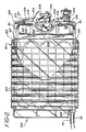
- Figure l shows various aspects of the system developed for extracorporeally treating a patient based in part upon the scientific discoveries of Edelson.
- the specific design, construction and operation of the apparatus l0 is the result of a number of separate inventions some of which form the subject matter of previously described issued US patents and published European appliations.
- the operation of the device and performance of the methods can be divided into two basic phases or modes, depicted in part by Figure l.
- the first phase is shown substantially in Figure l wherein the patient is connected at the point shown, preferably by venipuncture or the like methods well-known and developed to a high degree in the dialysis arts.
- Patient blood as it flows to the apparatus l0 (alternately referred to herein as the puvapheresis apparatus or system) is preferably infused, under control of pump ll, with an anticoagulant agent contained in container 20 hung from stand l5.
- clamping means l6a which has the dual function of also controlling flow in the reverse direction as well as flow to return container 2l.
- Clamp l6a acts as an "or" valve and will be described in greater detail later.
- blood pump l2 preferably a roller pump such as that described in U.S. Patent No. 4,487,558 to Troutner entitled “Improved Peristaltic Pump” and incorporated herein by reference
- This continuous centrifuge available commercially from suppliers such as Dideco, Haemonetics and others, is preferably capable of continuously separating blood based on the differing densities of the individual blood components.
- Continuous means that, as blood flows into the centrifuge through line 24, it accumulates within the rotating centrifuge bowl and is separated so that low density components are emitted after a certain minimum volume has been reached within the centrifuge bowl and as additional blood is added.
- the continuous centrifuge in effect acts as a hybrid between a pure online system and a pure batch system. This occurs because the centrifuge bowl has a capacity to hold most, if not all, of the most dense portion, typically erythrocytes or red blood cells while emitting lower density portions such as plasma and leukocytes (white blood cells) as whole blood is continuously added. At some point, however, the reservoir volume of the centrifuge is filled with the higher density components and further separation cannot be effectively obtained. Prior to that point, the operator, by viewing the uppermost portion of the centrifuge bowl through the centrifuge cover, can detect qualitatively when the centrifuge emits plasma (as opposed to priming solution).
- leukocyte enriched portions and the remainder, i.e., nonleukocyte enriched portions, including erythrocyte enriched portions.
- control panel l9 the identification of the individual blood portions as they are emitted from the centrifuge.
- keys 44 e.g. PLASMA, BUFFY COAT or leukocyte enriched portion
- the apparatus l0 controls valve mechanism l6c to direct the leukocyte enriched portion and a predetermined volume of plasma into plasma-leukocyte enriched container 22 while excess plasma, air, priming fluids, erythrocytes etc. are directed to container 2l.
- the operator directs that the bowl be emptied by suitable data key entry on panel l9 and the fluid contents of centrifuge l3 are advantageously pumped into return container 2l by means of pump l2 under the control of valves l6a and c.
- the foregoing steps may be repeated a number of times or cycles before the desired volume of leukocyte enriched blood and plasma is obtained for further treatment, in each instance the undesired portions being collected in return container 2l.
- the fluids including erythrocytes which have been pumped into return bag 2l are gravity fed back to the patient through a drip infusion operation and controlled by valve l6b. It is preferred that gravity feed by employed rather than pumping the blood back to the patient via pump l2 in order to avoid potential pressurization problems at the infusion insertion site at the patient, and also to avoid foaming or other air related dangers.
- the centrifuge bowl and line 24 may be expected to contain sterilized air which is preferably removed by suitable priming operations advantageously accomplished by utilizing the anticoagulation agent in container 20; both the air and a portion of priming solution being collected in container 2l.
- These volumes are selected largely in accordance with the individual volume capacities of the containers as well as the treatment irradiation chamber to be described later. Accordingly, these volumes are set in order to preferably optimize handling efficiency and to ensure patient safety. For instance, one preferred selection would include the following settings: 250 ml total buffy coat or leukocyte enriched portion and 300 ml of plasma to be collected within container 22. This might require any number of cycles, preferably on the order of three or four, bearing in mind that the more cycles that are selected, the lower the total volume of blood withdrawn from the patient at any one time. If blood collection meets the minimum capacity limits of the centrifuge bowl, the patient's capacity to withstand temporary blood volume depletions and the treatment procedure in general is increased.
- the leukocyte enriched container 22 is connected via tubing line 34 to the flat plate treatment chamber behind chamber assembly door l7 with a return line 35 to reservoir container 22.
- the leukocyte enriched blood, plasma, and priming solution contained in reservoir 22 is delivered through line 34 to the inlet of the flat plate irradiation chamber 200, upward through the flat plate cavity in the chamber to the outlet.
- Tubing from the outlet passes through a pump block, affixed to the end of the flat plate irradiation chamber, and then connects to return line 35 which returns fluids from the chamber to container 22.
- a recirculation roller pump-type rotor located internally in the machine, engages the tubing in the pump block in the semi-circular tract and thereby provides and controls the recirculating flow of fluid from container 22 up through the flat plate irradiation chamber and back to container 22.
- the tubing line associated with the flat plate irradiator preferably incorporates a thermocouple for monitoring the fluid temperature.
- Sterile air, initially contained in the irradiation chamber cavity is advantageously displaced by entering fluid and stored in the top portion of container 22.
- the air stored in container 22 can be pumped back into the outlet of the irradiation chamber thereby displacing all fluids back into container 22.
- the irradiation chamber is fluid filled and the BUFFY COAT button on panel l9 is pressed, the light array assembly which surrounds the chamber is energized.
- the recirculation roller pump rotor results in recirculation of the leukocyte enriched fluid from container 22 through the chamber and the energized light array assembly and back to container 22.
- the photoactivating irradiation of the leukocyte enriched fluid is initiated at the outset and continues through and after the collection and separation process.
- the exposure time is set via panel l9 in accordance with physician determined criteria.
- the central control means of the apparatus l0 calculates and displays via central processing unit and memory stored software, the exposure time remaining at the onset of irradiation treatment and as the treatment progresses.
- Another portion of the control panel l9 also preferably includes three operator controlled entry data keys whereby the operator can de-energize the light array and stop the recirculation process if desired.
- Actual photoirradiation treatment commences automatically under control of the central processing unit when fluid is first directed to container 22.
- the leukocyte enriched portion of the blood collected within container 22, is pumped through tubing set 34, through the treatment cassette, through return line 35, and back into reservoir 22. This continues until the preset exposure time has expired whereupon the light array is de-energized and the recirculation roller pump reverses emptying the contents of the irradiation cassette into container 22.
- container 22 is ideally removed to stand l5 where it is connected to tube 36 provided on the drip chamber 2la, associated with return container 2l, for reinfusion of the treated blood portion into the patient.
- container 22 would ideally have four connection points or ports; one for the collection of the leukocyte enriched blood portion, two for connection to the flat plate irradiation cassette, and the fourth for connection to the drip chamber for reinfusion of treated blood to the patient.
- the control panel l9 of the apparatus l0 is shown with the keyboard entry buttons 44, each ideally having a light which, when lit, preferably indicates the state of the operation.
- the keyboard entry buttons 44 are preferably placed in sequential order thereby assisting the operator in learning the system and performing the steps in the correct order.
- the central control microprocessor will preferably be programmed to prevent out of step sequences from being implemented.
- a visual display indicates the volume of leukocyte enriched blood collected in container 22.
- Panel l9 will preferably also contain a power switch, as well as a blood pump speed control whereby the operator may select the speed with which the blood is withdrawn from the patient and pumped through the system during collection.
- a power switch as well as a blood pump speed control whereby the operator may select the speed with which the blood is withdrawn from the patient and pumped through the system during collection.
- an alpha-numeric display for indicating the machine's status and identifying alarm conditions throughout system operation.
- Optional accessory status lights preferably provided in green, yellow, and red colors, provide at a glance the overall operating status of apparatus l0.
- a mute reset button for quieting an audible alarm activated in the event an alarm condition occurs and operator input is required.
- side panel 23 will preferably include mechanical means (e.g. hanging pegs and the like) for assisting in the securement of container 22. It may also optionally be outfitted with a transparent or translucent opening l8b in the area beneath container 22 for providing at a glance information regarding the illumination status of the irradiation treatment cassette during the treatment phase. For instance, if the window is of sufficient size, the operator may readily determine that each irradiation source within the treatment cassette is illuminated as desired. Naturally, the material comprising such window is preferably selected in order to contain harmful radiation, if any, within apparatus l0.
- the aforedescribed photopheresis blood treatment apparatus is made largely possible by an automated control method for directing the blood portions, derived from the continuous centrifuge, into particular containers.
- the automated method performs in accordance with preset volume determinations which are manually entered behind panel l8a pursuant to a physician's direction.
- These predetermined volumes specify the volume to be contained within container 22 by setting forth the volume of plasma and the volume of leukocyte enriched blood portion to be directed thereto. Additionally included within these condition setting parameters is preferably the ability to set forth the number of cycles of blood collection and separation required or desired in order to obtain the desired blood volumes.
- the volumes collected are determined in accordance with the blood volume pumped by the blood pump. This may be suitably monitored and communicated to the central control means by specifically monitoring the number of step pulses input to the pump to cause rotation of the blood pump. Typically, 200 pulses results in one revolution. Rotation may also be conveniently monitored such as by attachment of a slotted disk to the shaft and the passage of slots determined by an optical sensor means such as described in US-A-4 623 328 and by monitoring shaft rotation. The resultant periodic signal may be conveniently correlated with speed and number of rotations by circuit designs well-known in the art. The number of rotations by any of the foregoing methods coupled with the known volume pumping characteristics of the pump , will provide the necessary information regarding the volume of blood pumped. It will readily be appreciated that the sensors need not be optical but may be electronic or mechanical instead.
- a most preferred procedure would be as follows.
- the operator presses the PRIME CENT. key on control panel section l9 which primes the tubing set, the blood pump, and the centrifuge with the anticoagulation solution contained in container 20. Displaced sterile air is collected in container 2l.
- PRIME UV key on control panel section 42 which closes the tubing line to container 2l and opens the tubing line to container 22 by means of valve l6c.
- Recirculation roller pump rotor 203 is energized to prime the flat plate irradiation chamber and collects displace sterile air to container 22.
- the priming process stops automatically after a preset volume of fluid is delivered to container 22.
- Blood collection is started by the operator pressing START key on control panel section l9. Thereafter, blood is withdrawn from the patient and pumped by the blood pump into the rotating centrifuge. As the blood enters the centrifuge, it displaces the priming solution which emerges first in accordance with its preferably lighter density. This priming solution is automatically directed into container 22 until a preset volume is delivered, after which the emerging solution is redirected to container 2l by means of valve l6c. At some point, the priming solution will be completely displaced from the rotating centrifuge and plasma will begin to emerge. This emergence may be directly observed through port l4 whereupon the operator presses the PLASMA key on control panel section l9.
- the central control means automatically directs the plasma into container 22 by altering valve l6c keeping track of the volume as it does so since the volume entering the centrifuge equals the volume emerging therefrom. This continues until the operator indicates the leukocyte enriched portion, i.e. buffy coat has begun by pressing the respective data entry key in control panel section 42 whereupon, the leukocyte enriched portion continues to container 22, however, the volume so directed is monitored as buffy coat volume. Alternately, if all of the predetermined plasma volume is collected prior to the emergence of the buffy coat, then the central control means automatically diverts, by valve l6c, the emerging plasma fluid stream to container 2l. In that instance, upon the emergence of the buffy coat and the keying of the BUFFY COAT data entry switch 44, the central control means diverts the emerging buffy coat into container 22 by means of valve l6c, again keeping track of its volume.
- the collection of the buffy coat will preferably continue in accordance with both the predetermined buffy coat volume as well as the number of cycles, another condition predetermined by the physician. If this most preferred embodiment is employed, then a representative example might be as follows. Assume, that the predetermined volume and cycle conditions are set as follows: 350 mls of plasma, 250 mls of buffy coat, and 5 cycles. In each cycle, the apparatus will collect 250/5 or 50 mls of buffy coat before ending the cycle and thereupon emptying the centrifuge bowl and returning all nonleukocyte fluids, predominantly erythrocytes and perhaps excess plasma, to the patient. Prior to the collection of the 50 mls, plasma will emerge from the centrifuge and will be collected in container 22 either until the full 350 mls are collected or, until the buffy coat emerges.
- the central control means will direct the further collection of plasma, if needed, in order to reach the 350 ml predetermined volume and then collect an additional 50 mls of buffy coat.
- the total volume to be contained within container 22, will then equal 600 mls and would be indicated on display 46 as it is accumulated.
- the instant invention serves to automatically keep track of the volumes as they are collected thereby facilitating the institution of a convenient number of cycles whereby the removal of large blood volumes from the patient is avoided. Not only is patient safety enhanced thereby, but the automated nature of the procedure further increases safety since, in accordance with the programmed conditions supplied to the central control microprocessor, the operator need not attempt to keep track of plasma and leukocyte enriched volumes collected, while still being assured that the final solution for treatment will contain the predetermined and desirable leukocyte concentration.
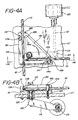
- FIG. 4a and b depicted are top and side views of a pivoting "or" valve shown in Figure l as l6a.
- Tubing portion lll is connected to the patient and leads alternately to tubing ll2 connected to the return container 2l ( Figure l) and to tubing ll0 which leads toward the blood pump l2 ( Figure l).
- the tubing sections lll and ll2 rest against block means ll6 which is fixedly mounted on work surface ll7.
- Clamping means l30 is mounted on rotatable shaft l22 extending through bearing l25 which is mounted in fixed block ll6.
- Clamp edges ll3b and ll4b operate alternately to squeeze tubing sections lll and ll2 respectively against fixed post or anvils ll3a and ll4a respectively. When activated, the respective clamping edges will preferably pinch the lines into full occlusion or permit free flow.
- Motion translator ll5 is affixed to shaft l22.
- Actuator shaft l2l is pivotally mounted to the opposite end of the motion translator ll5 by pivot means l23.
- Actuator shaft l2l is additionally attached to linear actuator stepper motor l20.
- the clamp will optionally include slotted plates ll8A and ll8B, affixed to block ll6, for advantageously retaining tubing lll and ll2 respectively in position for clamping.
- a manual override feature is desirable in order to facilitate the mounting and unmounting of tubing sets.
- the means for engaging and disengaging shaft l22 and clamping means l30 is shown in top view in Figure 4C, and cut-away side view in Figures 4D and 4E.
- Shaft l22 is affixed to hollow cylindrical pivot block l26 which can rotate within cylindrical sleeve l27.
- Sleeve l27 is firmly affixed to clamping means l30.
- plunger l3l having a narrow diameter portion l3la and a wide diameter portion l3lb, and guide rod l3lc.
- Compression spring l32 biases plunger l3l in an upward direction whereupon the wide diameter portion l3lb aligns with balls l29 causing the balls l29 to enter holes l28a.
- the balls l29 securely lock pivot block l26 together with sleeve l27 and all forces generated by linear actuator stepper motor l20 are transmitted through shaft l22 to clamp means ll3 and ll4.
- button l33 is affixed to the extension of plunger l3l.
- Figure series 5 shows an "on/off" valve employed as valve l6b for controlling return flow from container 2l to the patient as well as for preventing inadvertent flow into container 2l.
- the servo actuator motor l20 actuator shaft l2l, and motion translator ll5 are substantially the same although obvious mechanical variations may be substituted.
- clamping means l40 and fixed block means l45 is rectangular shaped rather than triangularly shaped, as in the Figure 4 "or” valve, clamping edge l4lb pinches line l43 against anvil l4la in a similar manner.
- the disengaging mechanism shown in Figures 4C, 4D, and 4E may be identically used in the Figure 5 on/off valve.
Landscapes
- Health & Medical Sciences (AREA)
- Heart & Thoracic Surgery (AREA)
- Pulmonology (AREA)
- Engineering & Computer Science (AREA)
- Anesthesiology (AREA)
- Biomedical Technology (AREA)
- Hematology (AREA)
- Life Sciences & Earth Sciences (AREA)
- Animal Behavior & Ethology (AREA)
- General Health & Medical Sciences (AREA)
- Public Health (AREA)
- Veterinary Medicine (AREA)
- External Artificial Organs (AREA)
- Heating, Cooling, Or Curing Plastics Or The Like In General (AREA)
- Cultivation Of Seaweed (AREA)
- Indication Of The Valve Opening Or Closing Status (AREA)
Priority Applications (1)
| Application Number | Priority Date | Filing Date | Title |
|---|---|---|---|
| AT87301722T ATE59785T1 (de) | 1986-02-27 | 1987-02-26 | Ventileinrichtung fuer ein system zur behandlung eines patienten durch photoaktivierung. |
Applications Claiming Priority (2)
| Application Number | Priority Date | Filing Date | Title |
|---|---|---|---|
| US06/834,303 US4681568A (en) | 1984-10-29 | 1986-02-27 | Valve apparatus for photoactivation patient treatment system |
| US834303 | 1986-02-27 |
Publications (2)
| Publication Number | Publication Date |
|---|---|
| EP0241123A1 true EP0241123A1 (fr) | 1987-10-14 |
| EP0241123B1 EP0241123B1 (fr) | 1991-01-09 |
Family
ID=25266619
Family Applications (1)
| Application Number | Title | Priority Date | Filing Date |
|---|---|---|---|
| EP87301722A Expired - Lifetime EP0241123B1 (fr) | 1986-02-27 | 1987-02-26 | Appareil à soupape pour un système de traitement d'un patient par photoactivation |
Country Status (10)
| Country | Link |
|---|---|
| US (1) | US4681568A (fr) |
| EP (1) | EP0241123B1 (fr) |
| JP (1) | JPS62224366A (fr) |
| AT (1) | ATE59785T1 (fr) |
| AU (1) | AU6950787A (fr) |
| CA (1) | CA1288755C (fr) |
| DE (1) | DE3767196D1 (fr) |
| ES (1) | ES2020264B3 (fr) |
| PH (1) | PH23685A (fr) |
| ZA (1) | ZA871406B (fr) |
Cited By (1)
| Publication number | Priority date | Publication date | Assignee | Title |
|---|---|---|---|---|
| EP1698371A1 (fr) * | 2005-03-04 | 2006-09-06 | LIFEBRIDGE Medizintechnik AG | Pince à action rapide pour obturer un tube souple |
Families Citing this family (20)
| Publication number | Priority date | Publication date | Assignee | Title |
|---|---|---|---|---|
| NO171427C (no) * | 1990-05-25 | 1993-03-10 | Trallfa Robot Abb As | Regulerbar styreventil for stroemningsregulering av gass eller vaeske samt anvendelse av saadan ventil |
| US5569928A (en) * | 1993-12-14 | 1996-10-29 | Therakos, Inc | Photoactivation light array |
| JPH08506984A (ja) * | 1993-12-22 | 1996-07-30 | バクスター、インターナショナル、インコーポレイテッド | 向上された可視性を有する自己プライミング滴下チャンバー |
| US5482440A (en) * | 1993-12-22 | 1996-01-09 | Baxter Int | Blood processing systems using a peristaltic pump module with valve and sensing station for operating a peristaltic pump tube cassette |
| US5746708A (en) * | 1993-12-22 | 1998-05-05 | Baxter International Inc. | Peristaltic pump tube holder with pump tube shield and cover |
| US5445506A (en) * | 1993-12-22 | 1995-08-29 | Baxter International Inc. | Self loading peristaltic pump tube cassette |
| US5484239A (en) * | 1993-12-22 | 1996-01-16 | Baxter International Inc. | Peristaltic pump and valve assembly for fluid processing systems |
| US5462416A (en) * | 1993-12-22 | 1995-10-31 | Baxter International Inc. | Peristaltic pump tube cassette for blood processing systems |
| US5427509A (en) * | 1993-12-22 | 1995-06-27 | Baxter International Inc. | Peristaltic pump tube cassette with angle pump tube connectors |
| US5480294A (en) * | 1993-12-22 | 1996-01-02 | Baxter International Inc. | Peristaltic pump module having jaws for gripping a peristaltic pump tube cassett |
| US5711654A (en) * | 1995-06-07 | 1998-01-27 | Baxter International Inc. | Peristaltic pump with rotor position sensing employing a reflective object sensor |
| AU710242B2 (en) * | 1996-03-29 | 1999-09-16 | Therakos, Inc. | Photopheresis treatment of leukocytes |
| WO1997037536A1 (fr) | 1996-04-09 | 1997-10-16 | Therakos, Inc. | Procede d'elimination de psoralenes dans des fluides biologiques |
| US5951509A (en) * | 1996-11-22 | 1999-09-14 | Therakos, Inc. | Blood product irradiation device incorporating agitation |
| WO1999002215A1 (fr) * | 1997-07-10 | 1999-01-21 | Therakos, Inc. | Traitement des affections inflammatoires de l'intestin et de la vessie |
| US6219584B1 (en) | 1999-07-09 | 2001-04-17 | Therakos, Inc. | Method and system for determining an effective amount of light energy to delivery to fluids having targets for the light energy |
| US6495366B1 (en) | 1999-09-03 | 2002-12-17 | Therakos, Inc. | Uninterrupted flow pump apparatus and method |
| US8722422B2 (en) | 1999-09-03 | 2014-05-13 | Therakos, Inc. | Uninterrupted flow pump apparatus and method |
| US6793643B1 (en) | 2000-04-21 | 2004-09-21 | Therakos, Inc. | Low extracorporeal volume treatment system |
| JP2004065737A (ja) * | 2002-08-08 | 2004-03-04 | Nemoto Kyorindo:Kk | 薬液注入装置 |
Citations (19)
| Publication number | Priority date | Publication date | Assignee | Title |
|---|---|---|---|---|
| US2471623A (en) * | 1944-12-19 | 1949-05-31 | Adrian O Hubbell | Apparatus for handling fluids |
| DE2533315A1 (de) * | 1975-02-28 | 1976-09-09 | Ivac Corp | Steuersystem fuer die pumpen von injektionsspritzen und fuer die motordrehrichtung |
| FR2439022A1 (fr) * | 1978-10-17 | 1980-05-16 | Viggo Ab | Ensemble comprenant un catheter ou une canule |
| US4321919A (en) | 1979-12-11 | 1982-03-30 | Leukocyte Research, Inc. | Method and system for externally treating human blood |
| WO1982001651A1 (fr) * | 1980-11-07 | 1982-05-27 | Corp Ivac | Mecanisme combine de charge et de verrou pour des appareils de commande de fluide |
| GB2100143A (en) * | 1981-06-12 | 1982-12-22 | Edelson Richard Leslie | Treatment of blood to reduce lymphocyte population |
| US4398906A (en) | 1979-12-11 | 1983-08-16 | Frederic A. Bourke, Jr. | Method for externally treating the blood |
| US4428744A (en) | 1979-12-11 | 1984-01-31 | Frederic A. Bourke, Jr. | Method and system for externally treating the blood |
| US4464166A (en) | 1981-06-12 | 1984-08-07 | Frederic A. Bourke, Jr. | Method for externally treating the blood |
| US4487558A (en) | 1982-08-23 | 1984-12-11 | Extracorporeal Medical Specialties, Inc. | Peristaltic pump |
| EP0138489A1 (fr) | 1983-09-29 | 1985-04-24 | McNeilab, Inc. | Appareil et procédés pour traiter des cellules par irradiation |
| US4568328A (en) | 1984-10-29 | 1986-02-04 | Extracorporeal Medical Specialties, Inc. | Automated photophoresis blood portion control methods and apparatus |
| US4573962A (en) | 1984-10-29 | 1986-03-04 | Extracorporeal Medical Specialties, Inc. | Cassette drawer assembly for photoactivation patient treatment system |
| US4573960A (en) | 1984-10-29 | 1986-03-04 | Extracorporeal Medical Specialties, Inc. | Three phase irradiation treatment process |
| US4573961A (en) | 1984-10-29 | 1986-03-04 | Extracorporeal Medical Specialties, Inc. | Electronic control methods for puvapheresis apparatus |
| US4578056A (en) | 1984-10-29 | 1986-03-25 | Extracorporeal Medical Specialties, Inc. | Patient photopheresis treatment apparatus and method |
| EP0184391A2 (fr) * | 1984-11-29 | 1986-06-11 | Minnesota Mining And Manufacturing Company | Clapet de séquence pour l'administration intraveineuse en califourchon |
| US4596547A (en) | 1984-10-29 | 1986-06-24 | Mcneilab, Inc. | Valve apparatus for photoactivation patient treatment system |
| US4623328A (en) | 1984-10-29 | 1986-11-18 | Mcneilab, Inc. | Pump monitor for photoactivation patient treatment system |
Family Cites Families (5)
| Publication number | Priority date | Publication date | Assignee | Title |
|---|---|---|---|---|
| GB1114247A (en) * | 1964-06-01 | 1968-05-22 | Holger Hesse | Infusion apparatus |
| US3575161A (en) * | 1968-03-07 | 1971-04-20 | Seymour B London | Valve for biological systems |
| US3932065A (en) * | 1973-07-26 | 1976-01-13 | Coulter Electronics, Inc. | Pneumatically controlled liquid transfer system |
| US4061142A (en) * | 1976-06-16 | 1977-12-06 | Sandoz, Inc. | Apparatus for controlling blood flow |
| US4282902A (en) * | 1979-05-04 | 1981-08-11 | Becton Dickinson & Company | Valve apparatus for simultaneous control of a plurality of fluid paths |
-
1986
- 1986-02-27 US US06/834,303 patent/US4681568A/en not_active Expired - Lifetime
-
1987
- 1987-02-25 CA CA000530594A patent/CA1288755C/fr not_active Expired - Lifetime
- 1987-02-26 ZA ZA871406A patent/ZA871406B/xx unknown
- 1987-02-26 EP EP87301722A patent/EP0241123B1/fr not_active Expired - Lifetime
- 1987-02-26 PH PH34913A patent/PH23685A/en unknown
- 1987-02-26 AT AT87301722T patent/ATE59785T1/de not_active IP Right Cessation
- 1987-02-26 ES ES87301722T patent/ES2020264B3/es not_active Expired - Lifetime
- 1987-02-26 DE DE8787301722T patent/DE3767196D1/de not_active Expired - Lifetime
- 1987-02-26 AU AU69507/87A patent/AU6950787A/en not_active Abandoned
- 1987-02-27 JP JP62043274A patent/JPS62224366A/ja active Pending
Patent Citations (19)
| Publication number | Priority date | Publication date | Assignee | Title |
|---|---|---|---|---|
| US2471623A (en) * | 1944-12-19 | 1949-05-31 | Adrian O Hubbell | Apparatus for handling fluids |
| DE2533315A1 (de) * | 1975-02-28 | 1976-09-09 | Ivac Corp | Steuersystem fuer die pumpen von injektionsspritzen und fuer die motordrehrichtung |
| FR2439022A1 (fr) * | 1978-10-17 | 1980-05-16 | Viggo Ab | Ensemble comprenant un catheter ou une canule |
| US4428744A (en) | 1979-12-11 | 1984-01-31 | Frederic A. Bourke, Jr. | Method and system for externally treating the blood |
| US4321919A (en) | 1979-12-11 | 1982-03-30 | Leukocyte Research, Inc. | Method and system for externally treating human blood |
| US4398906A (en) | 1979-12-11 | 1983-08-16 | Frederic A. Bourke, Jr. | Method for externally treating the blood |
| WO1982001651A1 (fr) * | 1980-11-07 | 1982-05-27 | Corp Ivac | Mecanisme combine de charge et de verrou pour des appareils de commande de fluide |
| US4464166A (en) | 1981-06-12 | 1984-08-07 | Frederic A. Bourke, Jr. | Method for externally treating the blood |
| GB2100143A (en) * | 1981-06-12 | 1982-12-22 | Edelson Richard Leslie | Treatment of blood to reduce lymphocyte population |
| US4487558A (en) | 1982-08-23 | 1984-12-11 | Extracorporeal Medical Specialties, Inc. | Peristaltic pump |
| EP0138489A1 (fr) | 1983-09-29 | 1985-04-24 | McNeilab, Inc. | Appareil et procédés pour traiter des cellules par irradiation |
| US4568328A (en) | 1984-10-29 | 1986-02-04 | Extracorporeal Medical Specialties, Inc. | Automated photophoresis blood portion control methods and apparatus |
| US4573962A (en) | 1984-10-29 | 1986-03-04 | Extracorporeal Medical Specialties, Inc. | Cassette drawer assembly for photoactivation patient treatment system |
| US4573960A (en) | 1984-10-29 | 1986-03-04 | Extracorporeal Medical Specialties, Inc. | Three phase irradiation treatment process |
| US4573961A (en) | 1984-10-29 | 1986-03-04 | Extracorporeal Medical Specialties, Inc. | Electronic control methods for puvapheresis apparatus |
| US4578056A (en) | 1984-10-29 | 1986-03-25 | Extracorporeal Medical Specialties, Inc. | Patient photopheresis treatment apparatus and method |
| US4596547A (en) | 1984-10-29 | 1986-06-24 | Mcneilab, Inc. | Valve apparatus for photoactivation patient treatment system |
| US4623328A (en) | 1984-10-29 | 1986-11-18 | Mcneilab, Inc. | Pump monitor for photoactivation patient treatment system |
| EP0184391A2 (fr) * | 1984-11-29 | 1986-06-11 | Minnesota Mining And Manufacturing Company | Clapet de séquence pour l'administration intraveineuse en califourchon |
Cited By (2)
| Publication number | Priority date | Publication date | Assignee | Title |
|---|---|---|---|---|
| EP1698371A1 (fr) * | 2005-03-04 | 2006-09-06 | LIFEBRIDGE Medizintechnik AG | Pince à action rapide pour obturer un tube souple |
| US7367540B2 (en) | 2005-03-04 | 2008-05-06 | Lifebridge Medizintechnik Ag | Fast closing clamp |
Also Published As
| Publication number | Publication date |
|---|---|
| US4681568A (en) | 1987-07-21 |
| ES2020264B3 (es) | 1991-08-01 |
| DE3767196D1 (de) | 1991-02-14 |
| AU6950787A (en) | 1987-09-03 |
| JPS62224366A (ja) | 1987-10-02 |
| ATE59785T1 (de) | 1991-01-15 |
| ZA871406B (en) | 1988-10-26 |
| CA1288755C (fr) | 1991-09-10 |
| EP0241123B1 (fr) | 1991-01-09 |
| PH23685A (en) | 1989-09-27 |
Similar Documents
| Publication | Publication Date | Title |
|---|---|---|
| US4692138A (en) | Pump block for interfacing irradiation chamber to photoactivation patient treatment system | |
| US4737140A (en) | Irradiation chamber for photoactivation patient treatment system | |
| EP0241123B1 (fr) | Appareil à soupape pour un système de traitement d'un patient par photoactivation | |
| US4623328A (en) | Pump monitor for photoactivation patient treatment system | |
| EP0240149B1 (fr) | Installation d'éclairage destinée à un système de traitement d'un patient par photoactivation | |
| US4596547A (en) | Valve apparatus for photoactivation patient treatment system | |
| EP0181732B1 (fr) | Appareil automatisé pour l'irradiation de parties du sang | |
| US4578056A (en) | Patient photopheresis treatment apparatus and method | |
| US4573961A (en) | Electronic control methods for puvapheresis apparatus | |
| US4573960A (en) | Three phase irradiation treatment process | |
| EP0239255A1 (fr) | Pompe péristaltique démontable pour un système de traitement d'un patient par photoactivation | |
| US4573962A (en) | Cassette drawer assembly for photoactivation patient treatment system | |
| US4643710A (en) | Valve apparatus for photoactivation patient treatment system | |
| EP0242031B1 (fr) | Raccord à force d'insertion nulle pour un système de traitement d'un patient par photoactivation | |
| EP0240152B1 (fr) | Chambre d'irradiation pour un système de traitement d'un patient par photoactivation | |
| EP0239256A1 (fr) | Système en ligne de traitement simultané par irradiation |
Legal Events
| Date | Code | Title | Description |
|---|---|---|---|
| PUAI | Public reference made under article 153(3) epc to a published international application that has entered the european phase |
Free format text: ORIGINAL CODE: 0009012 |
|
| AK | Designated contracting states |
Kind code of ref document: A1 Designated state(s): AT BE DE ES FR GB IT SE |
|
| 17P | Request for examination filed |
Effective date: 19880317 |
|
| 17Q | First examination report despatched |
Effective date: 19891213 |
|
| GRAA | (expected) grant |
Free format text: ORIGINAL CODE: 0009210 |
|
| AK | Designated contracting states |
Kind code of ref document: B1 Designated state(s): AT BE DE ES FR GB IT SE |
|
| REF | Corresponds to: |
Ref document number: 59785 Country of ref document: AT Date of ref document: 19910115 Kind code of ref document: T |
|
| REF | Corresponds to: |
Ref document number: 3767196 Country of ref document: DE Date of ref document: 19910214 |
|
| ET | Fr: translation filed | ||
| ITF | It: translation for a ep patent filed | ||
| PLBE | No opposition filed within time limit |
Free format text: ORIGINAL CODE: 0009261 |
|
| STAA | Information on the status of an ep patent application or granted ep patent |
Free format text: STATUS: NO OPPOSITION FILED WITHIN TIME LIMIT |
|
| 26N | No opposition filed | ||
| EAL | Se: european patent in force in sweden |
Ref document number: 87301722.2 |
|
| REG | Reference to a national code |
Ref country code: GB Ref legal event code: IF02 |
|
| PGFP | Annual fee paid to national office [announced via postgrant information from national office to epo] |
Ref country code: SE Payment date: 20020206 Year of fee payment: 16 |
|
| PGFP | Annual fee paid to national office [announced via postgrant information from national office to epo] |
Ref country code: FR Payment date: 20020212 Year of fee payment: 16 |
|
| PGFP | Annual fee paid to national office [announced via postgrant information from national office to epo] |
Ref country code: ES Payment date: 20020213 Year of fee payment: 16 Ref country code: AT Payment date: 20020213 Year of fee payment: 16 |
|
| PGFP | Annual fee paid to national office [announced via postgrant information from national office to epo] |
Ref country code: GB Payment date: 20020227 Year of fee payment: 16 |
|
| PGFP | Annual fee paid to national office [announced via postgrant information from national office to epo] |
Ref country code: DE Payment date: 20020314 Year of fee payment: 16 |
|
| PGFP | Annual fee paid to national office [announced via postgrant information from national office to epo] |
Ref country code: BE Payment date: 20020418 Year of fee payment: 16 |
|
| PG25 | Lapsed in a contracting state [announced via postgrant information from national office to epo] |
Ref country code: GB Free format text: LAPSE BECAUSE OF NON-PAYMENT OF DUE FEES Effective date: 20030226 Ref country code: AT Free format text: LAPSE BECAUSE OF NON-PAYMENT OF DUE FEES Effective date: 20030226 |
|
| PG25 | Lapsed in a contracting state [announced via postgrant information from national office to epo] |
Ref country code: SE Free format text: LAPSE BECAUSE OF NON-PAYMENT OF DUE FEES Effective date: 20030227 Ref country code: ES Free format text: LAPSE BECAUSE OF NON-PAYMENT OF DUE FEES Effective date: 20030227 |
|
| PG25 | Lapsed in a contracting state [announced via postgrant information from national office to epo] |
Ref country code: BE Free format text: LAPSE BECAUSE OF NON-PAYMENT OF DUE FEES Effective date: 20030228 |
|
| PG25 | Lapsed in a contracting state [announced via postgrant information from national office to epo] |
Ref country code: DE Free format text: LAPSE BECAUSE OF NON-PAYMENT OF DUE FEES Effective date: 20030902 |
|
| EUG | Se: european patent has lapsed | ||
| GBPC | Gb: european patent ceased through non-payment of renewal fee | ||
| PG25 | Lapsed in a contracting state [announced via postgrant information from national office to epo] |
Ref country code: FR Free format text: LAPSE BECAUSE OF NON-PAYMENT OF DUE FEES Effective date: 20031031 |
|
| REG | Reference to a national code |
Ref country code: FR Ref legal event code: ST |
|
| REG | Reference to a national code |
Ref country code: ES Ref legal event code: FD2A Effective date: 20030227 |
|
| PG25 | Lapsed in a contracting state [announced via postgrant information from national office to epo] |
Ref country code: IT Free format text: LAPSE BECAUSE OF NON-PAYMENT OF DUE FEES;WARNING: LAPSES OF ITALIAN PATENTS WITH EFFECTIVE DATE BEFORE 2007 MAY HAVE OCCURRED AT ANY TIME BEFORE 2007. THE CORRECT EFFECTIVE DATE MAY BE DIFFERENT FROM THE ONE RECORDED. Effective date: 20050226 |