EP0241225A1 - Hakenfänger einer Einholvorrichtung für eine Langleine - Google Patents
Hakenfänger einer Einholvorrichtung für eine Langleine Download PDFInfo
- Publication number
- EP0241225A1 EP0241225A1 EP87302888A EP87302888A EP0241225A1 EP 0241225 A1 EP0241225 A1 EP 0241225A1 EP 87302888 A EP87302888 A EP 87302888A EP 87302888 A EP87302888 A EP 87302888A EP 0241225 A1 EP0241225 A1 EP 0241225A1
- Authority
- EP
- European Patent Office
- Prior art keywords
- hook
- guide track
- edge
- improvement
- advancement path
- Prior art date
- Legal status (The legal status is an assumption and is not a legal conclusion. Google has not performed a legal analysis and makes no representation as to the accuracy of the status listed.)
- Granted
Links
- 238000011144 upstream manufacturing Methods 0.000 claims description 29
- 230000003028 elevating effect Effects 0.000 abstract description 12
- 238000013459 approach Methods 0.000 description 2
- 241000251468 Actinopterygii Species 0.000 description 1
- 230000004075 alteration Effects 0.000 description 1
- 238000006243 chemical reaction Methods 0.000 description 1
- 230000000694 effects Effects 0.000 description 1
- 230000005484 gravity Effects 0.000 description 1
- 238000006467 substitution reaction Methods 0.000 description 1
Images



Classifications
-
- A—HUMAN NECESSITIES
- A01—AGRICULTURE; FORESTRY; ANIMAL HUSBANDRY; HUNTING; TRAPPING; FISHING
- A01K—ANIMAL HUSBANDRY; AVICULTURE; APICULTURE; PISCICULTURE; FISHING; REARING OR BREEDING ANIMALS, NOT OTHERWISE PROVIDED FOR; NEW BREEDS OF ANIMALS
- A01K91/00—Lines
- A01K91/18—Trotlines, longlines; Accessories therefor, e.g. baiting devices, lifters or setting reelers
Definitions
- This invention relates to improved longline hauling apparatus useful in bottom fishing and particularly to apparatus for hauling longline equipped with hooks.
- Longlines utilized in fishing include a ground line, a continuous line typically running from 2.000 to 10,000 feet long, equipped with a plurality of gangions that are spaced at intervals along the ground line. Hooks are affixed to the free ends of the gangions.
- a longline hauling and stowage apparatus of the type typically employed today is disclosed in United States Patent No. 4,505,062 issued to Harold T. Cook, Jr.
- the longline hauling and stowage apparatus is designed to capture and stow longlines equipped with conventional J hooks. While conventional J hooks are widely used, the circle hook has recently been gaining in popularity among fishermen.
- the circle hook differs from the conventional J hook in that its bend is much larger, relative to the length of the shank, and the point is curved so that in plan view the point is oriented nearly orthogonally to the shank as opposed to being parallel as it is in a conventional J hook.
- the present invention therefore, provides an improved means for capturing circle hooks so that the ground line, gangions and hooks can be stowed in an orderly manner for ready redeployment.
- the improved hook capturing means is intended in its preferred embodiment to be employed with an apparatus for retrieving longlines that includes a means for moving a ground line along an advancement path and a hook guide track positioned adjacent the advancement path for capturing and guiding hooks along a guide path defined by the guide track.
- the guide track has an initial portion spaced from and nonparallel with the advancement path and a primary portion smoothly joined with said initial portion and running adjacent to the advancement path.
- the improved hook capturing means is located immediately upstream from the initial portion of the guide track and comprises a hook turning means upstream from and adjacent the initial portion of the guide track for orienting the hook such that the shank passes between the guide track and the advancement path, and such that the point passes on the side of the guide track opposite from the advancement path, thereby allowing the guide track to engage the interior of the hook bend and capture the hook.
- the hook turning means defines a hook engaging surface having a first edge defining a portion of the boundary of the surface. The first edge terminates adjacent the side of the guide track opposite from the advancement path. The surface extends upstream from the first edge and adjacent the advancement path and defines a slot extending from the first edge to and through the advancement path.
- the ground line is hauled by the means for moving the ground line so that the ground line and gangions travel through the slot defined by the hook engaging surface.
- the hook is pulled toward the hook engaging surface. Since the hook engaging surface is upstream from the guide track, the hook engaging surface causes the hook to rotate in reaction to the forward advancement of the hook so that, as the hook reaches the location of the guide track, the point of the hook has been turned away from the advancement path and passes the side of the guide track opposite from the advancement path.
- the guide track is positioned below the advancement path so that the hook point is turned down by the hook engaging surface with the assistance of gravity.
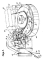
- the hauling and stowage apparatus is employed to retrieve a longline 22, made up of the ground line 24, to which are attached a plurality of gangions 26.
- Circle hooks 28 are affixed to the free ends of the gangions.
- the ground line engages a hauler sheave 30 that advances the ground line, first between a pair of entrance guide members 32 (left and right respectively when viewed in a downstream direction), which are normally employed to remove fish from the hooks.
- the ground line then traverses an idler sheave 36, from which it travels in a generally straight advancement path to the hauler sheave 30.
- a circle hook turning device 38 is positioned between the idler sheave 36 and the hauler sheave 30.
- the hook and gangion hang freely from the ground line.
- the hook 28 engages the guide track 34, the edge of which defines in plan view a guide surface.
- the guide track is preferably positioned below the advancement path of the ground line, and in plan view has an initial portion 34a which first intersects the advancement path of the ground line and gradually curves into a primary portion 34b that is generally equidistantly spaced from the ground line as it traverses a portion of the circumference of the hauler sheave 30.
- the ground line 24 is picked up by a pair of nip rolls 40, which pull the ground line from the hauler sheave 30 and deposit it in a stowage bin 42. While the ground line traverses the hauler sheave 30 and the nip rolls 40, the hook 28 remains engaged with the guide track 34 and is maintained in engagement with the guide track via an arcuate brush 44, having bristles that are oriented perpendicularly to the guide track. The hook traverses from the guide track 34 onto a stowage track 46 that is detachable from the hauling device, along with the stowage bin 42.
- the apparatus thus serves to retrieve the longline 22 and dispose the longline in coils in the stowage bin in an orderly manner so that it can be deployed without delay because of fouled hooks or tangled gangions. While the invention is disclosed in conjunction with a primary line hauler for retrieving a longline, the invention will function equally well with a secondary hauler used primarily to pick line from the deck of a ship and coil it in a storage bin.
- the hook turning device 38 is positioned immediately upstream from the initial portion 34a of the guide track.
- the hook turning device 38 is mounted on a vertically oriented wall 39 that is positioned on the left side of the ground line advancement path when viewing in a downstream direction.
- the wall 39 is spaced from the advancement path.
- the hook capturing device includes a hook engagement plate 50, having a left-hand section 50a and a right-hand section 50b when viewed in a downstream direction.
- the remaining components of the hook capturing device are a hook elevating ramp 52 positioned below the ground line advancement path, and a brush 54 having bristles that extend from a location above the ground line advancement path at an angle downstream and downwardly, so that the edges of the bristles project below the advancement path and engage the upper surface of the hook elevating ramp 52.
- the bristles of the brush 54 terminate upstream from the lower edge of the hook engagement plate.
- the hook elevating ramp 52 is also affixed to the vertical wall 39, but at a loction below the hook engagement plate 50.
- the elevating ramp 52 extends from a position well below the ground line advancement path in a smooth curve upwardly and in a downstream direction.
- the hook 28 dangling from a gangion 26 engages the hook elevating ramp 52 as the gangion rounds the idler sheave 36.
- the elevating ramp elevates the hook to a location immediately below the ground line.
- a forward lip plate 56 forms a downstream extension of the elevating ramp 52 and terminates in a downstream edge 58 that lies upstream from the engagement plate 50 and is spaced upstream from the initial portion 34a of the guide track 34.
- the downstream edge 58 of the lip plate 56 is horizontally spaced from the initial portion 34a of the guide track 34 by a distance slightly less than the length of a hook, that is, the distance from the hook eye to the hook bend.
- the downstream edge 58 is spaced from the lower edge of the hook engagement plate 50 by only a distance sufficient to allow the hook point to rotate downwardly as it engages the engagement plate.
- the primary function of the ramp is to elevate or present the hook at the level of the guide track prior to engaging the engagement plate.
- a horizontal plate can be substituted for the ramp if the line forwarding apparatus is constructed so that the hook is already presented at the guide track level.
- the ground line, gangion and hook advance to the top of the elevating ramp 52, the ground line and the gangion pass through the bristles of the brush 54.
- Bristles of the brush 54 serve especially to contain the gangion, and thus the hook, in close engagement with the elevating ramp 52 and the upper surface of the forward lip plate 56. In this manner, the hool is prevented from flying above the ground line advancement path, which might cause it to improperly engage with the hook engagement plate 50 or become entangled in the ground line.
- the brush also causes a hook that approaches it with the shank on the ramp, but the point in the air, to rotate one way or the other so that the hook lies flat on the ramp prior to contacting the engagement plate.
- a strong magnet positioned under the ramp at the brush location can function as a substitute for the brush.
- the hook engagement plate 50 comprises a left-hand section 50a and a right-hand section 50b.
- the left-hand section 50a has a lower edge that lies adjacent and parallel to and is in intimate contact with the initial portion 34a of the guide track 34.
- a slot 60 is formed in the hook engagement plate between the left-hand section 50a and the right-hand section 50b.
- the lower edge of the right-hand section 50b of the hook engagement plate 50, positioned adjacent the initial portion 34a of the guide track 34, is spaced from the guide track by a distance sufficient to let the bend of the hook 28 pass in an unrestricted manner between the lower edge of the right-hand section and the surface of the guide track 34.
- both sections 50a and 50b extend upwardly and in an upstream direction.
- the upstream face of the sections 50a and 50b presents a hook engaging surface of the hook engaging plate 50 that extends from a location above the ground line advancement path, downwardly and in a downstream direction.
- the slot 60 is sufficiently wide to allow the ground line and gangions to pass through the hook engagement plate 50, but is most preferably not wide enough to allow the hook 28 to pass through the slot when the hook point and shank are lying in a generally horizontal plane. That is, the width of the slot 60 is less than the distance across the hook bend.
- the hook 28 whether its point is lying to the left or the right of its shank, then engages the upstream surface of the engagement plate 50 and is rotated about its shank so that its point is then positioned below the lower edge of the initial portion 34a of the guide track 34, thus causing the hook to engage and be captured by the guide track.
- the engagement plate 50 is also canted from left to right in a downstream direction. This cant causes a hook that approaches the plate in a point up orientation to preferably rotate in a clockwise direction (looking downstream) as it contacts the engagement plate.
- the right-hand section 50b of the engagement plate 50 is hinged so that the downstream edge can rotate upwardly, thus allowing a knotted gangion or other material affixed to the hook to bypass the hook engagement device.
- the upstream end is affixed to a rod 64 which, in turn, is journaled in a bearing 66 affixed to the upstream end of the left-hand section 50a.
- the rod 64 extends through the wall 39 upon which the hook capturing device 38 is mounted and projects from its opposite side.
- a radially and downwardly extending arm 68 is affixed to the portion of the rod 64 extending through the wall on the side opposite the hook capturing device.
- One end of a coiled tension spring 70 is affixed to the lower end of the arm 68.
- the other end of the coiled tension spring 70 is affixed to a bracket 72, which is in turn affixed to the wall 39 at a location upstream from the arm 68. In this manner the rod 64 is rotationally biased such that the lower edge of the right-hand section 50b is biased in a downward direction.
- stop mechanism 74 comprises an arm 76 having one end 78a affixed to the forward surface of right-hand section 50b and a second end 78b that is elevated above the first end and that projects over the forward surface of left-hand section 50a.
- a screw 80 is threaded into an aperture 82 located adjacent the second end 78b of the arm 76.
- the aperture 82 is oriented so that the end of the screw 80 engages the upper surface of the left-hand section 50a.
- the location of the lower edge of the right-hand section 50b can be adjusted to position the lower edge in a desired location relative to the initial portion 34a of the guide track 34.
- the lower edge of the right-hand section 50b is positioned so that it is slightly below the midpoint of the downstream edge of the guide track 34.
- the right-hand section 50b is elevated, exposing the brush 54 that is positioned immediately upstream from the hook engagement plate 50. In this position, a knotted gangion, or a hook having material still engaging it, can clear the engagement plate without harming the gangion or the hook.
- a pair of rods, tines or stiff bristles can be substited for the sections of the hook engagement plate 50 and would function nearly as well as the preferred embodiment just described. It is preferred, however, that a relatively broad engagement surface, such as that created by the upstream face at the hook engagement plate, be employed to optimize the turning of the hook to engage the guide track 34.
- the functioning of the engagement surface made up of the right-hand section 50b can be enhanced by positioning a projection 86 that extends below the hook engaging surface adjacent the slot 60 and immediately upstream from the lower edge of the right-hand section 50b.
- the projection 86 is in the form of a small rod having a diameter that is less than the distance across the bend of the hook and which extends slightly below the guide track. As will be described in more detail below in conjunction with FIGURES 13, 14 and 15, the projection aids in turning the hook 28 so that it properly engages the guide track 34 when the hook point is lying to the right-hand side of the hook shank upon entering the hook turning device 38.
- a circle hook 28 is shown at a location lying atop the forward lip plate 56 with the point lying to the left of the shank just prior to engaging the upstream facing surface of the hook engagement plate 50.
- the point engages the engagement surface as indicated in FIGURE 9.
- the downwardly sloped engagement surface causes the hook to rotate in a counterclockwise direction as indicated by arrow 100, such that the tip of the point is brought to a location below the initial portion 34a of the guide track 34.
- the hook engages the guide track 34, as indicated in FIGURES 10, 11 and 12.
- FIGURES 13, 14 and 15 a circle hook 28 is shown with the point lying to the right of the shank. Because of the hook offset, when the point is to the right of the shank, the coaction of the upstream facing surface of the hook engagement plate 50 and the hook point will not always result in the hook point being rotated sufficiently so that it will properly engage the initial portion 34a of the guide track. Thus, the projection 86 is employed to engage the bend of the hook prior to the time that the point engages the engagement surface to begin rotating the hook well in advance of its arrival adjacent the guide track 34, as shown in FIGURES 16, 17 and 18.
Landscapes
- Life Sciences & Earth Sciences (AREA)
- Environmental Sciences (AREA)
- Animal Husbandry (AREA)
- Biodiversity & Conservation Biology (AREA)
- Brushes (AREA)
- Catching Or Destruction (AREA)
- Mechanical Means For Catching Fish (AREA)
Applications Claiming Priority (2)
| Application Number | Priority Date | Filing Date | Title |
|---|---|---|---|
| US851324 | 1986-04-11 | ||
| US06/851,324 US4750285A (en) | 1986-04-11 | 1986-04-11 | Hook capturing device for longline hauling apparatus |
Publications (2)
| Publication Number | Publication Date |
|---|---|
| EP0241225A1 true EP0241225A1 (de) | 1987-10-14 |
| EP0241225B1 EP0241225B1 (de) | 1992-09-02 |
Family
ID=25310509
Family Applications (1)
| Application Number | Title | Priority Date | Filing Date |
|---|---|---|---|
| EP87302888A Expired EP0241225B1 (de) | 1986-04-11 | 1987-04-02 | Hakenfänger einer Einholvorrichtung für eine Langleine |
Country Status (6)
| Country | Link |
|---|---|
| US (1) | US4750285A (de) |
| EP (1) | EP0241225B1 (de) |
| JP (1) | JPS62296827A (de) |
| CA (1) | CA1282239C (de) |
| IS (1) | IS1420B6 (de) |
| NO (1) | NO171091C (de) |
Cited By (1)
| Publication number | Priority date | Publication date | Assignee | Title |
|---|---|---|---|---|
| FR2633155A1 (fr) * | 1988-06-22 | 1989-12-29 | Inst Hochseefischerei | Unite de manipulation mecanisee de lignes longues notamment mono-fil, comprenant un dispositif de demelage |
Families Citing this family (1)
| Publication number | Priority date | Publication date | Assignee | Title |
|---|---|---|---|---|
| NO302501B1 (no) * | 1996-05-06 | 1998-03-16 | Mustad & Soen As | Fremgangsmate og egnemaskin til egning av fiskekroker |
Citations (2)
| Publication number | Priority date | Publication date | Assignee | Title |
|---|---|---|---|---|
| EP0082126A1 (de) * | 1981-12-15 | 1983-06-22 | O. MUSTAD & SON A.S | Hakenfänger einer Einholvorrichtung für eine Angelleine |
| GB2124863A (en) * | 1982-08-02 | 1984-02-29 | Hoseth Kaare | Improvements in or relating to a hook orientation device |
Family Cites Families (6)
| Publication number | Priority date | Publication date | Assignee | Title |
|---|---|---|---|---|
| US1768981A (en) * | 1929-06-06 | 1930-07-01 | Henrikson Gust | Trawl reel |
| US3377733A (en) * | 1965-09-21 | 1968-04-16 | Godo Einar | Machine for handling a halibut long line and the like |
| US4107865A (en) * | 1977-01-28 | 1978-08-22 | Alex Wayne E | Long line coiling apparatus |
| US4266359A (en) * | 1979-10-09 | 1981-05-12 | Alex Wayne E | Long line hook arranging apparatus |
| US4461112A (en) * | 1981-10-05 | 1984-07-24 | Jacobsen Kevin N | Apparatus for use in fishing |
| US4505062A (en) * | 1982-08-05 | 1985-03-19 | Marine Construction & Design Co. | Longline hauling and stowage apparatus |
-
1986
- 1986-04-11 US US06/851,324 patent/US4750285A/en not_active Expired - Lifetime
-
1987
- 1987-04-02 EP EP87302888A patent/EP0241225B1/de not_active Expired
- 1987-04-10 NO NO871515A patent/NO171091C/no not_active IP Right Cessation
- 1987-04-10 CA CA000534392A patent/CA1282239C/en not_active Expired - Fee Related
- 1987-04-10 IS IS3215A patent/IS1420B6/is unknown
- 1987-04-10 JP JP62087266A patent/JPS62296827A/ja active Pending
Patent Citations (2)
| Publication number | Priority date | Publication date | Assignee | Title |
|---|---|---|---|---|
| EP0082126A1 (de) * | 1981-12-15 | 1983-06-22 | O. MUSTAD & SON A.S | Hakenfänger einer Einholvorrichtung für eine Angelleine |
| GB2124863A (en) * | 1982-08-02 | 1984-02-29 | Hoseth Kaare | Improvements in or relating to a hook orientation device |
Cited By (1)
| Publication number | Priority date | Publication date | Assignee | Title |
|---|---|---|---|---|
| FR2633155A1 (fr) * | 1988-06-22 | 1989-12-29 | Inst Hochseefischerei | Unite de manipulation mecanisee de lignes longues notamment mono-fil, comprenant un dispositif de demelage |
Also Published As
| Publication number | Publication date |
|---|---|
| JPS62296827A (ja) | 1987-12-24 |
| CA1282239C (en) | 1991-04-02 |
| NO871515L (no) | 1987-10-12 |
| IS1420B6 (is) | 1990-03-28 |
| EP0241225B1 (de) | 1992-09-02 |
| NO171091C (no) | 1993-01-27 |
| NO871515D0 (no) | 1987-04-10 |
| IS3215A7 (is) | 1987-10-12 |
| NO171091B (no) | 1992-10-19 |
| US4750285A (en) | 1988-06-14 |
Similar Documents
| Publication | Publication Date | Title |
|---|---|---|
| US4785509A (en) | Hook for rope used to pull a boat into a dock | |
| US4578891A (en) | Rod holder | |
| US5890312A (en) | Fishing apparatus | |
| US4477992A (en) | Apparatus for baiting longline fishing gear | |
| US4750285A (en) | Hook capturing device for longline hauling apparatus | |
| US4266359A (en) | Long line hook arranging apparatus | |
| US4630388A (en) | Detachable swivel for coupling gangions to longlines and apparatus for automatically attaching same | |
| US4083139A (en) | Ice fishing apparatus | |
| US4107865A (en) | Long line coiling apparatus | |
| US4908972A (en) | Equipment for the mechanized handling of long lines | |
| US4312147A (en) | Arrangement in an automatic angling machine | |
| US5185950A (en) | Fish trolling device | |
| JPH0368655B2 (de) | ||
| JPS59143875A (ja) | 自動ワインダ | |
| US4702033A (en) | Downrigger cable accessory | |
| JPS61280226A (ja) | 円形釣針用餌付け方法及びその装置 | |
| US4413381A (en) | Method of retrieving and securing anchors, fish traps and lobster pots | |
| CA1200693A (en) | Fish line hauling system with hook orientation means | |
| US3574967A (en) | Fish bait retriever and reel assembly | |
| US3660923A (en) | Fishing device, especially for ice fishing | |
| US4644677A (en) | Baiting machine for trawl line fishing using entire fishes | |
| US20030146323A1 (en) | Flipping and pitching reel | |
| JPH04606B2 (de) | ||
| EP0537193B1 (de) | Anordnung zum loshaken von vorfächern in einer automatischen langleinehandhabungsmaschine | |
| CA1189059A (en) | Assembly on an apparatus for hauling in and winding up a fishing line with attached snells |
Legal Events
| Date | Code | Title | Description |
|---|---|---|---|
| PUAI | Public reference made under article 153(3) epc to a published international application that has entered the european phase |
Free format text: ORIGINAL CODE: 0009012 |
|
| AK | Designated contracting states |
Kind code of ref document: A1 Designated state(s): FR GB |
|
| 17P | Request for examination filed |
Effective date: 19871126 |
|
| 17Q | First examination report despatched |
Effective date: 19891016 |
|
| GRAA | (expected) grant |
Free format text: ORIGINAL CODE: 0009210 |
|
| AK | Designated contracting states |
Kind code of ref document: B1 Designated state(s): FR GB |
|
| ET | Fr: translation filed | ||
| PLBE | No opposition filed within time limit |
Free format text: ORIGINAL CODE: 0009261 |
|
| STAA | Information on the status of an ep patent application or granted ep patent |
Free format text: STATUS: NO OPPOSITION FILED WITHIN TIME LIMIT |
|
| 26N | No opposition filed | ||
| PGFP | Annual fee paid to national office [announced via postgrant information from national office to epo] |
Ref country code: GB Payment date: 19940315 Year of fee payment: 8 |
|
| PGFP | Annual fee paid to national office [announced via postgrant information from national office to epo] |
Ref country code: FR Payment date: 19940330 Year of fee payment: 8 |
|
| PG25 | Lapsed in a contracting state [announced via postgrant information from national office to epo] |
Ref country code: GB Effective date: 19950402 |
|
| GBPC | Gb: european patent ceased through non-payment of renewal fee |
Effective date: 19950402 |
|
| PG25 | Lapsed in a contracting state [announced via postgrant information from national office to epo] |
Ref country code: FR Effective date: 19951229 |
|
| REG | Reference to a national code |
Ref country code: FR Ref legal event code: ST |