EP0241326A1 - Verfahren zur Regelung eines Pulsbreitenmodulierten Wechselrichters mit n-phasigem Motor und Gerät zur Realisierung des Verfahrens - Google Patents
Verfahren zur Regelung eines Pulsbreitenmodulierten Wechselrichters mit n-phasigem Motor und Gerät zur Realisierung des Verfahrens Download PDFInfo
- Publication number
- EP0241326A1 EP0241326A1 EP87400518A EP87400518A EP0241326A1 EP 0241326 A1 EP0241326 A1 EP 0241326A1 EP 87400518 A EP87400518 A EP 87400518A EP 87400518 A EP87400518 A EP 87400518A EP 0241326 A1 EP0241326 A1 EP 0241326A1
- Authority
- EP
- European Patent Office
- Prior art keywords
- motor
- current
- maximum
- winding
- absolute value
- Prior art date
- Legal status (The legal status is an assumption and is not a legal conclusion. Google has not performed a legal analysis and makes no representation as to the accuracy of the status listed.)
- Granted
Links
- 238000000034 method Methods 0.000 title claims abstract description 29
- 238000004804 winding Methods 0.000 claims abstract description 39
- 238000001514 detection method Methods 0.000 claims description 11
- 238000010200 validation analysis Methods 0.000 claims description 11
- 230000001360 synchronised effect Effects 0.000 claims description 10
- 230000001276 controlling effect Effects 0.000 claims description 5
- 230000001105 regulatory effect Effects 0.000 claims description 4
- 230000007935 neutral effect Effects 0.000 claims description 3
- 241000287107 Passer Species 0.000 description 2
- 230000001133 acceleration Effects 0.000 description 2
- 238000010586 diagram Methods 0.000 description 2
- 238000012423 maintenance Methods 0.000 description 2
- 125000004122 cyclic group Chemical group 0.000 description 1
- 230000000737 periodic effect Effects 0.000 description 1
- 230000021715 photosynthesis, light harvesting Effects 0.000 description 1
Images


Classifications
-
- H—ELECTRICITY
- H02—GENERATION; CONVERSION OR DISTRIBUTION OF ELECTRIC POWER
- H02P—CONTROL OR REGULATION OF ELECTRIC MOTORS, ELECTRIC GENERATORS OR DYNAMO-ELECTRIC CONVERTERS; CONTROLLING TRANSFORMERS, REACTORS OR CHOKE COILS
- H02P23/00—Arrangements or methods for the control of AC motors characterised by a control method other than vector control
- H02P23/06—Controlling the motor in four quadrants
-
- H—ELECTRICITY
- H02—GENERATION; CONVERSION OR DISTRIBUTION OF ELECTRIC POWER
- H02M—APPARATUS FOR CONVERSION BETWEEN AC AND AC, BETWEEN AC AND DC, OR BETWEEN DC AND DC, AND FOR USE WITH MAINS OR SIMILAR POWER SUPPLY SYSTEMS; CONVERSION OF DC OR AC INPUT POWER INTO SURGE OUTPUT POWER; CONTROL OR REGULATION THEREOF
- H02M7/00—Conversion of AC power input into DC power output; Conversion of DC power input into AC power output
- H02M7/42—Conversion of DC power input into AC power output without possibility of reversal
- H02M7/44—Conversion of DC power input into AC power output without possibility of reversal by static converters
- H02M7/48—Conversion of DC power input into AC power output without possibility of reversal by static converters using discharge tubes with control electrode or semiconductor devices with control electrode
- H02M7/505—Conversion of DC power input into AC power output without possibility of reversal by static converters using discharge tubes with control electrode or semiconductor devices with control electrode using devices of a thyratron or thyristor type requiring extinguishing means
- H02M7/515—Conversion of DC power input into AC power output without possibility of reversal by static converters using discharge tubes with control electrode or semiconductor devices with control electrode using devices of a thyratron or thyristor type requiring extinguishing means using semiconductor devices only
- H02M7/525—Conversion of DC power input into AC power output without possibility of reversal by static converters using discharge tubes with control electrode or semiconductor devices with control electrode using devices of a thyratron or thyristor type requiring extinguishing means using semiconductor devices only with automatic control of output waveform or frequency
- H02M7/527—Conversion of DC power input into AC power output without possibility of reversal by static converters using discharge tubes with control electrode or semiconductor devices with control electrode using devices of a thyratron or thyristor type requiring extinguishing means using semiconductor devices only with automatic control of output waveform or frequency by pulse width modulation
-
- H—ELECTRICITY
- H02—GENERATION; CONVERSION OR DISTRIBUTION OF ELECTRIC POWER
- H02M—APPARATUS FOR CONVERSION BETWEEN AC AND AC, BETWEEN AC AND DC, OR BETWEEN DC AND DC, AND FOR USE WITH MAINS OR SIMILAR POWER SUPPLY SYSTEMS; CONVERSION OF DC OR AC INPUT POWER INTO SURGE OUTPUT POWER; CONTROL OR REGULATION THEREOF
- H02M7/00—Conversion of AC power input into DC power output; Conversion of DC power input into AC power output
- H02M7/42—Conversion of DC power input into AC power output without possibility of reversal
- H02M7/44—Conversion of DC power input into AC power output without possibility of reversal by static converters
- H02M7/48—Conversion of DC power input into AC power output without possibility of reversal by static converters using discharge tubes with control electrode or semiconductor devices with control electrode
- H02M7/53—Conversion of DC power input into AC power output without possibility of reversal by static converters using discharge tubes with control electrode or semiconductor devices with control electrode using devices of a triode or transistor type requiring continuous application of a control signal
- H02M7/537—Conversion of DC power input into AC power output without possibility of reversal by static converters using discharge tubes with control electrode or semiconductor devices with control electrode using devices of a triode or transistor type requiring continuous application of a control signal using semiconductor devices only, e.g. single switched pulse inverters
- H02M7/5387—Conversion of DC power input into AC power output without possibility of reversal by static converters using discharge tubes with control electrode or semiconductor devices with control electrode using devices of a triode or transistor type requiring continuous application of a control signal using semiconductor devices only, e.g. single switched pulse inverters in a bridge configuration
- H02M7/53871—Conversion of DC power input into AC power output without possibility of reversal by static converters using discharge tubes with control electrode or semiconductor devices with control electrode using devices of a triode or transistor type requiring continuous application of a control signal using semiconductor devices only, e.g. single switched pulse inverters in a bridge configuration with automatic control of output voltage or current
- H02M7/53875—Conversion of DC power input into AC power output without possibility of reversal by static converters using discharge tubes with control electrode or semiconductor devices with control electrode using devices of a triode or transistor type requiring continuous application of a control signal using semiconductor devices only, e.g. single switched pulse inverters in a bridge configuration with automatic control of output voltage or current with analogue control of three-phase output
Definitions
- the present invention relates to a method for controlling a pulse width modulation inverter, with N arms, associated with a motor with N phases connected in a star with unconnected neutral, making it possible to reduce the power dissipated in its power switches.
- a pulse width modulation inverter (M.L.I.) is to control a motor with N phases or windings by creating a rotating field from N periodic currents. It is made up of N groups of 2 switches which supply, via voltage slots modulated in width, the motor phases. A current control on each of the phases makes it possible to reconstruct N currents phase shifted by 360 ° / N. When these switches are controlled, the power dissipated in each of them corresponds to the sum of the conduction losses and the switching losses.
- the conduction losses correspond to the product of the residual conduction voltage of the switch by the current flowing through it.
- the switching losses correspond to the energy lost at each switching due to the opening and closing times of the switches.
- the purpose of the inverter control method according to the invention is to reduce this dissipated power by eliminating the switching losses in the switch supplying the motor winding where the maximum current flows. This reduction is obtained by maintaining this switch in permanent conduction so that only conduction losses remain.
- the current in the corresponding phase of the motor is then regulated using the N-1 other phases, the sum of the N currents being zero in a machine connected as a star and whose neutral is not connected.
- the object of the invention is first of all a method of controlling a PWM inverter, with N arms, associated with a motor, realizing the winding of the motor in which the current is maximum and now in conduction one of the two switches of the inverter, associated with this winding of the motor.
- the object of the invention is also a control device implementing the above method, applied to a synchronous motor.
- the method of controlling a three-phase inverter, associated with a synchronous motor 1 with three phases or windings L1, L2 and L3 consists first of all in starting from of the current setpoint I to be applied to it and of means 2, to establish three currents I R1 , I R2 and I R3 to be passed through the three windings L1, L2 and L3 of the motor 1.
- the setting device work of the method comprises first of all, as shown in FIG. 1, the means 2 for establishing the currents.
- these means 2 consist in establishing three simusoidal currents I R1 , I R2 and I R3 , in the example chosen, a function of the angle ⁇ of the rotor, at constant amplitude A and phase shifted two by two by 2 ⁇ / N or 2 ⁇ / 3, then multiply the amplitude A of these currents by the current setpoint I.
- I R1 AI Sin ⁇
- I R2 AI Sin ( ⁇ + 2 ⁇ / 3)
- I R3 AI Sin ( ⁇ + 4 ⁇ / 3)
- the control device then comprises means 3 for establishing the conduction signals CHi and CBi - i being an integer varying from 1 to 3 - respectively of each of the two high T Hi and low T Bi switches of the inverter, associated with each winding L i of the motor.
- each switch consists of a transistor.
- these means 3 are constituted by means 4 of width modulation at fixed frequency, which receive as input the difference between the current I Mi actually measured in the winding L i and the reference current I Ri and which are connected at the output each to means 5 which eliminate the multiple pulses within a modulation period.
- an interface circuit 6 Between each of the means 5, produced for example by a flip-flop of the RS type, and each switch of the inverter is placed an interface circuit 6.
- the conduction signals of the transistors have the form of rectangular pulses of variable width.
- the device further comprises means 7 for detecting the winding L i of the motor in which the absolute value of the instantaneous reference current is maximum. This detection is carried out using the sign of the currents in the different phases of the motor as shown in FIG. 1. It also includes means 8 for validating the control method for synchronous motor, performing the comparison of the absolute value of the setpoint of current
- the detection means 7 and of the winding L i of the motor where the current is maximum and the validation means 8 of the method are connected to the inputs of the means 9 intended to keep the switch of the inverter associated with this winding in conduction L i .
- These means 9 therefore receive as input on the one hand the information on the winding of the motor where the maximum current flows, delivered by the detection means 7 and on the other hand the validation signals from the means 8.
- the means 9 send conduction maintenance information at the inverter switch when the conditions:
- These conduction maintenance orders are sent to the determined T Hi or T Bi switch, by means 5 and circuits interface 6.
- these means 9 for maintaining conduction consist of a binary-decimal decoder circuit receiving as input the binary codes defining the angular position ⁇ of the rotor and the validation order of the ordered.
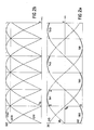
- FIG. 2a represents the variation over a period T, as a function of time, of the reference currents I R1 to I R3 which must pass in the windings of a three-phase synchronous motor at constant speed and torque. It is noted that these three simusoidal currents, on each sixth of period T / 6, are such that only one does not have the same sign as the others and it is precisely the one whose amplitude in absolute value
- the maximum switching losses of the switch are no longer located at the point where the current is maximum in the phase, but for a current I M ⁇ ⁇ 3 / 2 (point A).
- the current gradient at this point is large, which minimizes the duration of energy dissipation during the rotation of the motor.
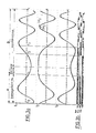
- FIG. 3a are shown the variations as a function of time of the currents I M passing through the windings of a three-phase synchronous motor controlled according to the strategy of the invention during a braking and then acceleration cycle and in FIG. 3b are shown the conduction signals CHi and CBi, i varying from 1 to 3, high and low transistors of a three-phase inverter, respectively for the windings L1 to L3.
- part 1 of the diagram between the instants T0 and T1 the control of the switches is done according to a conventional three-phase strategy, the validation criteria of the control process not being respected, that is to say that alternatively all the switches drive and are blocked.
- the strategy according to the invention is applied, that is to say that the high TH i or low TB i switches associated with the winding L i where the maximum current flows are kept in conduction.
- the high switch TH2 is in conduction and the low switch TB2 is blocked; between the instants T2 and T3, the current I M3 is maximum in absolute value but of negative sign so that the high switch T H3 is blocked and the low switch TB3 conducts.
- FIG. 4 shows a particular but non-limiting embodiment of a control device according to the invention, always in the case of a three-phase inverter.
- the device comprises a processor 11, equipped with an analog-to-digital converter 10, fulfilling both the function of detecting the winding of the motor in which the maximum current flows and the function of validating the process of ordered.
- the analog-digital converter 10 connected to the input of the processor 11, receives on the one hand the values of the currents flowing in at least two phases of the motor, or else the angular position of the rotor given by a position sensor (12) and on the other hand the value of the current setpoint I applied to the motor and the value of the speed of rotation of the rotor.
- This converter transforms this analog data into binary information which it transmits to the processor. The latter then transmits the conduction signals to the switches according to the control method according to the invention.
Landscapes
- Engineering & Computer Science (AREA)
- Power Engineering (AREA)
- Control Of Motors That Do Not Use Commutators (AREA)
Applications Claiming Priority (2)
| Application Number | Priority Date | Filing Date | Title |
|---|---|---|---|
| FR8603420 | 1986-03-11 | ||
| FR8603420A FR2595885B1 (fr) | 1986-03-11 | 1986-03-11 | Procede de commande d'un onduleur a modulation de largeur par impulsions associe a un moteur a n phases et dispositif de mise en oeuvre du procede |
Publications (2)
| Publication Number | Publication Date |
|---|---|
| EP0241326A1 true EP0241326A1 (de) | 1987-10-14 |
| EP0241326B1 EP0241326B1 (de) | 1992-01-15 |
Family
ID=9332986
Family Applications (1)
| Application Number | Title | Priority Date | Filing Date |
|---|---|---|---|
| EP19870400518 Expired - Lifetime EP0241326B1 (de) | 1986-03-11 | 1987-03-10 | Verfahren zur Regelung eines Pulsbreitenmodulierten Wechselrichters mit n-phasigem Motor und Gerät zur Realisierung des Verfahrens |
Country Status (3)
| Country | Link |
|---|---|
| EP (1) | EP0241326B1 (de) |
| DE (1) | DE3775965D1 (de) |
| FR (1) | FR2595885B1 (de) |
Cited By (2)
| Publication number | Priority date | Publication date | Assignee | Title |
|---|---|---|---|---|
| EP0525999A3 (en) * | 1991-07-11 | 1995-11-02 | Sgs Thomson Microelectronics | Synchronous rectification method for reducing power dissipation in motor drivers in pwm mode |
| WO2000069060A1 (en) * | 1999-05-06 | 2000-11-16 | Emerson Electric Co. | Device and method for generating three-phase sine waves using two pulse-width modulators |
Families Citing this family (1)
| Publication number | Priority date | Publication date | Assignee | Title |
|---|---|---|---|---|
| HU195599B (en) * | 1986-11-20 | 1988-05-30 | Villamos Ipari Kutato Intezet | Method for controlling and regulating multiphase inverters of follow-up control, and circuit arrangement realized by the application of the method for three-phase inverters of follow-up control |
Citations (3)
| Publication number | Priority date | Publication date | Assignee | Title |
|---|---|---|---|---|
| US4002958A (en) * | 1973-12-28 | 1977-01-11 | Mitsubishi Denki Kabushiki Kaisha | AC output power control system |
| EP0102614A2 (de) * | 1982-09-03 | 1984-03-14 | Hitachi, Ltd. | Verfahren und Gerät zur Regelung eines pulsbreitenmodulierten Wechselrichters |
| US4467262A (en) * | 1980-03-24 | 1984-08-21 | The Charles Stark Draper Laboratory, Inc. | Polyphase motor drive system with balanced modulation |
-
1986
- 1986-03-11 FR FR8603420A patent/FR2595885B1/fr not_active Expired
-
1987
- 1987-03-10 DE DE8787400518T patent/DE3775965D1/de not_active Expired - Lifetime
- 1987-03-10 EP EP19870400518 patent/EP0241326B1/de not_active Expired - Lifetime
Patent Citations (3)
| Publication number | Priority date | Publication date | Assignee | Title |
|---|---|---|---|---|
| US4002958A (en) * | 1973-12-28 | 1977-01-11 | Mitsubishi Denki Kabushiki Kaisha | AC output power control system |
| US4467262A (en) * | 1980-03-24 | 1984-08-21 | The Charles Stark Draper Laboratory, Inc. | Polyphase motor drive system with balanced modulation |
| EP0102614A2 (de) * | 1982-09-03 | 1984-03-14 | Hitachi, Ltd. | Verfahren und Gerät zur Regelung eines pulsbreitenmodulierten Wechselrichters |
Cited By (2)
| Publication number | Priority date | Publication date | Assignee | Title |
|---|---|---|---|---|
| EP0525999A3 (en) * | 1991-07-11 | 1995-11-02 | Sgs Thomson Microelectronics | Synchronous rectification method for reducing power dissipation in motor drivers in pwm mode |
| WO2000069060A1 (en) * | 1999-05-06 | 2000-11-16 | Emerson Electric Co. | Device and method for generating three-phase sine waves using two pulse-width modulators |
Also Published As
| Publication number | Publication date |
|---|---|
| FR2595885B1 (fr) | 1988-06-10 |
| EP0241326B1 (de) | 1992-01-15 |
| DE3775965D1 (de) | 1992-02-27 |
| FR2595885A1 (fr) | 1987-09-18 |
Similar Documents
| Publication | Publication Date | Title |
|---|---|---|
| EP2294688B1 (de) | Verfahren zur bestimmung der induktanzen einer permanentmagnet-synchronmaschine | |
| FR2532490A1 (fr) | Dispositif de commande d'un moteur a courant continu sans balais | |
| EP0798847B1 (de) | Frequenz-Umformer für Wechselstrommotor | |
| EP1020019B1 (de) | Gerät und verfahren zur steuerung eines synchronmotors mit permanentmagnet | |
| FR2458940A1 (fr) | Dispositif d'attaque de moteur a courant continu sans balai | |
| FR2855677A1 (fr) | Circuit de commande a modulation en largeur d'impulsions pour machine electrique multi mode et machine electrique multi mode equipee d'un tel circuit de commande | |
| EP1974455B1 (de) | Vorrichtung zur steuerung einer polyphasen-rotationsmaschine | |
| FR2996075A1 (fr) | Procede pour determiner les courants de phase d'une machine electrique avec un redresseur | |
| EP3014758B1 (de) | Motorsteuerungsvorrichtung | |
| EP0658971B1 (de) | System zur Steuerung der Stromversorgung eines Asynchronmotors | |
| EP1398869B1 (de) | Prozess und Rechner zur Bestimmung des Drehwinkels eines Rotors in Ruhelage, Steuereinheit und System unter Verwendung des Rechners | |
| EP0834983A2 (de) | Anordnung zur Strommessung in einem Wechselrichter | |
| FR2999038A1 (fr) | Installation de commande et procede pour determiner l'angle du rotor d'une machine synchrone | |
| EP0241326B1 (de) | Verfahren zur Regelung eines Pulsbreitenmodulierten Wechselrichters mit n-phasigem Motor und Gerät zur Realisierung des Verfahrens | |
| EP0449687B1 (de) | Regelprozess eines selbstgeführten Synchronmotors und Vorrichtung zu seiner Verwendung | |
| FR2923331A1 (fr) | Appareil electrique rotatif pour automobile | |
| EP0433219B1 (de) | Regelkreis für kollektorlosen elektrischen Motor | |
| EP0173595A1 (de) | Verfahren und Vorrichtung zur Bestimmung eines Synchronisationssignales aus den Spannungsphasen eines Stromnetzes | |
| FR2855679A1 (fr) | Procede et systeme de regulation du couple electromagnetique instantane, et support d'enregistrement pour la mise en oeuvre du procede | |
| EP3167543B1 (de) | Verfahren zur erzeugung von steuersignalen zur verwaltung des betriebs eines synchronmotors, steuerungsvorrichtung und aktuator | |
| EP3766169A1 (de) | Verfahren zur steuerung eines umrichters | |
| FR2487141A1 (fr) | Appareil de commande pour moteurs asynchrones | |
| FR3073993B1 (fr) | Procede de commande d'un onduleur triphase | |
| WO2018130793A1 (fr) | Systeme de commande pour une machine electrique tournante | |
| FR2697697A1 (fr) | Procédé pour alimenter un moteur à reluctance variable et dispositif pour sa mise en Óoeuvre. |
Legal Events
| Date | Code | Title | Description |
|---|---|---|---|
| PUAI | Public reference made under article 153(3) epc to a published international application that has entered the european phase |
Free format text: ORIGINAL CODE: 0009012 |
|
| 17P | Request for examination filed |
Effective date: 19870312 |
|
| AK | Designated contracting states |
Kind code of ref document: A1 Designated state(s): CH DE GB IT LI SE |
|
| RAP1 | Party data changed (applicant data changed or rights of an application transferred) |
Owner name: LA TELEMECANIQUE ELECTRIQUE |
|
| 17Q | First examination report despatched |
Effective date: 19890719 |
|
| RAP1 | Party data changed (applicant data changed or rights of an application transferred) |
Owner name: TELEMECANIQUE |
|
| GRAA | (expected) grant |
Free format text: ORIGINAL CODE: 0009210 |
|
| AK | Designated contracting states |
Kind code of ref document: B1 Designated state(s): CH DE GB IT LI SE |
|
| PG25 | Lapsed in a contracting state [announced via postgrant information from national office to epo] |
Ref country code: SE Effective date: 19920115 |
|
| ITF | It: translation for a ep patent filed | ||
| GBT | Gb: translation of ep patent filed (gb section 77(6)(a)/1977) | ||
| REF | Corresponds to: |
Ref document number: 3775965 Country of ref document: DE Date of ref document: 19920227 |
|
| ITTA | It: last paid annual fee | ||
| PG25 | Lapsed in a contracting state [announced via postgrant information from national office to epo] |
Ref country code: LI Effective date: 19920331 Ref country code: CH Effective date: 19920331 |
|
| PLBE | No opposition filed within time limit |
Free format text: ORIGINAL CODE: 0009261 |
|
| STAA | Information on the status of an ep patent application or granted ep patent |
Free format text: STATUS: NO OPPOSITION FILED WITHIN TIME LIMIT |
|
| REG | Reference to a national code |
Ref country code: CH Ref legal event code: PL |
|
| 26N | No opposition filed | ||
| PGFP | Annual fee paid to national office [announced via postgrant information from national office to epo] |
Ref country code: GB Payment date: 19960305 Year of fee payment: 10 |
|
| PGFP | Annual fee paid to national office [announced via postgrant information from national office to epo] |
Ref country code: DE Payment date: 19960318 Year of fee payment: 10 |
|
| PG25 | Lapsed in a contracting state [announced via postgrant information from national office to epo] |
Ref country code: GB Effective date: 19970310 |
|
| GBPC | Gb: european patent ceased through non-payment of renewal fee |
Effective date: 19970310 |
|
| PG25 | Lapsed in a contracting state [announced via postgrant information from national office to epo] |
Ref country code: DE Effective date: 19971202 |
|
| PG25 | Lapsed in a contracting state [announced via postgrant information from national office to epo] |
Ref country code: IT Free format text: LAPSE BECAUSE OF NON-PAYMENT OF DUE FEES;WARNING: LAPSES OF ITALIAN PATENTS WITH EFFECTIVE DATE BEFORE 2007 MAY HAVE OCCURRED AT ANY TIME BEFORE 2007. THE CORRECT EFFECTIVE DATE MAY BE DIFFERENT FROM THE ONE RECORDED. Effective date: 20050310 |