EP0241348A1 - Verfahren und Vorrichtung zum Schmelzen von Paraffinkristallen in Brennstoffen - Google Patents
Verfahren und Vorrichtung zum Schmelzen von Paraffinkristallen in Brennstoffen Download PDFInfo
- Publication number
- EP0241348A1 EP0241348A1 EP87400676A EP87400676A EP0241348A1 EP 0241348 A1 EP0241348 A1 EP 0241348A1 EP 87400676 A EP87400676 A EP 87400676A EP 87400676 A EP87400676 A EP 87400676A EP 0241348 A1 EP0241348 A1 EP 0241348A1
- Authority
- EP
- European Patent Office
- Prior art keywords
- fuel
- heating
- temperature
- filter
- heating chamber
- Prior art date
- Legal status (The legal status is an assumption and is not a legal conclusion. Google has not performed a legal analysis and makes no representation as to the accuracy of the status listed.)
- Withdrawn
Links
- 239000000446 fuel Substances 0.000 title claims abstract description 51
- 238000000034 method Methods 0.000 title claims abstract description 11
- 239000013078 crystal Substances 0.000 title abstract description 10
- 239000012188 paraffin wax Substances 0.000 title abstract description 7
- 230000008018 melting Effects 0.000 title description 6
- 238000002844 melting Methods 0.000 title description 6
- 238000010438 heat treatment Methods 0.000 claims abstract description 111
- 238000009434 installation Methods 0.000 claims abstract description 10
- 238000011144 upstream manufacturing Methods 0.000 claims abstract description 7
- 239000011248 coating agent Substances 0.000 claims abstract description 6
- 238000000576 coating method Methods 0.000 claims abstract description 6
- 239000004065 semiconductor Substances 0.000 claims abstract description 3
- 238000011045 prefiltration Methods 0.000 claims description 17
- 238000005485 electric heating Methods 0.000 claims description 7
- 239000004020 conductor Substances 0.000 claims description 6
- 230000000694 effects Effects 0.000 claims description 5
- 238000001914 filtration Methods 0.000 claims description 5
- 239000000463 material Substances 0.000 claims description 5
- PNEYBMLMFCGWSK-UHFFFAOYSA-N aluminium oxide Inorganic materials [O-2].[O-2].[O-2].[Al+3].[Al+3] PNEYBMLMFCGWSK-UHFFFAOYSA-N 0.000 claims description 3
- 229910052799 carbon Inorganic materials 0.000 claims description 3
- 230000006835 compression Effects 0.000 claims description 3
- 238000007906 compression Methods 0.000 claims description 3
- 229910052751 metal Inorganic materials 0.000 claims description 3
- 239000002184 metal Substances 0.000 claims description 3
- SWELZOZIOHGSPA-UHFFFAOYSA-N palladium silver Chemical compound [Pd].[Ag] SWELZOZIOHGSPA-UHFFFAOYSA-N 0.000 claims description 3
- 239000007921 spray Substances 0.000 claims description 3
- 230000008021 deposition Effects 0.000 claims description 2
- 239000012777 electrically insulating material Substances 0.000 claims description 2
- 230000005611 electricity Effects 0.000 claims description 2
- 239000011521 glass Substances 0.000 claims description 2
- GNLCAVBZUNZENF-UHFFFAOYSA-N platinum silver Chemical compound [Ag].[Ag].[Ag].[Pt] GNLCAVBZUNZENF-UHFFFAOYSA-N 0.000 claims description 2
- 230000001105 regulatory effect Effects 0.000 claims description 2
- 229920005989 resin Polymers 0.000 claims description 2
- 239000011347 resin Substances 0.000 claims description 2
- 230000000630 rising effect Effects 0.000 claims description 2
- 238000007789 sealing Methods 0.000 claims description 2
- 239000004593 Epoxy Substances 0.000 claims 1
- 230000010259 detection of temperature stimulus Effects 0.000 claims 1
- 238000001514 detection method Methods 0.000 abstract description 2
- 239000002283 diesel fuel Substances 0.000 description 21
- 239000010771 distillate fuel oil Substances 0.000 description 20
- 239000000523 sample Substances 0.000 description 10
- 238000010586 diagram Methods 0.000 description 5
- 239000000203 mixture Substances 0.000 description 4
- 239000003990 capacitor Substances 0.000 description 2
- 125000004432 carbon atom Chemical group C* 0.000 description 2
- 238000002425 crystallisation Methods 0.000 description 2
- 230000008025 crystallization Effects 0.000 description 2
- 238000009826 distribution Methods 0.000 description 2
- 239000003822 epoxy resin Substances 0.000 description 2
- 229910001234 light alloy Inorganic materials 0.000 description 2
- 239000013081 microcrystal Substances 0.000 description 2
- 235000013379 molasses Nutrition 0.000 description 2
- 239000003921 oil Substances 0.000 description 2
- 229920000647 polyepoxide Polymers 0.000 description 2
- 239000011148 porous material Substances 0.000 description 2
- 239000002244 precipitate Substances 0.000 description 2
- 238000007650 screen-printing Methods 0.000 description 2
- 229920002302 Nylon 6,6 Polymers 0.000 description 1
- XUIMIQQOPSSXEZ-UHFFFAOYSA-N Silicon Chemical compound [Si] XUIMIQQOPSSXEZ-UHFFFAOYSA-N 0.000 description 1
- 239000000654 additive Substances 0.000 description 1
- 229910052782 aluminium Inorganic materials 0.000 description 1
- XAGFODPZIPBFFR-UHFFFAOYSA-N aluminium Chemical compound [Al] XAGFODPZIPBFFR-UHFFFAOYSA-N 0.000 description 1
- 125000004429 atom Chemical group 0.000 description 1
- 238000010009 beating Methods 0.000 description 1
- 230000001276 controlling effect Effects 0.000 description 1
- 238000005553 drilling Methods 0.000 description 1
- 238000010292 electrical insulation Methods 0.000 description 1
- 238000005516 engineering process Methods 0.000 description 1
- 230000005284 excitation Effects 0.000 description 1
- 239000002360 explosive Substances 0.000 description 1
- 239000000295 fuel oil Substances 0.000 description 1
- 230000009931 harmful effect Effects 0.000 description 1
- 238000009413 insulation Methods 0.000 description 1
- 238000003754 machining Methods 0.000 description 1
- 239000012528 membrane Substances 0.000 description 1
- 238000000465 moulding Methods 0.000 description 1
- 230000003647 oxidation Effects 0.000 description 1
- 238000007254 oxidation reaction Methods 0.000 description 1
- 239000004033 plastic Substances 0.000 description 1
- 238000001556 precipitation Methods 0.000 description 1
- 239000000047 product Substances 0.000 description 1
- 238000007670 refining Methods 0.000 description 1
- 238000003303 reheating Methods 0.000 description 1
- 238000010079 rubber tapping Methods 0.000 description 1
- 229920006395 saturated elastomer Polymers 0.000 description 1
- 230000035939 shock Effects 0.000 description 1
- 229910052710 silicon Inorganic materials 0.000 description 1
- 239000010703 silicon Substances 0.000 description 1
- 239000007787 solid Substances 0.000 description 1
- 230000009897 systematic effect Effects 0.000 description 1
- 238000010257 thawing Methods 0.000 description 1
- 238000012795 verification Methods 0.000 description 1
- 238000004017 vitrification Methods 0.000 description 1
- 238000003466 welding Methods 0.000 description 1
Images
Classifications
-
- F—MECHANICAL ENGINEERING; LIGHTING; HEATING; WEAPONS; BLASTING
- F02—COMBUSTION ENGINES; HOT-GAS OR COMBUSTION-PRODUCT ENGINE PLANTS
- F02M—SUPPLYING COMBUSTION ENGINES IN GENERAL WITH COMBUSTIBLE MIXTURES OR CONSTITUENTS THEREOF
- F02M31/00—Apparatus for thermally treating combustion-air, fuel, or fuel-air mixture
- F02M31/02—Apparatus for thermally treating combustion-air, fuel, or fuel-air mixture for heating
- F02M31/12—Apparatus for thermally treating combustion-air, fuel, or fuel-air mixture for heating electrically
- F02M31/125—Fuel
-
- F—MECHANICAL ENGINEERING; LIGHTING; HEATING; WEAPONS; BLASTING
- F02—COMBUSTION ENGINES; HOT-GAS OR COMBUSTION-PRODUCT ENGINE PLANTS
- F02B—INTERNAL-COMBUSTION PISTON ENGINES; COMBUSTION ENGINES IN GENERAL
- F02B3/00—Engines characterised by air compression and subsequent fuel addition
- F02B3/06—Engines characterised by air compression and subsequent fuel addition with compression ignition
-
- Y—GENERAL TAGGING OF NEW TECHNOLOGICAL DEVELOPMENTS; GENERAL TAGGING OF CROSS-SECTIONAL TECHNOLOGIES SPANNING OVER SEVERAL SECTIONS OF THE IPC; TECHNICAL SUBJECTS COVERED BY FORMER USPC CROSS-REFERENCE ART COLLECTIONS [XRACs] AND DIGESTS
- Y02—TECHNOLOGIES OR APPLICATIONS FOR MITIGATION OR ADAPTATION AGAINST CLIMATE CHANGE
- Y02T—CLIMATE CHANGE MITIGATION TECHNOLOGIES RELATED TO TRANSPORTATION
- Y02T10/00—Road transport of goods or passengers
- Y02T10/10—Internal combustion engine [ICE] based vehicles
- Y02T10/12—Improving ICE efficiencies
Definitions
- the present invention relates to a device for defrosting the crystals of paraffins included in diesel fuels and light fuel oils, crystals which precipitate on the external surface of the filter elements of compression ignition engines or other installations, for example installations heating, this device comprising one or more electrical resistors which, in applications to vehicles with diesel engines, are powered by the battery or the alternator.
- An effective de-icing device must therefore include a heating surface approaching 70 ° C. However, for there to be no loss of power or damage to the engines, it is necessary to avoid, at the end of the preheating period, before starting the engine, heating the diesel fuel or light fuel oil beyond 40 ° C. It is therefore necessary to dissociate the temperature regulation of the surface of the heating resistors from that of the temperature of the flow of diesel fuel or light fuel oil. It should also be noted that, as far as vehicle clearance is concerned, in their series design, they do not have a sufficient electric source to raise the average temperature of the flow above the melting point of the vehicles. large paraffin crystals.
- de-icing is understood to mean the melting of the paraffin crystals and not only a reheating delaying the crystallization of the paraffins.
- the present invention recommends, and this is its first object, a process for de-icing fuels containing paraffins, when these, under the effect of cold, obstruct the filter element of the filter and of the prefilter when it exists, placed on the supply circuit of a compression ignition engine or of a heating installation, a pump being located downstream of the filter to suck the fuel coming from a tank, process according to which there is a heat source in a heating chamber, which is placed upstream and near said filter element and which will be traversed by the fuel flow, this process being characterized in that a heating chamber is used of small volume compared to the volume of the filter or the prefilter and a source of heat regulated at approximately 70 ° C, which will project in the filtering element, at the starting of the pump, the few cubic centimeters of fuel, contained in the c heating chamber and preheated to around 70 ° C, which will then project into the filter element very hot streams of fuel included in the flow thereof, whose average temperature remains below 40 °
- the ratio of the volume of the heating chamber to that of the filter is of the order of 1 to 10 to 1 to 20 according to the present invention.
- This device which comprises a heating chamber in which is housed a heating element, this chamber intended to be traversed by the fuel being disposed upstream and near the filter element of the filter and of the prefilter when it exists, placed on the supply circuit of said motor or of said heating installation, is characterized in that the heating chamber is of small volume relative to the volume of the filter or of the prefilter, in that the heating element consists of at least one electrical resistance in the form of an extra-flat circuit on a rigid support plate, in that thermal regulation means are added to the heating element to prevent the fuel temperature from rising above approximately 70 ° C, and in that the heating element is protected from direct contact with the fuel by an electrically insulating coating.
- the support plate is made of a material which does not conduct electricity (alumina, epoxy resin, enameled sheet, pre-oxidized metal, etc.).
- the extra-flat circuit can be a screen-printed metallic deposit or by decal or by projection.
- the electrically insulating coating can be a vitrification, a spray of resin, an oxidation of the metal forming the resistance.
- the heating chamber can be either an independent heating body placed just before the entry of the filter and / or the pre-filter if it exists, or an intermediate element placed between the filter and / or prefilter head 'and the 'filter element (filter cartridge); it can also be formed by molding or drilling in the fuel inlet circuit in the head of the filter, and / or of the prefilter if necessary.
- filter used in the description should be considered to include the filter and the prefilter.
- the present invention therefore uses, among other things, printed circuits. It is used as support a plate with an approximate thickness of one to two millimeters of electrically insulating material, as mentioned above, on one side of which is for example printed a metallic circuit in palladium-silver or platinum-silver or the like , formed by screen printing or by vacuum projection.
- the shape of this plate is a rectangle of about 15 x 100 mm and the design of the electrical resistance can be varied: either an elongated U, or a U with zigzag branches allowing to increase its length developed on a small plate, or any other design allowing to control on the surface of the plate the proper distribution of the electrical power released by the resistance.
- the electrical resistance and the surface of the plate are chosen such that the average power of the heating element does not exceed 10 watts / cm s + 5% on each of its faces. This power per cm 2 has been calculated so that the temperature of the surface of the resistor does not exceed 70 ° C ⁇ 5% when the heating element is immersed in a flow of diesel fuel or light fuel oil, itself having a inlet temperature 15 ° C or lower of the device, said flow corresponding to normal flow rates of diesel engines as a function of their power.
- the vertical arrangement of the heating pad in the heating chamber and the shape of the latter channel the flow along a U-shaped path, so that it licks the surface of the pad all along its two faces, so that the flow of diesel fuel or light fuel oil has the longest possible contact time with the heating element (hence a very high heat exchange coefficient) and leaves, just at the end of the heating chamber, with a turbulent flow, so that there is a great disparity in the temperatures of the instantaneous flow both in its volume and in time.
- the heating chamber is located very close to the filter element, the latter is struck at least intermittently by threads or jets having very variable temperature distributions, some of which exceed the melting temperature. heavier paraffins, so that the filtration surfaces are actually washed by melting the most difficult to melt crystals.
- Such resistance in a printed circuit also has the advantage of an extremely rapid rise in temperature of the exchange surface, much greater than that of heating rods and, moreover, it does not does not have the inertia of these, which makes it possible to reduce at start-up the preheating time.
- a thermal sensor or sensor for example of the CTN type, is installed far enough from the heating circuit to minimize its influence, and on the side of the plate where the fuel leaves the heating chamber to measure the temperature in this zone.
- the nature of the sensor is preferably chosen from among the semiconductors working on a low amperage current, this sensor, depending on its type, can either be fixed on the end of the support of the heating element on the side of the fuel outlet from the heating chamber, either be fixed on an independent support, placed in the fuel flow on the side of its outlet from the heating chamber.
- the resistance of which varies according to the temperature a CTN with a negative temperature coefficient, or a PTC with a positive temperature coefficient, or a silicon sensor CT P , or a transistor is preferably chosen. .
- the thermal sensor and its supply circuit are electrically isolated by any suitable means, in order to ensure perfect insulation of the electrified elements from the flow of diesel fuel or light fuel oil, in which the heating pad is bathed, which is very important in terms of safety and essential in the event of application of the device to vehicles transporting dangerous products or to installations in an explosive atmosphere.
- This arrangement avoids the drawback of bare electrical contacts in light fuels or fuel oils, made partially conductive by the presence of moisture and as described in certain aforementioned patents (aforementioned EP 0051936 and 155839).
- the thermal probe is connected to a solid-state bridge which controls the resistor supply relay with a current of 80 to 160 milliamps.
- the temperature regulation of the flow of diesel fuel or light fuel oil is sometimes from 65 to 70 ° C, sometimes from 35 to 40 ° C, depending on whether the device is connected to a second so-called external temperature sensor, which does not put the device under tension only if the outside temperature or that of the flow of diesel fuel or light fuel oil upstream of the device does not exceed 10 ° C.
- This external probe can be either an electronic device similar to the thermal regulation system of the resistance, or a thermoswitch with a blistering membrane, with an engagement at the drop in temperature at 5 ° C and a trigger at the rise in temperature at 10 ° C .
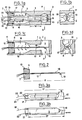
- FIGS 1a, 1b, 1c and 1d are schematic sectional views of the heating chamber, in its heating body version located at the inlet of the filter or the prefilter not shown.
- a body 1 is made of light alloy so that the fatigue forces due to vibrations do not require the presence of a fixing system on rigid elements of other mechanical parts of the vehicle.
- This body is in principle cut from a light alloy bar with a square section of 30 mm side.
- At the end 2 of the body are drilled and tapped, to different sizes depending on the diameter of the prefilter or filter inlet openings, openings 3 and 4 through which diesel fuel or light fuel oil enters and leaves the heating body.
- a lug 12 of the plug 7 is inserted in a notch 13 previously machined in the body 1 or vice versa.
- the body 1 has a reduced diameter along the length 14 to provide an approximately U-shaped path of the fuel. This is also shown on the sections AB and CD, and the machining tolerances of the interior of the heating body are determined so that this is so.
- the heating element 6 ends at approximately 1 mm from the internal surface 15 of the body 1. The flow of diesel fuel or light fuel oil is therefore forced to go along the two faces of the heating element 6 passing from one side to the other, thanks to the recess 16 hollowed out in the body 1.
- the unencrypted arrows show the direction of the flow.
- Defrosters with larger heating chambers and larger size and power resistors may be produced for higher power motors or installations. It is also possible to design defiggers with several heating chambers installed in series or in parallel depending on the case and each comprising heating and control members similar to those presently described.
- FIG. 2 represents the heating element 6. It consists, in addition to the fixing plug 7 already described, of a rigid plate for example of alumina or of epoxy resin 17 on which is deposited for example by screen printing, on a only on the face, a mixture of palladium-silver constituting the actual resistance 18.
- a thermal sensor 19 On the other side of the plate, at its end devoid of a heating circuit, is a thermal sensor 19 and its two conductors 32, 33 also screen printed, in the case of a probe which can be fixed on the plate, that is to say which will measure the temperature of the fuel (and not that of the plate). More generally, the thermal probe will be fixed on an independent support mounted in the plug 7.
- Figures 3a and 3b show the wafer 17 and its various elements.
- the shape of the deposit, for example screen-printed, for the heating circuit 18 can be variable. It is here represented (FIG. 3a) by a double U which does not extend to the end 20 of the plate to allow various solutions concerning the entry and exit of diesel fuel or light fuel oil. This deposition is preferably carried out on one side only, for cost reasons and to allow an easier arrangement of the feeler or thermal sensor 19 on the other face (FIG. 3b).
- the plate has at its end 21 two large deposits 22 allowing the welding of the electrical supply wires (23 and 24).
- the thermal sensor 19 is a thermistor whose variation in resistivity is exploited as a function of the temperature; it constitutes one of the branches of a Wheatstone bridge and the entire regulation scheme is described below with reference to FIG. 5.
- the present scheme has chosen, in the current state of the art, a sensor whose temperature coefficient is negative, namely a CTN having approximate characteristics, 47,000 ohms at 25 ° C, 8,000 ohms at 65 ° C, 6800 ohms at 70 ° C. It should be noted that its non-linearity is not a drawback for the present application.
- the whole of the heating circuit 18 and of the thermal probe 19 is, for example, vitrified recto / verso over the length 27 comprising the active part plus a part reentrant in the plug 7. This allows perfect electrical insulation between the electric circuits and the diesel fuel or light fuel oil.
- the heating circuit 18 is connected to the relay 28 (FIG. 4) by the conductor 23 and to the negative terminal 52 of the battery 29 (FIG. 4) by the conductor 24.
- the thermal probe 19 is connected to the terminals 30 and 31 of the bridge. Wheatstone of the thermal regulation printed circuit 26 by the conductors 32 and 33.
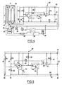
- FIG. 4 shows the general electrical diagram of the device.
- this diagram includes a battery 29, the + 34 terminal of which supplies the excitation circuit of the relay 28 and the connected terminal 36 at terminal 33 of the heating element 6, via the general contact 35 of the vehicle or installation and by an external probe 37, the contact of which is closed at a drop in temperature to around 5 ° C and reopens when the temperature rises to around 10 ° C.
- This hysteresis is essential to prevent the system from stopping too early in the event of a rapid rise in the ambient temperature while the diesel fuel or light fuel oil is still frozen in the tank.
- This probe can be either external or inserted in the diesel fuel or light fuel line upstream of the heating element.
- the battery terminal + 34 also supplies, via a fuse 38 and of the power circuit of the relay 28, the input terminal 23 of the heating element 6, the operation lamp 39 and the terminal 40 of the thermal regulation circuit 26.
- the terminal - 52 of the battery 29 is connected to the return terminal 24 of the heating element 6, that of the indicator 39 and terminal 41 of the thermal regulation circuit 26.
- FIG. 5 represents the thermal regulation printed circuit 26.
- This circuit is either located outside the heating element 6, either applied on its back, or integrated in the molded plug 7, and the few calories released by this circuit secondary could not be considered as taking an active part in the heating of diesel fuel or light fuel oil, especially in the version where only the thermal sensor 19 is embedded therein.
- This thermal regulation circuit 26 comprises different electronic components working with low currents of between 100 and 200 milliamps.
- the temperature threshold detection circuit is based on the use of a Wheatstone bridge followed by an analog comparator, the change of state of the comparator occurring at equilibrium of the bridge; the hysteresis effect, so important for the overall good functioning of the device, is obtained by the presence of a resistor in parallel on a branch (resistor R4-45); this resistance ensures a hysteresis between the cut-off and reset temperatures, hysteresis which is necessary to suppress the beats in the electrical circuits and thus reduce the frequency of the subtransient currents.
- a circuit means that the regulation is insensitive to the supply voltage of the Wheatstone bridge, whether under 12 or 24 V battery, or under alternator.
- the Wheatstone bridge has resistors R1-42, R2-43, R3-44, which are identical, with an R value substantially equal to the ohmic value of the CTN 19 thermal probe at 65 ° C (if the maximum temperature of diesel fuel or light fuel oil is to be adjusted to this value). Any other temperature, for example 40 ° C, would lead to other resistance values, but the diagram would be identical.
- the choice of the value in ohms of the resistances of the Wheatstone bridge determines the cut-out temperature of the heating element.
- the resistance R 4-45 will have a value 4 times greater than the value R; R must be between 5 and 10 Kohms, which also conditions the choice of the CTN of the CTN 19 thermal probe.
- a CIL-46 linear circuit is then used as a comparator in a micro-box (preferably a differential amplifier with discrete transistors).
- a micro-box preferably a differential amplifier with discrete transistors.
- a Motorola SOIC comparator is used.
- Relay 28 is controlled by an integrated Darlington transistor TR-25 comprising two successive transistors, one low-power bipolar used in saturated mode blocked in a common transmitter assembly, the other ensuring saturation.
- this Darlington transistor we could use Mosfet transistor technology.
- the base current is equal to 1 / 10th of the collector current.
- the resistors R8-48 and R9-49 have values between 5 and 10 Kohms. Resistor R9-49, in parallel with the relay coil, is only intended to allow verification of the proper functioning of the system, the relay being disconnected. Resistor R8-48 supplies the basic current of transistor 25, when the output of the comparator is in the high state.
- a set D1-47 of two diodes is placed in parallel in the circuit.
- the capacitor C1-50 is introduced into the circuit, the position of which must be as close as possible to the output of the comparator 46. If C1-50 was too far away, this Cl-50 capacitor would have no effect.
- a D2-51 diode has been introduced to protect the printed circuit against any connection error; it is placed in series between the control circuit and the earthing of the heating resistor. Other solid state devices can complete the thermal regulation circuit to increase reliability and precision.
- the resistor R4-45 which reduces the frequency of the subtransient currents as mentioned above, it therefore ensures a normal service life of the electric heating circuit and the electric thermal regulation circuit, and in particular of the relay 28 for supplying the heating element 6, transistors 25 controlling this relay, the heating resistor 18, the diodes 47 provided to reduce the harmful effects of said subtransient currents and the diode 51 provided to protect the printed circuit against a connection error.
- the electrical circuit is such that the power supply (that of the heating resistor), is made by two independent wires (connections 23 and 24), one of which is not necessarily connected to ground, and that the power supply to the low power control circuit is also provided by two other independent wires (connections 36 and 41), one of which is not necessarily connected to ground.
Landscapes
- Engineering & Computer Science (AREA)
- Chemical & Material Sciences (AREA)
- Combustion & Propulsion (AREA)
- Mechanical Engineering (AREA)
- General Engineering & Computer Science (AREA)
- Combined Controls Of Internal Combustion Engines (AREA)
- Filtration Of Liquid (AREA)
Applications Claiming Priority (2)
| Application Number | Priority Date | Filing Date | Title |
|---|---|---|---|
| FR8604917A FR2596811B1 (fr) | 1986-04-07 | 1986-04-07 | Procede et dispositif de defigeage des carburants |
| FR8604917 | 1986-04-07 |
Publications (1)
| Publication Number | Publication Date |
|---|---|
| EP0241348A1 true EP0241348A1 (de) | 1987-10-14 |
Family
ID=9333958
Family Applications (1)
| Application Number | Title | Priority Date | Filing Date |
|---|---|---|---|
| EP87400676A Withdrawn EP0241348A1 (de) | 1986-04-07 | 1987-03-26 | Verfahren und Vorrichtung zum Schmelzen von Paraffinkristallen in Brennstoffen |
Country Status (3)
| Country | Link |
|---|---|
| US (1) | US4793317A (de) |
| EP (1) | EP0241348A1 (de) |
| FR (1) | FR2596811B1 (de) |
Families Citing this family (7)
| Publication number | Priority date | Publication date | Assignee | Title |
|---|---|---|---|---|
| US4886032A (en) * | 1988-11-22 | 1989-12-12 | Chrysler Motors Corporation | Fuel injector heating method |
| DE4314283C2 (de) * | 1993-04-30 | 1995-04-13 | Freudenberg Carl Fa | Heizmodul für eine Verbrennungskraftmaschine |
| US6081109A (en) * | 1997-11-07 | 2000-06-27 | Xantech Corporation | Current sensing device |
| US20040103875A1 (en) * | 2002-12-03 | 2004-06-03 | Simon Aaron Joseph | Method and apparatus for suppressing diesel engine emissions |
| ITTO20080271A1 (it) * | 2008-04-08 | 2009-10-09 | Eltek Spa | "dispositivo di riscaldamento per condotti di alimentazione del combustibile, condotto di alimentazione del combustibile e motore a combustione" |
| BR102020026406A2 (pt) * | 2020-12-22 | 2022-07-05 | Robert Bosch Limitada | Dispositivo para aquecimento de combustível |
| CN112664366B (zh) * | 2020-12-24 | 2022-07-12 | 奇瑞汽车股份有限公司 | 油轨加热系统、方法及车辆 |
Citations (9)
| Publication number | Priority date | Publication date | Assignee | Title |
|---|---|---|---|---|
| US1532189A (en) * | 1922-09-18 | 1925-04-07 | Lewis H Lamont | Thermostatically-controlled heating element |
| GB2014415A (en) * | 1978-01-18 | 1979-08-22 | Tempetro International Ltd | Fuel treatment device |
| GB2049914A (en) * | 1979-05-30 | 1980-12-31 | Kroll W | Pre-warming fuel |
| GB2058920A (en) * | 1979-09-17 | 1981-04-15 | Pierard J | Heating diesel engine fuel |
| GB2076056A (en) * | 1980-05-20 | 1981-11-25 | Lucas Industries Ltd | Fuel heating device |
| GB2114409A (en) * | 1982-01-16 | 1983-08-17 | Arthur Entwistle | Means for counteracting the effects of low temperatures on liquids |
| EP0086602A1 (de) * | 1982-02-05 | 1983-08-24 | Nigel Carle-Hay | Vorrichtung zur Temperaturregelung von Brennstoff für die Versorgung eines Fahrzeugmotors oder ähnlichem |
| FR2529957A1 (fr) * | 1982-07-08 | 1984-01-13 | Debarnot Gerard | Anti-paraffinage de filtre a gasoil |
| EP0155839A2 (de) * | 1984-03-21 | 1985-09-25 | Texas Instruments Incorporated | Vorrichtung zum Heizen eines Dieselölfilters |
Family Cites Families (7)
| Publication number | Priority date | Publication date | Assignee | Title |
|---|---|---|---|---|
| US2782289A (en) * | 1954-05-13 | 1957-02-19 | Nathanson Max | Heating device |
| US3933135A (en) * | 1974-05-01 | 1976-01-20 | Zillman Jack H | Electronic controlled manifold injection system |
| JPS5817354B2 (ja) * | 1978-09-19 | 1983-04-06 | いすゞ自動車株式会社 | ディ−ゼルエンジンの始動促進装置 |
| US4473054A (en) * | 1980-11-07 | 1984-09-25 | Texas Instruments Incorporated | Diesel fuel filter system |
| US4600825A (en) * | 1981-06-03 | 1986-07-15 | Walter Blazejovsky | Electrically heated diesel engine fuel conveying system |
| JPS597764A (ja) * | 1982-07-05 | 1984-01-14 | Tokyo Roki Kk | 燃料加熱装置 |
| JPS59190462A (ja) * | 1983-04-12 | 1984-10-29 | Nippon Denso Co Ltd | 燃料加熱型燃料フイルタ装置 |
-
1986
- 1986-04-07 FR FR8604917A patent/FR2596811B1/fr not_active Expired - Lifetime
-
1987
- 1987-03-26 EP EP87400676A patent/EP0241348A1/de not_active Withdrawn
- 1987-03-31 US US07/032,767 patent/US4793317A/en not_active Expired - Fee Related
Patent Citations (9)
| Publication number | Priority date | Publication date | Assignee | Title |
|---|---|---|---|---|
| US1532189A (en) * | 1922-09-18 | 1925-04-07 | Lewis H Lamont | Thermostatically-controlled heating element |
| GB2014415A (en) * | 1978-01-18 | 1979-08-22 | Tempetro International Ltd | Fuel treatment device |
| GB2049914A (en) * | 1979-05-30 | 1980-12-31 | Kroll W | Pre-warming fuel |
| GB2058920A (en) * | 1979-09-17 | 1981-04-15 | Pierard J | Heating diesel engine fuel |
| GB2076056A (en) * | 1980-05-20 | 1981-11-25 | Lucas Industries Ltd | Fuel heating device |
| GB2114409A (en) * | 1982-01-16 | 1983-08-17 | Arthur Entwistle | Means for counteracting the effects of low temperatures on liquids |
| EP0086602A1 (de) * | 1982-02-05 | 1983-08-24 | Nigel Carle-Hay | Vorrichtung zur Temperaturregelung von Brennstoff für die Versorgung eines Fahrzeugmotors oder ähnlichem |
| FR2529957A1 (fr) * | 1982-07-08 | 1984-01-13 | Debarnot Gerard | Anti-paraffinage de filtre a gasoil |
| EP0155839A2 (de) * | 1984-03-21 | 1985-09-25 | Texas Instruments Incorporated | Vorrichtung zum Heizen eines Dieselölfilters |
Non-Patent Citations (1)
| Title |
|---|
| PATENT ABSTRACTS OF JAPAN, vol. 8, no. 94 (M-293)[1581], 28 avril 1984; & JP-A-59 007 764 (TOUKIYOU ROKI K.K.) 14-01-1984 * |
Also Published As
| Publication number | Publication date |
|---|---|
| US4793317A (en) | 1988-12-27 |
| FR2596811A1 (fr) | 1987-10-09 |
| FR2596811B1 (fr) | 1990-10-12 |
Similar Documents
| Publication | Publication Date | Title |
|---|---|---|
| EP1493304B1 (de) | Elektrisches heizgerät, insbesondere für eine fahrzeugheizung oder eine fahrzeugklimaanlage | |
| FR2546571A1 (fr) | Dispositif d'alimentation en carburant | |
| FR2487432A1 (fr) | Filtre pour le filtrage et le rechauffage simultanes du carburant | |
| WO2015082434A1 (fr) | Dispositif électrique de conditionnement thermique de fluide pour véhicule automobile, et appareil de chauffage et/ou de climatisation associé | |
| EP0992760A1 (de) | Gegen elektrostatische Entladungen geschütztes elektro-pyrotechnisches Zündsystem | |
| FR2594708A1 (fr) | Dispositif de filtrage de carburant du type a chauffage du carburant | |
| FR2648217A1 (fr) | Dispositif de prechauffage de combustible, pour un atomiseur a ultrasons equipant des appareils de chauffage | |
| FR2995030A1 (fr) | Dispositif de demarreur de moteur thermique | |
| FR2874075A1 (fr) | Tube de transport de fluide | |
| EP0567402A1 (de) | Vorrichtung für die Heizung und Lüftung des Innenraums von Motorfahrzeugen mit geringer Wärmeabgabe des Motors | |
| FR2596811A1 (fr) | Procede et dispositif de defigeage des carburants | |
| LU83203A1 (fr) | Dispositif de chauffage applicable a un filtre a carburant | |
| WO2015000994A1 (fr) | Dispositif de chauffage de fluide pour vehicule automobile et appareil de chauffage et/ou de climatisation correspondant | |
| EP0796992A1 (de) | Verfahren und Vorrichtung zum Steuern eines Versorgungsschalters für einen Kraftfahrzeuganlasser | |
| FR2894336A1 (fr) | Element de detection d'etat de liquide et capteur de detection d'etat de liquide | |
| EP0149410A2 (de) | Verfahren zum Überwachen der Schweisszeit | |
| FR2868331A1 (fr) | Systeme de filtration de liquide comprenant des moyens de chauffage de liquide | |
| EP2892743B1 (de) | Vorrichtung zur elektrischen erwärmung einer flüssigkeit für ein kraftfahrzeug und zugehöriger heizkreislauf sowie heiz-und/oder klimaanlage | |
| FR2523216A1 (fr) | Appareil de chauffage de liquides, notamment de combustibles liquides pour moteurs a combustion interne | |
| EP1810390A1 (de) | Versorgungsschaltung für eine elektromotorbürste insbesondere eines kraftfahrzeug-anlassers | |
| FR2576362A1 (fr) | Dispositif de chauffage electrique pour prechauffer le carburant de moteurs a combustion interne, en particulier de diesels | |
| EP0175653A2 (de) | Heizvorrichtung für Brennstoffilter | |
| FR2613870A1 (fr) | Thermostat perfectionne notamment pour couverture chauffante | |
| FR2674953A1 (fr) | Dispositif de mesure de niveau de liquide a sonde resistive plongee dans le liquide. | |
| FR2994891A1 (fr) | Dispositif de chauffage electrique de fluide pour vehicule automobile, circuit de chauffage et appareil de chauffage et/ou de climatisation associes |
Legal Events
| Date | Code | Title | Description |
|---|---|---|---|
| PUAI | Public reference made under article 153(3) epc to a published international application that has entered the european phase |
Free format text: ORIGINAL CODE: 0009012 |
|
| AK | Designated contracting states |
Kind code of ref document: A1 Designated state(s): CH DE FR GB IT LI NL SE |
|
| 17P | Request for examination filed |
Effective date: 19880412 |
|
| 17Q | First examination report despatched |
Effective date: 19891005 |
|
| STAA | Information on the status of an ep patent application or granted ep patent |
Free format text: STATUS: THE APPLICATION IS DEEMED TO BE WITHDRAWN |
|
| 18D | Application deemed to be withdrawn |
Effective date: 19910319 |
|
| RIN1 | Information on inventor provided before grant (corrected) |
Inventor name: GRENET, EDOUARD PAUL |