EP0241404A2 - Triebwerksgondel - Google Patents
Triebwerksgondel Download PDFInfo
- Publication number
- EP0241404A2 EP0241404A2 EP87630054A EP87630054A EP0241404A2 EP 0241404 A2 EP0241404 A2 EP 0241404A2 EP 87630054 A EP87630054 A EP 87630054A EP 87630054 A EP87630054 A EP 87630054A EP 0241404 A2 EP0241404 A2 EP 0241404A2
- Authority
- EP
- European Patent Office
- Prior art keywords
- centerline
- nacelle
- engine
- air
- gas turbine
- Prior art date
- Legal status (The legal status is an assumption and is not a legal conclusion. Google has not performed a legal analysis and makes no representation as to the accuracy of the status listed.)
- Granted
Links
Images
Classifications
-
- B—PERFORMING OPERATIONS; TRANSPORTING
- B64—AIRCRAFT; AVIATION; COSMONAUTICS
- B64D—EQUIPMENT FOR FITTING IN OR TO AIRCRAFT; FLIGHT SUITS; PARACHUTES; ARRANGEMENT OR MOUNTING OF POWER PLANTS OR PROPULSION TRANSMISSIONS IN AIRCRAFT
- B64D33/00—Arrangement in aircraft of power plant parts or auxiliaries not otherwise provided for
- B64D33/02—Arrangement in aircraft of power plant parts or auxiliaries not otherwise provided for of combustion air intakes
-
- F—MECHANICAL ENGINEERING; LIGHTING; HEATING; WEAPONS; BLASTING
- F02—COMBUSTION ENGINES; HOT-GAS OR COMBUSTION-PRODUCT ENGINE PLANTS
- F02C—GAS-TURBINE PLANTS; AIR INTAKES FOR JET-PROPULSION PLANTS; CONTROLLING FUEL SUPPLY IN AIR-BREATHING JET-PROPULSION PLANTS
- F02C7/00—Features, components parts, details or accessories, not provided for in, or of interest apart form groups F02C1/00 - F02C6/00; Air intakes for jet-propulsion plants
- F02C7/04—Air intakes for gas-turbine plants or jet-propulsion plants
-
- B—PERFORMING OPERATIONS; TRANSPORTING
- B64—AIRCRAFT; AVIATION; COSMONAUTICS
- B64D—EQUIPMENT FOR FITTING IN OR TO AIRCRAFT; FLIGHT SUITS; PARACHUTES; ARRANGEMENT OR MOUNTING OF POWER PLANTS OR PROPULSION TRANSMISSIONS IN AIRCRAFT
- B64D33/00—Arrangement in aircraft of power plant parts or auxiliaries not otherwise provided for
- B64D33/02—Arrangement in aircraft of power plant parts or auxiliaries not otherwise provided for of combustion air intakes
- B64D2033/0266—Arrangement in aircraft of power plant parts or auxiliaries not otherwise provided for of combustion air intakes specially adapted for particular type of power plants
- B64D2033/0286—Arrangement in aircraft of power plant parts or auxiliaries not otherwise provided for of combustion air intakes specially adapted for particular type of power plants for turbofan engines
-
- Y—GENERAL TAGGING OF NEW TECHNOLOGICAL DEVELOPMENTS; GENERAL TAGGING OF CROSS-SECTIONAL TECHNOLOGIES SPANNING OVER SEVERAL SECTIONS OF THE IPC; TECHNICAL SUBJECTS COVERED BY FORMER USPC CROSS-REFERENCE ART COLLECTIONS [XRACs] AND DIGESTS
- Y10—TECHNICAL SUBJECTS COVERED BY FORMER USPC
- Y10T—TECHNICAL SUBJECTS COVERED BY FORMER US CLASSIFICATION
- Y10T137/00—Fluid handling
- Y10T137/0536—Highspeed fluid intake means [e.g., jet engine intake]
Definitions
- the present invention relates to a nacelle for a gas turbine engine, and more particularly, to a nacelle for a gas turbine engine mounted on an aircraft.
- Gas turbine engines used to propel today's subsonic commercial aircraft are typically surrounded by a nacelle structure having a drooped or angled inlet opening aligned relative to the direction of the surrounding airflow. This is particularly true for those engines mounted under the wings of an aircraft, wherein the influence of the surrounding aircraft structure, airfoil angle of attack, and other aerodynamic factors result in a nacelle inlet droop angle of approximately 3-5 degrees with respect to the engine centerline.
- Prior art nacelle structures include a double wall intake portion extending upstream of the gas turbine engine air inlet and having internal and external surfaces defined by the end points of radii drawn perpendicular to a linear centerline parallel to the encountered airflow.
- the nacelle opening divides the free airstream into an internal portion which is directed into the gas turbine engine air inlet and an external portion which flows around the nacelle structure.
- the external surface configuration is defined so as to reduce the occurrence of shock waves or separation, thereby avoiding the creation of undesirable drag forces.
- the interior surface also symmetrical about the linear drooped centerline, forms a duct for directing internal flow in a direction generally parallel to the drooped nacelle centerline, but abruptly turning at the engine inlet to the direction of the engine centerline.
- This turn introduces a circumferential static pressure gradient in the engine inlet region which decreases engine efficiency as well as increases generated noise.
- the curved external nacelle surface of Ruehr et al. has been found not to produce the same benefit.
- the Ruehr et al. nacelle increases the local air velocity along the upper forward portion of the nacelle, increasing the likelihood of forming local shock waves and/or boundary layer separation.
- such phenomena increase the undesirable surface drag on the nacelle structure resulting in higher aircraft operating costs.
- What is needed is a nacelle structure which provides reduced external aerodynamic drag while simultaneously avoiding the creation of internal static pressure losses.
- annular nacelle structure for a gas turbine engine disposed within a free flow of air extends upstream of the engine and has an inlet opening oriented perpendicularly with respect to the free airflow direccion.
- Air received within the nacelle inlet opening is conducted through the nacelle and into the gas turbine engine by a duct formed by the nacelle internal surface.
- the internal surface is defined by the end points of radii extending perpendicularly outward from a curved centerline, the curved centerline further being colinear with the flow direction of the received air at the nacelle inlet and colinear with the gas turbine engine centerline at the engine air inlet.
- the invention further provides an external nacelle surface defined by the end points of radii extending perpendicularly from a linear centerline, the linear centerline further being colinear with the flow direction of the received air at the nacelle inlet.
- the nacelle structure according to the present invention achieves efficient engine operation without the creation of external airflow shock waves.
- Each surface is thus shaped to perform its particular task without compromise, resulting in an overall fuel savings due to increased engine efficiency over prior art canted nacelle structures.
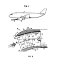
- FIG. 1 an aircraft 2 is shown with a gas turbine engine 4 mounted under the wing.
- the general effect of the wing and engine pylon 5 aerodynamics on the free external airflow is indicated by an arrow 6.
- the free airflow stream is deflected upward in a region just upstream of the engine and nacelle structure to follow an upward slant, blending with the wing airfoil aerodynamics.
- the gas turbine engine 4 is mounted such that the nacelle inlet extends into that portion of the airflow that has been deflected upwards.
- Fig. 2 shows a cross section of the forward portion of a nacelle according to the present invention.
- the nacelle extends upstream of the gas turbine inlet 10 having a nacelle inlet opening 12 which is oriented perpendicularly with respect to the free airstream flow 6.
- the nacelle inlet structure 14 includes an internal surface 16 and an external surface 18.
- the external surface 18 is defined by the loci of the end points of a plurality of radii 20 drawn perpendicular to the external surface centerline 22.
- the external surface centerline 22 is parallel with the flow direction of the free external airflow 6 and forms an angle 24 with respect to the engine centerline 26.
- This angle 24 also termed the droop angle, has been exaggerated for clarity, typically being on the order of 3 to 5 degrees.
- the internal surface 16 of the nacelle structure 14 is defined by the loci of the end points of a plurality of radii 28 drawn perpendicular to a curved centerline 30.
- the curved centerline 30 is colinear wich the external surface centerline 22 at the forward end of the nacelle structure 14 adjacent the nacelle inlet 12, and is colinear with the engine centerline 26 adjacent the engine air inlet 10 at the downstream end of the nacelle structure 14.
- free-flowing external air 6 is separated between an internal flow 32 and an external flow 34.
- the internal flow 32 enters the nacelle inlet 12 and is smoothly turned by the internal surface 16, generally following the curved internal surface centerline 30. The result is that the internal airflow 32 is flowing substantially parallel to the engine centerline 26 by the time it enters the gas turbine air inlet 10.
- the external portion 34 of the divided airflow does not experience this gradual turning, instead continuing to flow substantially linearly about the nacelle exte.nal surface 18 as defined by the linear external surface centerline 22.
- the nacelle 14 By maintaining the generally linear flow of the external air 34, the nacelle 14 according to the present invention reduces the likelihood of the formation of shock waves at the external surface 18 of the nacelle. Such shock waves result in an increased aerodynamic drag and an overall performance penality for the operating aircraft.
- the internal surface 16 aligns and directs the internal airflow 32 with the gas turbine engine centerline 26, reducing losses which occurred in prior art linear duct structures having an abrupt redirection of the internal airflow at the engine inlet plane.
- the overall result is to improve overall performance of the engine and airframe combination without incurring the external aerodynamic drag losses associated with nacelle structures having exterior surfaces developed from curved centerlines as disclosed in the prior art.
Landscapes
- Engineering & Computer Science (AREA)
- Chemical & Material Sciences (AREA)
- Combustion & Propulsion (AREA)
- Mechanical Engineering (AREA)
- General Engineering & Computer Science (AREA)
- Aviation & Aerospace Engineering (AREA)
- Structures Of Non-Positive Displacement Pumps (AREA)
- Wind Motors (AREA)
Applications Claiming Priority (2)
| Application Number | Priority Date | Filing Date | Title |
|---|---|---|---|
| US06/850,644 US4722357A (en) | 1986-04-11 | 1986-04-11 | Gas turbine engine nacelle |
| US850644 | 1986-04-11 |
Publications (3)
| Publication Number | Publication Date |
|---|---|
| EP0241404A2 true EP0241404A2 (de) | 1987-10-14 |
| EP0241404A3 EP0241404A3 (en) | 1988-07-27 |
| EP0241404B1 EP0241404B1 (de) | 1991-06-05 |
Family
ID=25308744
Family Applications (1)
| Application Number | Title | Priority Date | Filing Date |
|---|---|---|---|
| EP19870630054 Expired - Lifetime EP0241404B1 (de) | 1986-04-11 | 1987-04-07 | Triebwerksgondel |
Country Status (6)
| Country | Link |
|---|---|
| US (1) | US4722357A (de) |
| EP (1) | EP0241404B1 (de) |
| JP (1) | JPH0678735B2 (de) |
| CA (1) | CA1257971A (de) |
| DE (1) | DE3770510D1 (de) |
| ES (1) | ES2022438B3 (de) |
Cited By (2)
| Publication number | Priority date | Publication date | Assignee | Title |
|---|---|---|---|---|
| EP2290207A3 (de) * | 2009-05-01 | 2014-10-29 | United Technologies Corporation | Gewölbter Flugzeugmotoreinlass |
| US11421592B2 (en) | 2018-06-15 | 2022-08-23 | Rolls-Royce Plc | Gas turbine engine |
Families Citing this family (120)
| Publication number | Priority date | Publication date | Assignee | Title |
|---|---|---|---|---|
| US4993663A (en) * | 1989-06-01 | 1991-02-19 | General Electric Company | Hybrid laminar flow nacelle |
| US5058617A (en) * | 1990-07-23 | 1991-10-22 | General Electric Company | Nacelle inlet for an aircraft gas turbine engine |
| US5433490A (en) * | 1994-05-09 | 1995-07-18 | General Mills, Inc. | Cooker die removably securing mechanism |
| US5577437A (en) * | 1995-11-06 | 1996-11-26 | General Mills, Inc. | Cooker die removably securing mechanism |
| US5915403A (en) * | 1998-04-14 | 1999-06-29 | The Boeing Company | Biplanar scarfed nacelle inlet |
| US6152021A (en) * | 2000-01-19 | 2000-11-28 | General Mills, Inc. | Cooker die and rotary cutter removably securing mechanism |
| US6167798B1 (en) | 2000-04-19 | 2001-01-02 | General Mills, Inc. | Cooker die and rotary cutter removably securing mechanism |
| US6189439B1 (en) * | 2000-05-25 | 2001-02-20 | General Mills, Inc. | Cooker die and rotary cutter removably securing mechanism |
| US6767198B2 (en) | 2001-10-17 | 2004-07-27 | General Mills, Inc. | Rotary cutter assembly |
| GB0401189D0 (en) * | 2004-01-21 | 2004-02-25 | Rolls Royce Plc | Turbine engine arrangements |
| US8667688B2 (en) | 2006-07-05 | 2014-03-11 | United Technologies Corporation | Method of assembly for gas turbine fan drive gear system |
| US7704178B2 (en) | 2006-07-05 | 2010-04-27 | United Technologies Corporation | Oil baffle for gas turbine fan drive gear system |
| US9976437B2 (en) | 2006-08-15 | 2018-05-22 | United Technologies Corporation | Epicyclic gear train |
| US10107231B2 (en) | 2006-08-15 | 2018-10-23 | United Technologies Corporation | Gas turbine engine with geared architecture |
| US8753243B2 (en) | 2006-08-15 | 2014-06-17 | United Technologies Corporation | Ring gear mounting arrangement with oil scavenge scheme |
| EP2074306A1 (de) | 2006-10-12 | 2009-07-01 | United Technologies Corporation | Integrierte gebläsedüse mit variablem querschnitt und schubumkehrvorrichtung mit doppelfunktionskaskade |
| US7797944B2 (en) | 2006-10-20 | 2010-09-21 | United Technologies Corporation | Gas turbine engine having slim-line nacelle |
| US7870721B2 (en) * | 2006-11-10 | 2011-01-18 | United Technologies Corporation | Gas turbine engine providing simulated boundary layer thickness increase |
| US20080273961A1 (en) | 2007-03-05 | 2008-11-06 | Rosenkrans William E | Flutter sensing and control system for a gas turbine engine |
| US8408491B2 (en) * | 2007-04-24 | 2013-04-02 | United Technologies Corporation | Nacelle assembly having inlet airfoil for a gas turbine engine |
| US8205430B2 (en) * | 2007-05-16 | 2012-06-26 | United Technologies Corporation | Variable geometry nacelle assembly for a gas turbine engine |
| US8727267B2 (en) * | 2007-05-18 | 2014-05-20 | United Technologies Corporation | Variable contraction ratio nacelle assembly for a gas turbine engine |
| US20080310956A1 (en) * | 2007-06-13 | 2008-12-18 | Jain Ashok K | Variable geometry gas turbine engine nacelle assembly with nanoelectromechanical system |
| US20080308684A1 (en) * | 2007-06-15 | 2008-12-18 | Chaudhry Zaffir A | Nacelle with articulating leading edge slates |
| US8402739B2 (en) * | 2007-06-28 | 2013-03-26 | United Technologies Corporation | Variable shape inlet section for a nacelle assembly of a gas turbine engine |
| US9228534B2 (en) * | 2007-07-02 | 2016-01-05 | United Technologies Corporation | Variable contour nacelle assembly for a gas turbine engine |
| US11346289B2 (en) | 2007-08-01 | 2022-05-31 | Raytheon Technologies Corporation | Turbine section of high bypass turbofan |
| US11486311B2 (en) | 2007-08-01 | 2022-11-01 | Raytheon Technologies Corporation | Turbine section of high bypass turbofan |
| US11149650B2 (en) | 2007-08-01 | 2021-10-19 | Raytheon Technologies Corporation | Turbine section of high bypass turbofan |
| US8844265B2 (en) | 2007-08-01 | 2014-09-30 | United Technologies Corporation | Turbine section of high bypass turbofan |
| US20150377123A1 (en) | 2007-08-01 | 2015-12-31 | United Technologies Corporation | Turbine section of high bypass turbofan |
| US9701415B2 (en) | 2007-08-23 | 2017-07-11 | United Technologies Corporation | Gas turbine engine with axial movable fan variable area nozzle |
| US9957918B2 (en) | 2007-08-28 | 2018-05-01 | United Technologies Corporation | Gas turbine engine front architecture |
| US20140157754A1 (en) | 2007-09-21 | 2014-06-12 | United Technologies Corporation | Gas turbine engine compressor arrangement |
| US9004399B2 (en) * | 2007-11-13 | 2015-04-14 | United Technologies Corporation | Nacelle flow assembly |
| US8192147B2 (en) * | 2007-12-14 | 2012-06-05 | United Technologies Corporation | Nacelle assembly having inlet bleed |
| US8186942B2 (en) * | 2007-12-14 | 2012-05-29 | United Technologies Corporation | Nacelle assembly with turbulators |
| US8529188B2 (en) * | 2007-12-17 | 2013-09-10 | United Technologies Corporation | Fan nacelle flow control |
| US20140174056A1 (en) | 2008-06-02 | 2014-06-26 | United Technologies Corporation | Gas turbine engine with low stage count low pressure turbine |
| US9885313B2 (en) | 2009-03-17 | 2018-02-06 | United Technologes Corporation | Gas turbine engine bifurcation located fan variable area nozzle |
| US9995174B2 (en) | 2010-10-12 | 2018-06-12 | United Technologies Corporation | Planetary gear system arrangement with auxiliary oil system |
| US10605167B2 (en) | 2011-04-15 | 2020-03-31 | United Technologies Corporation | Gas turbine engine front center body architecture |
| US9631558B2 (en) | 2012-01-03 | 2017-04-25 | United Technologies Corporation | Geared architecture for high speed and small volume fan drive turbine |
| US9410608B2 (en) | 2011-06-08 | 2016-08-09 | United Technologies Corporation | Flexible support structure for a geared architecture gas turbine engine |
| US9239012B2 (en) | 2011-06-08 | 2016-01-19 | United Technologies Corporation | Flexible support structure for a geared architecture gas turbine engine |
| US12331691B2 (en) | 2011-12-27 | 2025-06-17 | Rtx Corporation | Gas turbine engine compressor arrangement |
| US9416677B2 (en) | 2012-01-10 | 2016-08-16 | United Technologies Corporation | Gas turbine engine forward bearing compartment architecture |
| US20130186058A1 (en) | 2012-01-24 | 2013-07-25 | William G. Sheridan | Geared turbomachine fan and compressor rotation |
| US8869508B2 (en) | 2012-01-31 | 2014-10-28 | United Technologies Corporation | Gas turbine engine variable area fan nozzle control |
| US20130192251A1 (en) | 2012-01-31 | 2013-08-01 | Peter M. Munsell | Buffer system that communicates buffer supply air to one or more portions of a gas turbine engine |
| US9169781B2 (en) | 2012-01-31 | 2015-10-27 | United Technologies Corporation | Turbine engine gearbox |
| US10400629B2 (en) | 2012-01-31 | 2019-09-03 | United Technologies Corporation | Gas turbine engine shaft bearing configuration |
| US20130192191A1 (en) | 2012-01-31 | 2013-08-01 | Frederick M. Schwarz | Gas turbine engine with high speed low pressure turbine section and bearing support features |
| US20130192198A1 (en) | 2012-01-31 | 2013-08-01 | Lisa I. Brilliant | Compressor flowpath |
| US20160130949A1 (en) | 2012-01-31 | 2016-05-12 | United Technologies Corporation | Low noise turbine for geared turbofan engine |
| US10415468B2 (en) | 2012-01-31 | 2019-09-17 | United Technologies Corporation | Gas turbine engine buffer system |
| US10724431B2 (en) | 2012-01-31 | 2020-07-28 | Raytheon Technologies Corporation | Buffer system that communicates buffer supply air to one or more portions of a gas turbine engine |
| US10287914B2 (en) | 2012-01-31 | 2019-05-14 | United Technologies Corporation | Gas turbine engine with high speed low pressure turbine section and bearing support features |
| US10107191B2 (en) | 2012-02-29 | 2018-10-23 | United Technologies Corporation | Geared gas turbine engine with reduced fan noise |
| US10125693B2 (en) | 2012-04-02 | 2018-11-13 | United Technologies Corporation | Geared turbofan engine with power density range |
| US10138809B2 (en) | 2012-04-02 | 2018-11-27 | United Technologies Corporation | Geared turbofan engine with a high ratio of thrust to turbine volume |
| US8572943B1 (en) | 2012-05-31 | 2013-11-05 | United Technologies Corporation | Fundamental gear system architecture |
| WO2014099087A2 (en) | 2012-09-28 | 2014-06-26 | United Technologies Corporation | Method of assembly for gas turbine fan drive gear system |
| WO2014058453A1 (en) | 2012-10-08 | 2014-04-17 | United Technologies Corporation | Geared turbine engine with relatively lightweight propulsor module |
| US11280271B2 (en) | 2012-10-09 | 2022-03-22 | Raytheon Technologies Corporation | Operability geared turbofan engine including compressor section variable guide vanes |
| US9932933B2 (en) | 2012-12-20 | 2018-04-03 | United Technologies Corporation | Low pressure ratio fan engine having a dimensional relationship between inlet and fan size |
| US9920653B2 (en) | 2012-12-20 | 2018-03-20 | United Technologies Corporation | Low pressure ratio fan engine having a dimensional relationship between inlet and fan size |
| US11480104B2 (en) | 2013-03-04 | 2022-10-25 | Raytheon Technologies Corporation | Gas turbine engine inlet |
| US9863326B2 (en) | 2013-03-12 | 2018-01-09 | United Technologies Corporation | Flexible coupling for geared turbine engine |
| US10605172B2 (en) | 2013-03-14 | 2020-03-31 | United Technologies Corporation | Low noise turbine for geared gas turbine engine |
| US11719161B2 (en) | 2013-03-14 | 2023-08-08 | Raytheon Technologies Corporation | Low noise turbine for geared gas turbine engine |
| WO2014151785A1 (en) | 2013-03-15 | 2014-09-25 | United Technologies Corporation | Turbofan engine bearing and gearbox arrangement |
| US10724479B2 (en) | 2013-03-15 | 2020-07-28 | United Technologies Corporation | Thrust efficient turbofan engine |
| US10287917B2 (en) | 2013-05-09 | 2019-05-14 | United Technologies Corporation | Turbofan engine front section |
| EP3957847A1 (de) | 2013-05-09 | 2022-02-23 | Raytheon Technologies Corporation | Stirnteil für turbofantriebwerk |
| WO2015088619A2 (en) | 2013-10-16 | 2015-06-18 | United Technologies Corporation | Geared turbofan engine with targeted modular efficiency |
| US10502163B2 (en) | 2013-11-01 | 2019-12-10 | United Technologies Corporation | Geared turbofan arrangement with core split power ratio |
| WO2015112212A2 (en) | 2013-11-01 | 2015-07-30 | United Technologies Corporation | Geared turbofan arrangement with core split power ratio |
| US8869504B1 (en) | 2013-11-22 | 2014-10-28 | United Technologies Corporation | Geared turbofan engine gearbox arrangement |
| US10584715B2 (en) | 2014-02-19 | 2020-03-10 | United Technologies Corporation | Gas turbine engine airfoil |
| EP3108120B1 (de) | 2014-02-19 | 2021-03-31 | Raytheon Technologies Corporation | Gasturbinentriebwerk mit einer getriebearchitektur und einer spezifischen festen schaufelstruktur |
| WO2015175052A2 (en) | 2014-02-19 | 2015-11-19 | United Technologies Corporation | Gas turbine engine airfoil |
| US10495106B2 (en) | 2014-02-19 | 2019-12-03 | United Technologies Corporation | Gas turbine engine airfoil |
| US10570915B2 (en) | 2014-02-19 | 2020-02-25 | United Technologies Corporation | Gas turbine engine airfoil |
| WO2015175043A2 (en) | 2014-02-19 | 2015-11-19 | United Technologies Corporation | Gas turbine engine airfoil |
| US10570916B2 (en) | 2014-02-19 | 2020-02-25 | United Technologies Corporation | Gas turbine engine airfoil |
| US10465702B2 (en) | 2014-02-19 | 2019-11-05 | United Technologies Corporation | Gas turbine engine airfoil |
| US10280843B2 (en) | 2014-03-07 | 2019-05-07 | United Technologies Corporation | Geared turbofan with integral front support and carrier |
| US9976490B2 (en) | 2014-07-01 | 2018-05-22 | United Technologies Corporation | Geared gas turbine engine with oil deaerator |
| US10060289B2 (en) | 2014-07-29 | 2018-08-28 | United Technologies Corporation | Geared gas turbine engine with oil deaerator and air removal |
| GB201418322D0 (en) * | 2014-10-16 | 2014-12-03 | Rolls Royce Plc | Gas turbine engine nacelle |
| US9915225B2 (en) | 2015-02-06 | 2018-03-13 | United Technologies Corporation | Propulsion system arrangement for turbofan gas turbine engine |
| US9470093B2 (en) | 2015-03-18 | 2016-10-18 | United Technologies Corporation | Turbofan arrangement with blade channel variations |
| US10371168B2 (en) | 2015-04-07 | 2019-08-06 | United Technologies Corporation | Modal noise reduction for gas turbine engine |
| US10458270B2 (en) | 2015-06-23 | 2019-10-29 | United Technologies Corporation | Roller bearings for high ratio geared turbofan engine |
| US9815560B2 (en) * | 2015-09-21 | 2017-11-14 | General Electric Company | AFT engine nacelle shape for an aircraft |
| US9957055B2 (en) | 2015-09-21 | 2018-05-01 | General Electric Company | Aft engine for an aircraft |
| US9821917B2 (en) | 2015-09-21 | 2017-11-21 | General Electric Company | Aft engine for an aircraft |
| US9884687B2 (en) | 2015-09-21 | 2018-02-06 | General Electric Company | Non-axis symmetric aft engine |
| US9637217B2 (en) | 2015-09-21 | 2017-05-02 | General Electric Company | Aircraft having an aft engine |
| US10017270B2 (en) | 2015-10-09 | 2018-07-10 | General Electric Company | Aft engine for an aircraft |
| US10508562B2 (en) | 2015-12-01 | 2019-12-17 | United Technologies Corporation | Geared turbofan with four star/planetary gear reduction |
| US10669948B2 (en) | 2017-01-03 | 2020-06-02 | Raytheon Technologies Corporation | Geared turbofan with non-epicyclic gear reduction system |
| US10738646B2 (en) | 2017-06-12 | 2020-08-11 | Raytheon Technologies Corporation | Geared turbine engine with gear driving low pressure compressor and fan at common speed, and failsafe overspeed protection and shear section |
| US10724445B2 (en) | 2018-01-03 | 2020-07-28 | Raytheon Technologies Corporation | Method of assembly for fan drive gear system with rotating carrier |
| US11097849B2 (en) | 2018-09-10 | 2021-08-24 | General Electric Company | Aircraft having an aft engine |
| GB2577075B (en) * | 2018-09-12 | 2022-11-02 | Reaction Engines Ltd | Engine module |
| US11092020B2 (en) | 2018-10-18 | 2021-08-17 | Raytheon Technologies Corporation | Rotor assembly for gas turbine engines |
| GB201917415D0 (en) * | 2019-11-29 | 2020-01-15 | Rolls Royce Plc | Nacelle for a gas turbine engine |
| GB202001971D0 (en) * | 2020-02-13 | 2020-04-01 | Rolls Royce Plc | Nacelle for gas turbine engine and aircraft comprising the same |
| US11781506B2 (en) | 2020-06-03 | 2023-10-10 | Rtx Corporation | Splitter and guide vane arrangement for gas turbine engines |
| US11754000B2 (en) | 2021-07-19 | 2023-09-12 | Rtx Corporation | High and low spool configuration for a gas turbine engine |
| US12392280B2 (en) | 2021-07-19 | 2025-08-19 | Rtx Corporation | Gas turbine engine with high low spool power extraction ratio |
| US11814968B2 (en) | 2021-07-19 | 2023-11-14 | Rtx Corporation | Gas turbine engine with idle thrust ratio |
| US11719245B2 (en) | 2021-07-19 | 2023-08-08 | Raytheon Technologies Corporation | Compressor arrangement for a gas turbine engine |
| US12123356B2 (en) | 2021-07-19 | 2024-10-22 | Rtx Corporation | Gas turbine engine with higher low spool torque-to-thrust ratio |
| US20250059933A1 (en) * | 2023-08-14 | 2025-02-20 | The Boeing Company | Method of Nacelle Air Heat Exchanger Integration for a Hydrogen Fueled Fuel Cell Powered Aircraft |
| US12442333B1 (en) | 2024-10-09 | 2025-10-14 | General Electric Company | Turbine engine having a variable engine intake system |
| US12435666B1 (en) | 2024-10-09 | 2025-10-07 | General Electric Company | Turbine engine having a variable engine intake system |
| US12529335B1 (en) | 2024-10-09 | 2026-01-20 | General Electric Company | Turbine engine having a variable engine intake system |
Family Cites Families (5)
| Publication number | Priority date | Publication date | Assignee | Title |
|---|---|---|---|---|
| DE1906157A1 (de) * | 1969-02-07 | 1970-08-13 | Messerschmitt Boelkow Blohm | Zusatzlufteinlassanordnung fuer die Triebwerke von Luft- und Raumfahrzeugen |
| US3765623A (en) * | 1971-10-04 | 1973-10-16 | Mc Donnell Douglas Corp | Air inlet |
| US4449683A (en) * | 1979-01-03 | 1984-05-22 | The Boeing Company | Aerodynamically contoured, low drag wing engine and engine nacelle combination |
| US4220171A (en) * | 1979-05-14 | 1980-09-02 | The United States Of America As Represented By The Administrator Of The National Aeronautics And Space Administration | Curved centerline air intake for a gas turbine engine |
| GB2064005A (en) * | 1979-11-22 | 1981-06-10 | Rolls Royce | Air Intake to Ducted Fan Engine |
-
1986
- 1986-04-11 US US06/850,644 patent/US4722357A/en not_active Expired - Lifetime
-
1987
- 1987-03-23 CA CA000532736A patent/CA1257971A/en not_active Expired
- 1987-04-03 JP JP8368787A patent/JPH0678735B2/ja not_active Expired - Lifetime
- 1987-04-07 DE DE8787630054T patent/DE3770510D1/de not_active Expired - Lifetime
- 1987-04-07 EP EP19870630054 patent/EP0241404B1/de not_active Expired - Lifetime
- 1987-04-07 ES ES87630054T patent/ES2022438B3/es not_active Expired - Lifetime
Cited By (2)
| Publication number | Priority date | Publication date | Assignee | Title |
|---|---|---|---|---|
| EP2290207A3 (de) * | 2009-05-01 | 2014-10-29 | United Technologies Corporation | Gewölbter Flugzeugmotoreinlass |
| US11421592B2 (en) | 2018-06-15 | 2022-08-23 | Rolls-Royce Plc | Gas turbine engine |
Also Published As
| Publication number | Publication date |
|---|---|
| JPH0678735B2 (ja) | 1994-10-05 |
| DE3770510D1 (de) | 1991-07-11 |
| US4722357A (en) | 1988-02-02 |
| EP0241404A3 (en) | 1988-07-27 |
| ES2022438B3 (es) | 1991-12-01 |
| EP0241404B1 (de) | 1991-06-05 |
| CA1257971A (en) | 1989-08-01 |
| JPS62243931A (ja) | 1987-10-24 |
Similar Documents
| Publication | Publication Date | Title |
|---|---|---|
| US4722357A (en) | Gas turbine engine nacelle | |
| US4466587A (en) | Nacelle installation | |
| US4836473A (en) | Apparatus for influencing a boundary layer on the surface of a body moving through a medium | |
| EP1243782B1 (de) | Doppelter Einlass eines Strahltriebwerks | |
| US5058617A (en) | Nacelle inlet for an aircraft gas turbine engine | |
| US2694357A (en) | Boundary layer energization for flush inlets | |
| US7967241B2 (en) | Supersonic aircraft jet engine installation | |
| US4993663A (en) | Hybrid laminar flow nacelle | |
| EP3109153B1 (de) | Pfeilgradientgrenzschichtumlenker | |
| US5443230A (en) | Aircraft wing/nacelle combination | |
| CA1263242A (en) | Gas turbine outlet arrangement | |
| US4629147A (en) | Over-the-wing propeller | |
| GB2259115A (en) | Aircraft engine nacelle profile | |
| US9126679B2 (en) | Airplane including means for taking at least a portion of the boundary layer of the flow of air over a surface | |
| US3583661A (en) | Air intake for turbojet aircraft engine | |
| EP0103478A1 (de) | Aerodynamisches Profil | |
| EP0052360B1 (de) | Luftansaugvorrichtung einer Flugzeug-Gasturbine | |
| GB2259114A (en) | Aircraft engine nacelle profile | |
| RU2092382C1 (ru) | Носовая часть фюзеляжа высокоскоростного летательного аппарата с воздушно-реактивным двигателем | |
| RU2838700C1 (ru) | Магистральный самолет с гибридной силовой установкой | |
| JPH07179199A (ja) | 円弧輪郭を有する航空機エンジンナセル | |
| RU2007331C1 (ru) | Носовая часть высокоскоростного летательного аппарата с воздушно-реактивным двигателем | |
| CN117836207A (zh) | 用于航空器的升力、推进和控制的系统 |
Legal Events
| Date | Code | Title | Description |
|---|---|---|---|
| PUAI | Public reference made under article 153(3) epc to a published international application that has entered the european phase |
Free format text: ORIGINAL CODE: 0009012 |
|
| AK | Designated contracting states |
Kind code of ref document: A2 Designated state(s): BE DE ES FR GB IT NL |
|
| PUAL | Search report despatched |
Free format text: ORIGINAL CODE: 0009013 |
|
| AK | Designated contracting states |
Kind code of ref document: A3 Designated state(s): BE DE ES FR GB IT NL |
|
| 17P | Request for examination filed |
Effective date: 19890106 |
|
| 17Q | First examination report despatched |
Effective date: 19900226 |
|
| GRAA | (expected) grant |
Free format text: ORIGINAL CODE: 0009210 |
|
| AK | Designated contracting states |
Kind code of ref document: B1 Designated state(s): BE DE ES FR GB IT NL |
|
| ET | Fr: translation filed | ||
| REF | Corresponds to: |
Ref document number: 3770510 Country of ref document: DE Date of ref document: 19910711 |
|
| ITF | It: translation for a ep patent filed | ||
| PLBE | No opposition filed within time limit |
Free format text: ORIGINAL CODE: 0009261 |
|
| STAA | Information on the status of an ep patent application or granted ep patent |
Free format text: STATUS: NO OPPOSITION FILED WITHIN TIME LIMIT |
|
| 26N | No opposition filed | ||
| PGFP | Annual fee paid to national office [announced via postgrant information from national office to epo] |
Ref country code: ES Payment date: 19930326 Year of fee payment: 7 |
|
| PGFP | Annual fee paid to national office [announced via postgrant information from national office to epo] |
Ref country code: BE Payment date: 19930329 Year of fee payment: 7 |
|
| PGFP | Annual fee paid to national office [announced via postgrant information from national office to epo] |
Ref country code: NL Payment date: 19930430 Year of fee payment: 7 |
|
| PG25 | Lapsed in a contracting state [announced via postgrant information from national office to epo] |
Ref country code: ES Free format text: LAPSE BECAUSE OF NON-PAYMENT OF DUE FEES Effective date: 19940408 |
|
| PG25 | Lapsed in a contracting state [announced via postgrant information from national office to epo] |
Ref country code: BE Effective date: 19940430 |
|
| BERE | Be: lapsed |
Owner name: UNITED TECHNOLOGIES CORP. Effective date: 19940430 |
|
| PG25 | Lapsed in a contracting state [announced via postgrant information from national office to epo] |
Ref country code: NL Effective date: 19941101 |
|
| NLV4 | Nl: lapsed or anulled due to non-payment of the annual fee | ||
| REG | Reference to a national code |
Ref country code: ES Ref legal event code: FD2A Effective date: 19990201 |
|
| PGFP | Annual fee paid to national office [announced via postgrant information from national office to epo] |
Ref country code: FR Payment date: 19990315 Year of fee payment: 13 |
|
| PGFP | Annual fee paid to national office [announced via postgrant information from national office to epo] |
Ref country code: GB Payment date: 19990323 Year of fee payment: 13 |
|
| PGFP | Annual fee paid to national office [announced via postgrant information from national office to epo] |
Ref country code: DE Payment date: 19990326 Year of fee payment: 13 |
|
| PG25 | Lapsed in a contracting state [announced via postgrant information from national office to epo] |
Ref country code: GB Free format text: LAPSE BECAUSE OF NON-PAYMENT OF DUE FEES Effective date: 20000407 |
|
| GBPC | Gb: european patent ceased through non-payment of renewal fee |
Effective date: 20000407 |
|
| PG25 | Lapsed in a contracting state [announced via postgrant information from national office to epo] |
Ref country code: FR Free format text: LAPSE BECAUSE OF NON-PAYMENT OF DUE FEES Effective date: 20001229 |
|
| PG25 | Lapsed in a contracting state [announced via postgrant information from national office to epo] |
Ref country code: DE Free format text: LAPSE BECAUSE OF NON-PAYMENT OF DUE FEES Effective date: 20010201 |
|
| REG | Reference to a national code |
Ref country code: FR Ref legal event code: ST |
|
| PG25 | Lapsed in a contracting state [announced via postgrant information from national office to epo] |
Ref country code: IT Free format text: LAPSE BECAUSE OF NON-PAYMENT OF DUE FEES;WARNING: LAPSES OF ITALIAN PATENTS WITH EFFECTIVE DATE BEFORE 2007 MAY HAVE OCCURRED AT ANY TIME BEFORE 2007. THE CORRECT EFFECTIVE DATE MAY BE DIFFERENT FROM THE ONE RECORDED. Effective date: 20050407 |