EP0241422A1 - Scie à chaîne mobile pour travailler du béton, de la pierre et de la maçonnerie - Google Patents
Scie à chaîne mobile pour travailler du béton, de la pierre et de la maçonnerie Download PDFInfo
- Publication number
- EP0241422A1 EP0241422A1 EP19870810195 EP87810195A EP0241422A1 EP 0241422 A1 EP0241422 A1 EP 0241422A1 EP 19870810195 EP19870810195 EP 19870810195 EP 87810195 A EP87810195 A EP 87810195A EP 0241422 A1 EP0241422 A1 EP 0241422A1
- Authority
- EP
- European Patent Office
- Prior art keywords
- guide
- shaft
- mobile
- hollow shaft
- coupling
- Prior art date
- Legal status (The legal status is an assumption and is not a legal conclusion. Google has not performed a legal analysis and makes no representation as to the accuracy of the status listed.)
- Granted
Links
Images
Classifications
-
- B—PERFORMING OPERATIONS; TRANSPORTING
- B28—WORKING CEMENT, CLAY, OR STONE
- B28D—WORKING STONE OR STONE-LIKE MATERIALS
- B28D1/00—Working stone or stone-like materials, e.g. brick, concrete or glass, not provided for elsewhere; Machines, devices, tools therefor
- B28D1/02—Working stone or stone-like materials, e.g. brick, concrete or glass, not provided for elsewhere; Machines, devices, tools therefor by sawing
- B28D1/08—Working stone or stone-like materials, e.g. brick, concrete or glass, not provided for elsewhere; Machines, devices, tools therefor by sawing with saw-blades of endless cutter-type, e.g. chain saws, i.e. saw chains, strap saws
- B28D1/082—Working stone or stone-like materials, e.g. brick, concrete or glass, not provided for elsewhere; Machines, devices, tools therefor by sawing with saw-blades of endless cutter-type, e.g. chain saws, i.e. saw chains, strap saws consisting of chain saws
- B28D1/084—Working stone or stone-like materials, e.g. brick, concrete or glass, not provided for elsewhere; Machines, devices, tools therefor by sawing with saw-blades of endless cutter-type, e.g. chain saws, i.e. saw chains, strap saws consisting of chain saws the saw chains being mounted on a pivotingly adjustable arm
Definitions
- the invention relates to a mobile chain saw for the processing of concrete, stone and masonry with a drive unit, a feed unit, a swivel with a saw chain and a guide device.
- chain saws which have saw chains which are particularly suitable for stone work.
- a chainsaw is known for example from German Patent No. 2 207 065.
- This known chain saw has a drive unit with a heavy electric motor, the drive shaft of which Feed unit is guided and connected to the chain drive.
- the saw chain is guided over the chain drive and the sword and equipped with diamond disks.
- the drive unit with the sword and the feed unit are held by a support device which is screwed onto the masonry.
- This support device consists of a fixed frame with lateral guideways for rollers.
- Drive and feed unit are fastened in a housing which is provided with several rollers on the underside.
- rollers engage in the guideways of the support device, one row being arranged vertically and the other row being arranged horizontally.
- An additional feed device is arranged next to the drive unit.
- the drive unit with the saw chain running around the sword can be moved along the support device forming a guide device.
- punctures and joints in walls and the like can be easily made.
- the setup is very difficult and the assembly is complex. Replacing the sword or the drive unit is time-consuming and leads to long downtimes.
- the chain saw should have a low weight, and swords and circular saw blades of different lengths can be used and easily exchanged on the same feed and drive unit.
- the device according to the invention has considerable advantages over the known mobile sawing devices.
- the Feed unit with the continuous drive shaft forms a stable connection to the guide device with its housing.
- the drive device and the coupling device are connected to the drive shaft in the feed unit by pluggable couplings. If the drive unit is defective, it can be easily replaced without having to remove any parts on the feed unit or on the side of the chainsaw. Since the coupling device can be separated from the feed unit in a simple manner, swords with different dimensions or with differently equipped saw chains can be exchanged easily and quickly, the entire detachable coupling unit being advantageously replaced together with the sword and the saw chain.
- the assembly of the entire sawing device for example on a wall, is considerably simplified since at least the coupling part with the sword and, if necessary, the drive unit, are removed for the provision of the device. If the guide device and the feed unit are arranged in the desired cutting position, the cutting tool with the coupling device can be quickly and easily connected to the feed unit again. Due to the coupling unit, which is firmly connected to the hollow shaft on the one hand and to which the sword is attached on the other hand, the sword can be pivoted about the axis of the drive shaft via the hollow shaft.
- This arrangement according to the invention has the advantages that cuts can be made to side surfaces, but also that plunging into full surfaces is possible.
- a coupling device with a circular saw blade attached to it can be attached to the feed unit instead of the chainsaw. Since smaller circular saw blades are relatively cheap, there is another cost advantage.
- a boom with an intermediate gear is arranged on the intermediate piece, at the end of which the circular saw blade is attached. This arrangement enables piercing into full areas with circular saw blades.
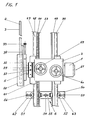
- the mobile chain saw according to FIG. 1 consists of a feed unit 2, a drive unit 1, a coupling device 5, a sword 3 with a saw chain 4 and a guide device 6.
- the drive unit 1 is a hydraulic motor which is connected to a hydraulic unit (not shown) via connecting lines.
- the feed unit 2 contains two independent gears, not shown, one of which enables the chain saw to be fed along the two guide rails 48, 49 via the handwheel 59 and the toothed rack 44.
- the sword 3 can be pivoted about the axis 61 via the handwheel 60.
- the sword 3 is surrounded in the region of the axis 61 by a protective housing 58 and connected to the clamping plate 22 via a connecting plate 34.
- Clamping plate 22 and sword 3 are displaceable with respect to the axis 61, whereby the saw chain 4 can be tensioned.
- a clamping screw 33 is arranged on the clamping plate 22.
- the position of the anchoring elements 54 is initially determined depending on the desired position and direction of the cut.
- the anchoring elements 54 are used to fasten cross members 50.
- the anchoring element 54 is a screw which engages in a drilling plug in the concrete wall.
- the cross member 50 is further equipped with two clamping devices 51, 52 for clamping the guide rails 48, 49. Clamping claws on the clamping devices 51, 52 encompass the base plate 53, which is firmly connected to the rails 48, 49 and clamp them against the cross member 50.
- the tensioning devices 51, 52 are displaceable in the slots 62, 63 in the cross member 50 and enable the guide rails 48, 49 to be precisely aligned.
- the anchoring element 54 is also arranged in an elongated hole 55, which results in a further setting possibility.
- Leveling screws 56, 57 are arranged on both sides of the cross member 50. The guide device can be easily disassembled into its individual parts and transported in a simple manner.
- rails 43 are fastened to the guide rails 48, 49 and cooperate with C-shaped guide elements 40.
- the guide elements 40 are rollers which are connected to the housing foot 41 of the feed unit 2 via a bearing pin and the screw 42.
- the feed unit 2 is equipped with four such guide elements 40, two of which embrace the rail 43 and the other two the rail 39, which is fastened to the guide rail 49 and is also directed outwards.
- the feed unit 2 is guided without play in all directions.
- the feed is generated by the handwheel 59 shown in FIG. 1 via the gear 46, the feed pinion 45 and the rack 44.
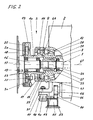
- a drive shaft 7 is arranged in the feed unit 2.
- This drive shaft 7 has the longitudinal axis 61 and extends through the feed unit 2.
- the drive shaft 7 is mounted in a hollow shaft 8 via the bearings 27 and has a multi-spline pin 26 at the end shown.
- Via a multi-spline sleeve 24, the drive shaft 7 is positively connected to a multi-spline pin 25 on the coupling shaft 16.
- At the other end of the drive shaft 7 there is a similar connection to the output shaft of the drive unit 1.
- the coupling shaft 16 has a tool flange 17 and is mounted in the intermediate piece 10 via the bearings 23. On the tool flange 17 is by means of Several screws 19 fastened the drive wheel 18 for the saw chain 3.
- the hollow shaft 8 is supported by bearings 28 in the housing of the feed unit 2. In the interior of the feed unit 2, it is connected to a gear which interacts with the handwheel 60 shown in FIG. 1 and enables the hollow shaft 8 to be rotated about the axis 61.
- a guide flange 9 is arranged, which has a conical bore 64. This conical bore 64 serves to center the intermediate piece 10, which is provided at one end with a guide cone 12.
- the intermediate piece 10 further has connecting flanges 11 and a fastening flange 13.
- the connecting flanges 11 are distributed symmetrically on the circumference of the intermediate piece 10, and recesses 14 are arranged between the flanges 11.
- the connecting flanges 11 are surrounded by a clamping ring 29 with a collar 30. Openings are also arranged in the collar 30 of the clamping ring 29, which are slightly larger than the connecting flanges 11 on the intermediate piece 10. Thanks to this configuration, the intermediate piece 10 can be moved out of the clamping ring 29.
- the threaded part 31 on the clamping ring 29 and on the guide flange 9 is used for the fixed connection of the intermediate piece 10 with the hollow shaft 8.
- the threaded part 31 on the clamping ring 29 and on the guide flange 9 is used for the fixed connection of the intermediate piece 10 with the hollow shaft 8.
- the connecting flanges 11 are pulled against the hollow shaft 8 and the intermediate piece 10 is firmly connected to the hollow shaft 8.
- 8 transmission elements 15 in the form of radially arranged wedges are attached to the guide flange 9 of the hollow shaft. These wedges engage in corresponding recesses on the connecting flange 11.
- the sword 3 is adjusted for tensioning the saw chain 4 by moving the tensioning plate 22 along the guide plate 20.
- the tensioning plate 22 engages around the guide plate 20 in a C-shape and is provided with corresponding fixing means, not shown.
- the guide plate 20 is in turn firmly connected by means of screws 21 to the mounting flange 13 or the intermediate piece 10.
- the blade 3 including the saw chain 4, the drive wheel 18, the coupling shaft 16, the guide and clamping plates 20, 22 and the intermediate piece 10 are replaced by loosening the clamping ring 29 and pulling out the entire coupling part 5.
- To loosen and clamp the clamping ring 29 this is equipped on the circumference with holes 32 into which a clamping tool can be inserted.
- the clamping ring 29 and the power transmission elements 15 remain on the hollow shaft 8.
- a differently dimensioned sword 3, which is already firmly connected to a coupling device 5, can be quickly and easily connected to the feed unit 2 and brought into connection with the drive shaft 7 and by tensioning the Clamping ring 29 are firmly connected to the hollow shaft 8.
- the saw chain 4 is driven directly by the drive unit 1 via the drive shaft 7 and the coupling shaft 16.
- the hollow shaft 8, the intermediate piece 10 and the guide and clamping plates 20, 22 are stationary and can only be pivoted via the handwheel 60.
Landscapes
- Engineering & Computer Science (AREA)
- Mining & Mineral Resources (AREA)
- Mechanical Engineering (AREA)
- Processing Of Stones Or Stones Resemblance Materials (AREA)
- Underground Or Underwater Handling Of Building Materials (AREA)
Priority Applications (1)
| Application Number | Priority Date | Filing Date | Title |
|---|---|---|---|
| AT87810195T ATE64712T1 (de) | 1986-04-05 | 1987-04-01 | Mobile kettensaege fuer die bearbeitung von beton, gesteinen und mauerwerk. |
Applications Claiming Priority (2)
| Application Number | Priority Date | Filing Date | Title |
|---|---|---|---|
| CH1329/86A CH670215A5 (fr) | 1986-04-05 | 1986-04-05 | |
| CH1329/86 | 1986-04-05 |
Publications (2)
| Publication Number | Publication Date |
|---|---|
| EP0241422A1 true EP0241422A1 (fr) | 1987-10-14 |
| EP0241422B1 EP0241422B1 (fr) | 1991-06-26 |
Family
ID=4207923
Family Applications (1)
| Application Number | Title | Priority Date | Filing Date |
|---|---|---|---|
| EP87810195A Expired - Lifetime EP0241422B1 (fr) | 1986-04-05 | 1987-04-01 | Scie à chaîne mobile pour travailler du béton, de la pierre et de la maçonnerie |
Country Status (4)
| Country | Link |
|---|---|
| EP (1) | EP0241422B1 (fr) |
| AT (1) | ATE64712T1 (fr) |
| CH (1) | CH670215A5 (fr) |
| DE (1) | DE3770974D1 (fr) |
Cited By (4)
| Publication number | Priority date | Publication date | Assignee | Title |
|---|---|---|---|---|
| EP0656248A1 (fr) * | 1993-12-03 | 1995-06-07 | CAR. MEC. S.r.l. | Innovations de machines à scier pour blocs de carrière |
| WO2008059313A1 (fr) * | 2006-11-13 | 2008-05-22 | Md Modelleria Dario F.Lli S.N.C. | Machine à scier, de type scie à ruban ou similaire, pour pierre, marbre, bois ou autres sortes de matériaux, avec plan de coupe réglable sur différentes positions |
| DE102008002454A1 (de) | 2007-06-27 | 2009-01-08 | Metso Paper, Inc. | Papiermaschinenwalze und Schwingungstilger |
| CN106442062A (zh) * | 2016-11-01 | 2017-02-22 | 贵州大学 | 一种实验煤岩样快速精准加工装置及方法 |
Families Citing this family (1)
| Publication number | Priority date | Publication date | Assignee | Title |
|---|---|---|---|---|
| SE543428C2 (en) | 2019-06-24 | 2021-02-16 | Husqvarna Ab | A rotatable cutting chain work tool, a wall saw arrangement comprising such a work tool, an annular member and a method for producing an annular member |
Citations (5)
| Publication number | Priority date | Publication date | Assignee | Title |
|---|---|---|---|---|
| US1676428A (en) * | 1925-05-29 | 1928-07-10 | Goodman Mfg Co | Mining machine |
| CH387922A (fr) * | 1961-11-24 | 1965-02-15 | Bergborrmaskiner Ab | Scie mécanique |
| DE2207065B1 (de) * | 1972-02-15 | 1973-09-06 | Maschinenfabrik Korfmann Gmbh, 5810 Witten | Maschine zum schneiden von gesteinsmaterial |
| DE2228691B1 (de) * | 1972-06-13 | 1973-09-27 | Maschinenfabrik Korfmann Gmbh, 5810 Witten | Spannvorrichtung für hochtourige Steinschneidketten |
| DE2300737A1 (de) * | 1971-04-08 | 1974-07-18 | Continental Drilling Co | Saegenanordnung |
-
1986
- 1986-04-05 CH CH1329/86A patent/CH670215A5/de not_active IP Right Cessation
-
1987
- 1987-04-01 DE DE8787810195T patent/DE3770974D1/de not_active Expired - Fee Related
- 1987-04-01 AT AT87810195T patent/ATE64712T1/de not_active IP Right Cessation
- 1987-04-01 EP EP87810195A patent/EP0241422B1/fr not_active Expired - Lifetime
Patent Citations (5)
| Publication number | Priority date | Publication date | Assignee | Title |
|---|---|---|---|---|
| US1676428A (en) * | 1925-05-29 | 1928-07-10 | Goodman Mfg Co | Mining machine |
| CH387922A (fr) * | 1961-11-24 | 1965-02-15 | Bergborrmaskiner Ab | Scie mécanique |
| DE2300737A1 (de) * | 1971-04-08 | 1974-07-18 | Continental Drilling Co | Saegenanordnung |
| DE2207065B1 (de) * | 1972-02-15 | 1973-09-06 | Maschinenfabrik Korfmann Gmbh, 5810 Witten | Maschine zum schneiden von gesteinsmaterial |
| DE2228691B1 (de) * | 1972-06-13 | 1973-09-27 | Maschinenfabrik Korfmann Gmbh, 5810 Witten | Spannvorrichtung für hochtourige Steinschneidketten |
Cited By (6)
| Publication number | Priority date | Publication date | Assignee | Title |
|---|---|---|---|---|
| EP0656248A1 (fr) * | 1993-12-03 | 1995-06-07 | CAR. MEC. S.r.l. | Innovations de machines à scier pour blocs de carrière |
| WO2008059313A1 (fr) * | 2006-11-13 | 2008-05-22 | Md Modelleria Dario F.Lli S.N.C. | Machine à scier, de type scie à ruban ou similaire, pour pierre, marbre, bois ou autres sortes de matériaux, avec plan de coupe réglable sur différentes positions |
| DE102008002454A1 (de) | 2007-06-27 | 2009-01-08 | Metso Paper, Inc. | Papiermaschinenwalze und Schwingungstilger |
| DE102008002454B4 (de) | 2007-06-27 | 2022-10-06 | Valmet Technologies, Inc. | Papiermaschinenwalze und Schwingungstilger |
| CN106442062A (zh) * | 2016-11-01 | 2017-02-22 | 贵州大学 | 一种实验煤岩样快速精准加工装置及方法 |
| CN106442062B (zh) * | 2016-11-01 | 2023-08-15 | 贵州大学 | 一种实验煤岩样快速精准加工装置及方法 |
Also Published As
| Publication number | Publication date |
|---|---|
| CH670215A5 (fr) | 1989-05-31 |
| ATE64712T1 (de) | 1991-07-15 |
| EP0241422B1 (fr) | 1991-06-26 |
| DE3770974D1 (de) | 1991-08-01 |
Similar Documents
| Publication | Publication Date | Title |
|---|---|---|
| DE60200802T2 (de) | Schneide- oder Sägemaschine und Methode zum Bearbeiten eines Objekts | |
| DE1427765C3 (de) | Führungseinrichtung für eine Betonschneidmaschine | |
| AT505222B1 (de) | Formatkreissäge | |
| DE112007003732T5 (de) | Schneid- oder Sägemaschine | |
| CH660706A5 (de) | Betonfraese mit fuehrungsschiene. | |
| EP0785054A1 (fr) | Machine à scier des parois et lame de scie | |
| DE69013420T2 (de) | Konstruktive Verbesserung des Hauptwellenantriebs von Werkzeugmaschinen. | |
| EP0241422B1 (fr) | Scie à chaîne mobile pour travailler du béton, de la pierre et de la maçonnerie | |
| DE9307192U1 (de) | Stationär betriebene Auslegerkreissäge | |
| DE202019103190U1 (de) | Lochsägenanordnung für eine Bohrmaschine und Horizontallochsäge für eine Lochsägenanordnung | |
| DE102004012606A1 (de) | Schutzvorrichtung für Seilsägevorrichtungen | |
| EP0238648A1 (fr) | Procede et dispositif pour realiser des entailles profondes dans le beton ou similaire. | |
| DE3825477A1 (de) | Insbesondere als handkreissaege ausgebildetes transportables trenngeraet | |
| DE4241046C2 (de) | Wandsäge | |
| DE20005348U1 (de) | Kreissägemaschine | |
| EP0339177A2 (fr) | Dispositif de sciage | |
| DE3108458C2 (de) | Abricht- und Dicktenhobeleinrichtung | |
| EP0015493B1 (fr) | Scie à ruban | |
| DE102004004725B3 (de) | Kappsäge mit Längssägefunktion | |
| DE29511552U1 (de) | Schneidvorrichtung | |
| EP0076526A1 (fr) | Dispositif de coupage | |
| DE3425292A1 (de) | Vorrichtung zum auffahren von langgestreckten untertaegigen gewoelben | |
| DE29612705U1 (de) | Sägevorrichtung zum Erzeugen von Teilschnitten in stabförmigen Hohlprofilen | |
| CH688273A5 (de) | Vorrichtung zum Heben und Senken des Parallelanschlages an Formatsaegemaschinen. | |
| DE29608547U1 (de) | Vorrichtung zum Halten eines Schneidwerkzeuges für die Kürzung von Bohrkronenrohren |
Legal Events
| Date | Code | Title | Description |
|---|---|---|---|
| PUAI | Public reference made under article 153(3) epc to a published international application that has entered the european phase |
Free format text: ORIGINAL CODE: 0009012 |
|
| ITCL | It: translation for ep claims filed |
Representative=s name: INTERPATENT ST.TECN. BREVETTUALE |
|
| AK | Designated contracting states |
Kind code of ref document: A1 Designated state(s): AT CH DE FR GB IT LI SE |
|
| GBC | Gb: translation of claims filed (gb section 78(7)/1977) | ||
| EL | Fr: translation of claims filed | ||
| 17P | Request for examination filed |
Effective date: 19871118 |
|
| 17Q | First examination report despatched |
Effective date: 19881014 |
|
| RAP3 | Party data changed (applicant data changed or rights of an application transferred) |
Owner name: GAMMA STAWAG AG |
|
| ITF | It: translation for a ep patent filed | ||
| GRAA | (expected) grant |
Free format text: ORIGINAL CODE: 0009210 |
|
| AK | Designated contracting states |
Kind code of ref document: B1 Designated state(s): AT CH DE FR GB IT LI SE |
|
| REF | Corresponds to: |
Ref document number: 64712 Country of ref document: AT Date of ref document: 19910715 Kind code of ref document: T |
|
| GBT | Gb: translation of ep patent filed (gb section 77(6)(a)/1977) | ||
| REF | Corresponds to: |
Ref document number: 3770974 Country of ref document: DE Date of ref document: 19910801 |
|
| ET | Fr: translation filed | ||
| PG25 | Lapsed in a contracting state [announced via postgrant information from national office to epo] |
Ref country code: GB Effective date: 19920401 Ref country code: AT Effective date: 19920401 |
|
| PG25 | Lapsed in a contracting state [announced via postgrant information from national office to epo] |
Ref country code: SE Effective date: 19920402 |
|
| PGFP | Annual fee paid to national office [announced via postgrant information from national office to epo] |
Ref country code: DE Payment date: 19920427 Year of fee payment: 6 |
|
| PLBE | No opposition filed within time limit |
Free format text: ORIGINAL CODE: 0009261 |
|
| STAA | Information on the status of an ep patent application or granted ep patent |
Free format text: STATUS: NO OPPOSITION FILED WITHIN TIME LIMIT |
|
| PGFP | Annual fee paid to national office [announced via postgrant information from national office to epo] |
Ref country code: CH Payment date: 19920604 Year of fee payment: 6 |
|
| 26N | No opposition filed | ||
| GBPC | Gb: european patent ceased through non-payment of renewal fee | ||
| PG25 | Lapsed in a contracting state [announced via postgrant information from national office to epo] |
Ref country code: FR Effective date: 19921230 |
|
| REG | Reference to a national code |
Ref country code: FR Ref legal event code: ST |
|
| PG25 | Lapsed in a contracting state [announced via postgrant information from national office to epo] |
Ref country code: LI Effective date: 19930430 Ref country code: CH Effective date: 19930430 |
|
| REG | Reference to a national code |
Ref country code: CH Ref legal event code: PL |
|
| PG25 | Lapsed in a contracting state [announced via postgrant information from national office to epo] |
Ref country code: DE Effective date: 19940101 |
|
| EUG | Se: european patent has lapsed |
Ref document number: 87810195.5 Effective date: 19921108 |
|
| PG25 | Lapsed in a contracting state [announced via postgrant information from national office to epo] |
Ref country code: IT Free format text: LAPSE BECAUSE OF NON-PAYMENT OF DUE FEES;WARNING: LAPSES OF ITALIAN PATENTS WITH EFFECTIVE DATE BEFORE 2007 MAY HAVE OCCURRED AT ANY TIME BEFORE 2007. THE CORRECT EFFECTIVE DATE MAY BE DIFFERENT FROM THE ONE RECORDED. Effective date: 20050401 |