EP0241630A2 - Verfahren für die optische Verbindung eines Faserendes mit einem optischen Element - Google Patents
Verfahren für die optische Verbindung eines Faserendes mit einem optischen Element Download PDFInfo
- Publication number
- EP0241630A2 EP0241630A2 EP86850201A EP86850201A EP0241630A2 EP 0241630 A2 EP0241630 A2 EP 0241630A2 EP 86850201 A EP86850201 A EP 86850201A EP 86850201 A EP86850201 A EP 86850201A EP 0241630 A2 EP0241630 A2 EP 0241630A2
- Authority
- EP
- European Patent Office
- Prior art keywords
- lense
- connector element
- optical
- end portion
- optical fibre
- Prior art date
- Legal status (The legal status is an assumption and is not a legal conclusion. Google has not performed a legal analysis and makes no representation as to the accuracy of the status listed.)
- Granted
Links
- 230000003287 optical effect Effects 0.000 title claims abstract description 37
- 239000013307 optical fiber Substances 0.000 title claims abstract description 32
- 238000000034 method Methods 0.000 title claims abstract description 21
- 239000000835 fiber Substances 0.000 claims abstract description 13
- 238000003754 machining Methods 0.000 claims 1
- 230000000295 complement effect Effects 0.000 description 2
- 239000000853 adhesive Substances 0.000 description 1
- 230000001070 adhesive effect Effects 0.000 description 1
- 238000005452 bending Methods 0.000 description 1
- 230000001627 detrimental effect Effects 0.000 description 1
- 230000035945 sensitivity Effects 0.000 description 1
Images


Classifications
-
- G—PHYSICS
- G02—OPTICS
- G02B—OPTICAL ELEMENTS, SYSTEMS OR APPARATUS
- G02B6/00—Light guides; Structural details of arrangements comprising light guides and other optical elements, e.g. couplings
- G02B6/24—Coupling light guides
- G02B6/26—Optical coupling means
- G02B6/32—Optical coupling means having lens focusing means positioned between opposed fibre ends
- G02B6/325—Optical coupling means having lens focusing means positioned between opposed fibre ends comprising a transparent member, e.g. window, protective plate
Definitions
- the present invention relates to a method of optical connection of an optical fibre with an other optical element, for example an end portion of an other optical fibre.
- a lense system in an arrangement for connecting an end portion of an optical fibre with an other optical element, for example an other optical fibre.
- an other optical element for example an other optical fibre.
- This technique is accompanied by several drawbacks as it does not provide the desired accuracy with regard to the requirement that the optical axis of the lense shall coincide with the optical axis the fibre and is a technique which can not be used by the customer at the place where the connection shall be provided.
- the object of the invention is to provide an improved and simplified method of such an optical connection of an end portion of an optical fibre with an other optical element, for example an end portion of an other optical fibre, in which the connection arrangement comprises a lense.
- the method according to the invention comprises the steps of fixing the lense in a connector element, positioning the optical axis of the lense and the axis of a surface' of revolution forming a reference surface of the connector element in a coincidence position, fixing the end portion of the optical fibre in a sleeve shaped element with the end portion of the fibre centered in relation to a rotational surface forming a reference surface of the sleeve shaped element and connecting the sleeve shaped element with the optical fibre fixed therein with the connector element by positioning said reference surfaces in engagement with each other, the lense and the end portion of the optical fibre being thereby optically centered in relation to each other.
- the position of the connector element is adjusted after the fixing of the lense in the connector element in such a way that the optical axis of the lense coincides with a rotation axis of the connector element and that the reference surface of the connector element is thereupon provided by means of working, preferably turning, of the connector element while the connector element is rotated around said rotational axis.
- the adjustment of the position of the connector element and the lense fixed thereto in a position in which the optical axis of the lense coincides with the axis with regard to which the connector element is rotatable is preferably provided by transmitting light through the lense and by adjusting the position of the connector element until the light emitted from the lense forms a stationary picture while the connector element is rotated around said axis.
- the positioning of the optical axis of the lense so that it coincides the axis of the rotational reference surface of the connector element is conducted in a factory, whereupon the connection of the end portion of the optical fibre with an other optical element can be provided according to principles known per se by fixing the end portion of the optical fibre in the sleeve shaped element and connecting the sleeve shaped element with the optical fibre fixed therein with the connector element provided with the lense, whereupon the lense is optically connected with said second optical element. It is also realized that the steps last mentioned can be conducted at a place where the connection shall be provided.
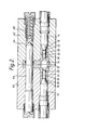
- Fig. 1 is an axial section of a connector assembly for optical fibres provided according to the principals of the method of the invention.
- Fig. 2 is an axial section on an enlarged scale of a portion of the connector assembly according to Fig. 1.
- Fig. 3 is an axial section of a portion of the connector assembly according to Fig. 1 and also including the portion thereof shown in Fig. 2 illustrating the conducting of the method according to the invention.
- Fig. 1 there is shown a connector assembly by means of which an end portion of a first optical fibre is connected with an end portion of a second optical fibre.
- the connector assembly shown in Fig. 1 comprises a first connector element 2 and a second connector element 4.
- the connector elements 2 and 4 are connected with each other by means of a conventional collar nut 6 which is rotatably connected with the connector element 4 and is threaded unto an outer thread of the connector element 2.
- a fibre cable 8 is connected with the connector element 2 and a fibre cable 10 is connected with the connector element 4.
- the fibre cables 8 and 10 constitute the two end portions of said first and said second optical fibres which are connected with each other by means of the connector assembly shown in Fig. 1.
- the connector assembly shown in Fig. 1 The connector assembly shown in Fig.
- the connector assembly can be constructed so as to provide connection of two or several pairs of end portions of optical fibres.
- the first optical fibre extends from the fibre cable 8 in a way not shown, to a sleeve shaped element 12 of the first connector element 2, while the second optical fibre extends from the fibre cable 10 in a way which is not shown in the drawing, to a sleeve shaped element 14 of the second connector element 4.
- the sleeve shaped elements 12 and 14 are of the kind shown and described in the Swedish patent No 426 882.
- each of the sleeve shaped elements 12 and 14 has an outer conical reference surface 16 and 18, respectively, the end portions of the optical fibres being centered in relation to the reference surfaces of the sleeve shaped elements 12 and 14.
- the conical reference surfaces 16 and 18 engage complementary, conical inner surfaces 20 and 22, respectively, of the connector element 24 and 26, respectively.
- a lense 28 and 30, respectively In each connector element 24 and 26 there is positioned a lense 28 and 30, respectively.
- the lenses 28 and 30 are connected with each of the connector elements 24 and 26 in such a way that the optical axes of the lenses are positioned exactly on the axes of the conical inner surfaces 20 and 22.
- each of the conical reference surfaces 16 and 18 engages one of the conical inner surfaces 20 and 22 and the end portions of the optical fibres and the lenses are centered in relation to said surfaces there is also provided a correct mutual relationship between the end portions of the optical fibres and the adjacent lense.
- the connector elements 24 and 26 are provided with transparent protecting elements 32 and 34.
- the connector elements 24 and 26 have substantially cylindrical outer surfaces 36 and 38 which are concentric with each of the conical inner surfaces 20 and 22 and each of the lenses 28 and 30.
- the cylindrical outer surfaces 36 and 38 engage with pressfit bores in insert portions 40 and 42.
- the insert portions 40 and 42 are correctly positioned in relation to each other by means of guide pins of which only one guide pin 44 is visible in Fig. 1.
- the guide pin 44 is fixed in the insert element 40 and engages a boring in the insert element 42 in order to provide the correct mutual. relationship between the insert portions 40 and 42.
- the guide pin 44 has a conical end portion 46 engaging a complementary conical recess in a resilient engagement element of the insert portion 42.
- Fig. 2 there is shown a cross-section on an enlarged scale of the insert portions 40 and 42 and the elements thereof described with reference to Fig. 1.
- the insert elements 40 and 42 are resiliently or in a floating way suspended in the connector elements 2 and 4 by means of 0-rings 50 and corrugated springs 52.
- Fig. 3 illustrates the method according to the invention for providing the correct position of the lense 28 in the connector element 24 in relation to the conical inner surface 20 and the cylindrical outer surface 36 of the connector element.
- the method of providing the correct positioning is valid also in respect of the connector element 26 and the lense 30 thereof.
- the connector element 24 is defined by the cylindrical inner surface 54 shown in broken lines instead of by the conical inner surface 20 and by the cylindrical outer surface 56 also shown in broken lines instead of the cylindrical outer surface 36.
- the connector element is connected with a retainer element 58.
- the retainer element 58 is rotatably supported in a working machine.
- the retainer element is supported in the working machine in such a way that the retainer element and thereby the connector element 24 are movable along two axes extending transversely of the rotation axis of the retainer element and the connector element so that the retainer element 58 and the connector element 24 can be adjusted to desired position in relation to said axis of rotation.
- Light is supplied to the lense 28 from the right in Fig. 3, the light beam leaving the lense from the left end surface 60 thereof in Fig. 3.
- the focus of the lense 28 thereby being positioned outside the lense to the left of the end surface 60.
- the light beam from the lense 28 is projected on a surface, for example the surface of a sensing device.
- the retainer element and therewith the connector element 24 are rotated, whereby it is possible to establish if the optical axis of the lense coincides with the rotational axis. If this is not the case the projection of the light beam will conduct a circular motion.
- the retainer element 58 with the connector element 24 is adjusted along the axes extending transversely of the rotational axis until the projection of the light beam is stationary, which means that the optical axis of the lense 28 coincides with the rotational axis.
- the surfaces 54 and 56 are thereupon machined while the retainer element 58 and the connector element 24 are rotated using the same rotational axis as previously used by means of turning. Thereby the conical inner surface 20 and the outer cylindrical surface 36 are formed in such a way that the axes of said surfaces will exactly coincide with the optical axis of the lense 28.
Landscapes
- Physics & Mathematics (AREA)
- General Physics & Mathematics (AREA)
- Optics & Photonics (AREA)
- Optical Couplings Of Light Guides (AREA)
- Mechanical Coupling Of Light Guides (AREA)
Priority Applications (1)
| Application Number | Priority Date | Filing Date | Title |
|---|---|---|---|
| AT86850201T ATE89667T1 (de) | 1986-03-19 | 1986-06-06 | Verfahren fuer die optische verbindung eines faserendes mit einem optischen element. |
Applications Claiming Priority (2)
| Application Number | Priority Date | Filing Date | Title |
|---|---|---|---|
| SE8601277A SE455542B (sv) | 1986-03-19 | 1986-03-19 | Sett for optisk anslutning av ett endparti av en optisk fiber till ett annat optiskt element |
| SE8601277 | 1986-03-19 |
Publications (3)
| Publication Number | Publication Date |
|---|---|
| EP0241630A2 true EP0241630A2 (de) | 1987-10-21 |
| EP0241630A3 EP0241630A3 (en) | 1989-08-23 |
| EP0241630B1 EP0241630B1 (de) | 1993-05-19 |
Family
ID=20363891
Family Applications (1)
| Application Number | Title | Priority Date | Filing Date |
|---|---|---|---|
| EP86850201A Expired - Lifetime EP0241630B1 (de) | 1986-03-19 | 1986-06-06 | Verfahren für die optische Verbindung eines Faserendes mit einem optischen Element |
Country Status (6)
| Country | Link |
|---|---|
| US (1) | US4884861A (de) |
| EP (1) | EP0241630B1 (de) |
| JP (1) | JPS62220909A (de) |
| AT (1) | ATE89667T1 (de) |
| DE (1) | DE3688464T2 (de) |
| SE (1) | SE455542B (de) |
Families Citing this family (10)
| Publication number | Priority date | Publication date | Assignee | Title |
|---|---|---|---|---|
| SE465098B (sv) * | 1989-04-25 | 1991-07-22 | Ericsson Telefon Ab L M | Kontaktdon |
| US5054879A (en) * | 1990-04-09 | 1991-10-08 | Mthode Electronics, Inc. | Push/pull fiber optic connector |
| US6280098B1 (en) | 1997-05-09 | 2001-08-28 | Point Source Limited | Optical fibre connector |
| GB9709479D0 (en) | 1997-05-09 | 1997-07-02 | Point Source Limited | Optical fibre connector |
| US7014369B2 (en) * | 2002-10-08 | 2006-03-21 | Point Source Limited | Optical fiber connector |
| US6913402B2 (en) * | 2003-08-07 | 2005-07-05 | Stratos International, Inc. | Bulkhead mountable optoelectronic device |
| US7220062B2 (en) * | 2005-02-28 | 2007-05-22 | Stratos International, Inc. | Active bulkhead transceiver |
| US7104701B1 (en) | 2005-02-28 | 2006-09-12 | Stratos International, Inc. | Expanded beam converter for MIL-PRF-83526/17 optical connector |
| US7350981B2 (en) * | 2006-05-09 | 2008-04-01 | Stratos International, Inc. | Fiber optic buildout converter, physical contact to expanded beam |
| US7766557B2 (en) * | 2007-03-06 | 2010-08-03 | Stratos International, Inc. | Expanded beam connector and expanded beam optoelectronic device |
Family Cites Families (14)
| Publication number | Priority date | Publication date | Assignee | Title |
|---|---|---|---|---|
| NL7806829A (nl) * | 1978-06-26 | 1979-12-28 | Philips Nv | Snel losneembare koppeling voor lichtgeleidende vezels. |
| NL181052C (nl) * | 1978-09-26 | 1987-06-01 | Philips Nv | Werkwijze en inrichting voor het voorzien in een concentrische omhulling op een uiteinde van een lichtgeleidende vezel. |
| US4215937A (en) * | 1979-01-29 | 1980-08-05 | International Telephone And Telegraph Corporation | Method and apparatus for detecting optimum alignment of optical fibers in a connector arrangement |
| JPS5824203B2 (ja) * | 1979-02-13 | 1983-05-19 | 日本電信電話株式会社 | 光フアイバコネクタ用プラグの製造方法 |
| DE2922937C2 (de) * | 1979-06-01 | 1981-07-02 | Fabeg Gmbh, 7518 Bretten | Kabelkupplung zum selbsttätigen Durchkuppeln elektrischer Heiz- und/oder Steuerstromleitungen sowie von Lichtleitern zur optischen Befehlsübertragung, insbesondere für Bahnfahrzeuge |
| EP0053914A1 (de) * | 1980-12-03 | 1982-06-16 | Combined Optical Industries Limited | Faseroptische Verbinder und Linsenelemente dafür |
| GB2089061B (en) * | 1980-12-04 | 1984-04-18 | Standard Telephones Cables Ltd | Optical fibre-beam expander alignment testing |
| SE8202359L (sv) * | 1981-04-20 | 1982-10-21 | Malco | Anordning for inbordes inriktning av en optisk fiber och en kollimatorlins |
| GB2145534B (en) * | 1983-08-22 | 1987-01-21 | Deutsch Co Elec Comp | Optical interconnection |
| US4733936A (en) * | 1985-06-28 | 1988-03-29 | Amphenol Corporation | Fiber optic connector assembly |
| US4718744A (en) * | 1985-08-16 | 1988-01-12 | Amp Incorporated | Collimating lens and holder for an optical fiber |
| US4691985A (en) * | 1985-09-23 | 1987-09-08 | Gte Products Corporation | Fiber optic connector |
| US4711518A (en) * | 1985-11-25 | 1987-12-08 | Gte Products Corporation | Fiber optic connector |
| US4770488A (en) * | 1985-12-18 | 1988-09-13 | Gte Service Corporation | Fiber optical connector with lens |
-
1986
- 1986-03-19 SE SE8601277A patent/SE455542B/sv not_active IP Right Cessation
- 1986-06-06 EP EP86850201A patent/EP0241630B1/de not_active Expired - Lifetime
- 1986-06-06 AT AT86850201T patent/ATE89667T1/de not_active IP Right Cessation
- 1986-06-06 DE DE8686850201T patent/DE3688464T2/de not_active Expired - Fee Related
- 1986-07-03 JP JP61155224A patent/JPS62220909A/ja active Pending
-
1988
- 1988-02-05 US US07/154,507 patent/US4884861A/en not_active Expired - Fee Related
Also Published As
| Publication number | Publication date |
|---|---|
| JPS62220909A (ja) | 1987-09-29 |
| US4884861A (en) | 1989-12-05 |
| DE3688464T2 (de) | 1993-08-26 |
| ATE89667T1 (de) | 1993-06-15 |
| SE455542B (sv) | 1988-07-18 |
| SE8601277D0 (sv) | 1986-03-19 |
| SE8601277L (sv) | 1987-09-20 |
| EP0241630B1 (de) | 1993-05-19 |
| DE3688464D1 (de) | 1993-06-24 |
| EP0241630A3 (en) | 1989-08-23 |
Similar Documents
| Publication | Publication Date | Title |
|---|---|---|
| EP0205984B1 (de) | Endstück für optische Faser und Verfahren zur Herstellung | |
| EP0519219B1 (de) | Vorrichtung zum optischen Verbinden eines optischen Elements, zum Beispiel einer optischen Faser, mit einer Linse | |
| US5257332A (en) | Optical fiber expanded beam coupler | |
| US5682452A (en) | Optical fiber ferrule and optical coupler | |
| US4884861A (en) | Method of optical connection of an end portion of an optical fibre with an other optical element | |
| US5351334A (en) | Rotation and alignment device for assembling of optical fiber connector with lower connection loss | |
| EP0051915B1 (de) | Optischer Verbinder und den Verbinder enthaltende optische Verbindung | |
| CA2172749C (en) | Device for optical connection of an optical element, for example an optical fibre, with a lens | |
| GB2033104A (en) | Aligning optic fibre and its ferrule | |
| EP0278507B1 (de) | Optisches Halbleitermodul | |
| US4636030A (en) | Optical alignment apparatus utilizing prismatic elements | |
| HK2389A (en) | Connector for optical fibres and method for its manufacture | |
| GB2210994A (en) | Optical fibre connector having a longitudinally movable sleeve | |
| CA2262351A1 (en) | Tunable multiple fiber optical connector | |
| GB2315564A (en) | Optical device having slant end surfaced optic fibre and GRIN lens | |
| EP0125829A2 (de) | Optische Verbinder | |
| EP0598328A1 (de) | Faseroptische Justiervorrichtung | |
| US4892380A (en) | Optical connector | |
| GB2062891A (en) | Fiber optic connector for high density applications and method of manufacturing fiber optic connectors | |
| US7048446B2 (en) | Connector for impact mounted bundled optical fiber devices | |
| CA2239561C (en) | A device for optical connection of an optical fibre, with another optical element | |
| JPS60216316A (ja) | 光フアイバコネクタ | |
| KR920010262A (ko) | 광커넥터의 치수측정방법 | |
| SU1765796A1 (ru) | Способ изготовлени оптического соединител | |
| JPH03145607A (ja) | 単心光コネクタ |
Legal Events
| Date | Code | Title | Description |
|---|---|---|---|
| PUAI | Public reference made under article 153(3) epc to a published international application that has entered the european phase |
Free format text: ORIGINAL CODE: 0009012 |
|
| AK | Designated contracting states |
Kind code of ref document: A2 Designated state(s): AT BE CH DE FR GB IT LI NL |
|
| PUAL | Search report despatched |
Free format text: ORIGINAL CODE: 0009013 |
|
| AK | Designated contracting states |
Kind code of ref document: A3 Designated state(s): AT BE CH DE FR GB IT LI NL |
|
| 17P | Request for examination filed |
Effective date: 19900220 |
|
| 17Q | First examination report despatched |
Effective date: 19910911 |
|
| RAP1 | Party data changed (applicant data changed or rights of an application transferred) |
Owner name: AB STRATOS CONNECTORS |
|
| ITF | It: translation for a ep patent filed | ||
| GRAA | (expected) grant |
Free format text: ORIGINAL CODE: 0009210 |
|
| AK | Designated contracting states |
Kind code of ref document: B1 Designated state(s): AT BE CH DE FR GB IT LI NL |
|
| REF | Corresponds to: |
Ref document number: 89667 Country of ref document: AT Date of ref document: 19930615 Kind code of ref document: T |
|
| ET | Fr: translation filed | ||
| REF | Corresponds to: |
Ref document number: 3688464 Country of ref document: DE Date of ref document: 19930624 |
|
| PLBE | No opposition filed within time limit |
Free format text: ORIGINAL CODE: 0009261 |
|
| STAA | Information on the status of an ep patent application or granted ep patent |
Free format text: STATUS: NO OPPOSITION FILED WITHIN TIME LIMIT |
|
| 26N | No opposition filed | ||
| PGFP | Annual fee paid to national office [announced via postgrant information from national office to epo] |
Ref country code: FR Payment date: 19940520 Year of fee payment: 9 |
|
| PGFP | Annual fee paid to national office [announced via postgrant information from national office to epo] |
Ref country code: DE Payment date: 19940525 Year of fee payment: 9 |
|
| PGFP | Annual fee paid to national office [announced via postgrant information from national office to epo] |
Ref country code: GB Payment date: 19940527 Year of fee payment: 9 |
|
| PGFP | Annual fee paid to national office [announced via postgrant information from national office to epo] |
Ref country code: AT Payment date: 19940531 Year of fee payment: 9 |
|
| PGFP | Annual fee paid to national office [announced via postgrant information from national office to epo] |
Ref country code: BE Payment date: 19940608 Year of fee payment: 9 |
|
| PGFP | Annual fee paid to national office [announced via postgrant information from national office to epo] |
Ref country code: CH Payment date: 19940623 Year of fee payment: 9 |
|
| PGFP | Annual fee paid to national office [announced via postgrant information from national office to epo] |
Ref country code: NL Payment date: 19940630 Year of fee payment: 9 |
|
| PG25 | Lapsed in a contracting state [announced via postgrant information from national office to epo] |
Ref country code: GB Effective date: 19950606 Ref country code: AT Effective date: 19950606 |
|
| PG25 | Lapsed in a contracting state [announced via postgrant information from national office to epo] |
Ref country code: LI Effective date: 19950630 Ref country code: CH Effective date: 19950630 Ref country code: BE Effective date: 19950630 |
|
| BERE | Be: lapsed |
Owner name: STRATOS CONNECTORS A.B. Effective date: 19950630 |
|
| PG25 | Lapsed in a contracting state [announced via postgrant information from national office to epo] |
Ref country code: NL Effective date: 19960101 |
|
| GBPC | Gb: european patent ceased through non-payment of renewal fee |
Effective date: 19950606 |
|
| PG25 | Lapsed in a contracting state [announced via postgrant information from national office to epo] |
Ref country code: FR Effective date: 19960229 |
|
| REG | Reference to a national code |
Ref country code: CH Ref legal event code: PL |
|
| NLV4 | Nl: lapsed or anulled due to non-payment of the annual fee |
Effective date: 19960101 |
|
| PG25 | Lapsed in a contracting state [announced via postgrant information from national office to epo] |
Ref country code: DE Effective date: 19960301 |
|
| REG | Reference to a national code |
Ref country code: FR Ref legal event code: ST |
|
| PG25 | Lapsed in a contracting state [announced via postgrant information from national office to epo] |
Ref country code: IT Free format text: LAPSE BECAUSE OF NON-PAYMENT OF DUE FEES;WARNING: LAPSES OF ITALIAN PATENTS WITH EFFECTIVE DATE BEFORE 2007 MAY HAVE OCCURRED AT ANY TIME BEFORE 2007. THE CORRECT EFFECTIVE DATE MAY BE DIFFERENT FROM THE ONE RECORDED. Effective date: 20050606 |