EP0241660A2 - Plaque de base pour la fixation d'un bras de charnière d'une charnière pour meubles ou similaires - Google Patents
Plaque de base pour la fixation d'un bras de charnière d'une charnière pour meubles ou similaires Download PDFInfo
- Publication number
- EP0241660A2 EP0241660A2 EP87101856A EP87101856A EP0241660A2 EP 0241660 A2 EP0241660 A2 EP 0241660A2 EP 87101856 A EP87101856 A EP 87101856A EP 87101856 A EP87101856 A EP 87101856A EP 0241660 A2 EP0241660 A2 EP 0241660A2
- Authority
- EP
- European Patent Office
- Prior art keywords
- base plate
- base
- cover plate
- plate according
- bores
- Prior art date
- Legal status (The legal status is an assumption and is not a legal conclusion. Google has not performed a legal analysis and makes no representation as to the accuracy of the status listed.)
- Granted
Links
Images

Classifications
-
- E—FIXED CONSTRUCTIONS
- E05—LOCKS; KEYS; WINDOW OR DOOR FITTINGS; SAFES
- E05D—HINGES OR SUSPENSION DEVICES FOR DOORS, WINDOWS OR WINGS
- E05D5/00—Construction of single parts, e.g. the parts for attachment
- E05D5/02—Parts for attachment, e.g. flaps
- E05D5/0276—Parts for attachment, e.g. flaps for attachment to cabinets or furniture, the hinge having two or more pins
-
- E—FIXED CONSTRUCTIONS
- E05—LOCKS; KEYS; WINDOW OR DOOR FITTINGS; SAFES
- E05D—HINGES OR SUSPENSION DEVICES FOR DOORS, WINDOWS OR WINGS
- E05D7/00—Hinges or pivots of special construction
- E05D7/04—Hinges adjustable relative to the wing or the frame
- E05D7/0407—Hinges adjustable relative to the wing or the frame the hinges having two or more pins and being specially adapted for cabinets or furniture
-
- A—HUMAN NECESSITIES
- A47—FURNITURE; DOMESTIC ARTICLES OR APPLIANCES; COFFEE MILLS; SPICE MILLS; SUCTION CLEANERS IN GENERAL
- A47B—TABLES; DESKS; OFFICE FURNITURE; CABINETS; DRAWERS; GENERAL DETAILS OF FURNITURE
- A47B2230/00—Furniture jointing; Furniture with such jointing
- A47B2230/11—Attachment fittings mounted in blind holes
-
- E—FIXED CONSTRUCTIONS
- E05—LOCKS; KEYS; WINDOW OR DOOR FITTINGS; SAFES
- E05Y—INDEXING SCHEME ASSOCIATED WITH SUBCLASSES E05D AND E05F, RELATING TO CONSTRUCTION ELEMENTS, ELECTRIC CONTROL, POWER SUPPLY, POWER SIGNAL OR TRANSMISSION, USER INTERFACES, MOUNTING OR COUPLING, DETAILS, ACCESSORIES, AUXILIARY OPERATIONS NOT OTHERWISE PROVIDED FOR, APPLICATION THEREOF
- E05Y2900/00—Application of doors, windows, wings or fittings thereof
- E05Y2900/20—Application of doors, windows, wings or fittings thereof for furniture, e.g. cabinets
-
- Y—GENERAL TAGGING OF NEW TECHNOLOGICAL DEVELOPMENTS; GENERAL TAGGING OF CROSS-SECTIONAL TECHNOLOGIES SPANNING OVER SEVERAL SECTIONS OF THE IPC; TECHNICAL SUBJECTS COVERED BY FORMER USPC CROSS-REFERENCE ART COLLECTIONS [XRACs] AND DIGESTS
- Y10—TECHNICAL SUBJECTS COVERED BY FORMER USPC
- Y10S—TECHNICAL SUBJECTS COVERED BY FORMER USPC CROSS-REFERENCE ART COLLECTIONS [XRACs] AND DIGESTS
- Y10S16/00—Miscellaneous hardware, e.g. bushing, carpet fastener, caster, door closer, panel hanger, attachable or adjunct handle, hinge, window sash balance
- Y10S16/43—Hinge mounting bracket
Definitions
- the invention relates to a base plate for fastening a hinge arm of a furniture hinge or the like, consisting of a or the like on a support wall. by fastening screws attachable base plate and an at least partially overlapping or overlapping and on this or the like across the hinge arm. Slidably guided cover plate with fastening devices for the hinge arm.
- a base plate of this type known from DE-OS 3 0 22 44o which in particular enables adjustment at the height of the furniture, consists of a base plate provided on one side with opposing strip-shaped projections, on one side of which the cover plate provided with corresponding complementary grooves can be postponed while the other
- the object of the invention is therefore to provide a base plate of the type mentioned, the cover plate is displaceable relative to the base plate with simple means so that it can be produced in the economic manner required for a mass product.
- this object is achieved with a base plate of the generic type in that the base plate is provided in the region of its ends with holes for fastening screws which are aligned with the central regions of elongated holes lying on their common connecting line in lateral tab-shaped extensions of the cover plate and in that the holes are at least partially surrounded by bases which form guides for the flanks of the elongated holes.
- the cover plate for the transverse displacement of the hinge arm or the like can be moved relative to the base plate in the desired manner until the cover plate is clamped to the base plate by means of fastening or clamping screws for final fixing.
- the collar-shaped bases pass through the cover plate supported on the base plate in the elongated holes and protrude above the tops of the extensions, the cover plate or one of its extensions being provided with a third elongated hole parallel to the elongated holes, the a screwed into a threaded hole in the base plate and provided with a head screw.
- the base plate is fastened to a supporting wall or the like in that the heads of the screwed-in fastening screws on the holes at least partially surrounding the holes in the base plate support base-like projections.
- the cover plate Since the base-like protrusions protrude beyond the oblong holes of the cover plate, the cover plate is still held on the base plate after it has been fastened by the fastening screws.
- the cover plate carrying the hinge arm or the like can therefore be aligned relative to the base plate after the base plate has been fastened, for example to adjust the height of a hinge, the cover plate then being fixed on the base plate by tightening the clamping screws the clamping screws are fixed in their middle position on the base plate, so that after mounting the base plate it is only necessary to loosen the clamping screw and align the cover plate if necessary.
- the width of the base expediently corresponds to the width of the elongated holes, so that the cover plate is guided in the elongated holes on the bases.
- the bases can only be provided on opposite sides of the holes in the base plate in the elongated holes, the width of the bases corresponding to the diameter of the holes in the base plate.
- the base plate can be essentially rectangular and the cover plate can be cross-shaped.
- the cover plate is expediently designed to be symmetrical with respect to its longitudinal center line, so that the hinge arm can be attached to the cantilever to the left or right.
- the cover plate can be provided on its underside with a transverse groove-shaped recess, the end regions of which lie in the lateral extensions, the cover plate being guided with the flanks of the recess on the side edges of the essentially rectangular base plate. With this Ausge staltung the cover plate is not guided by the base-like projections, but on the side flanks of the base plate.
- a base is of such a shorter design that it ends in one of the elongated holes below its upper edge.
- the hinge arm which is screwed into the hole with the shorter base attachment screw can be solved, so that the transverse movement possible ist.-to fix the cover plate must then corresponds s p computing fixing screw to be screwed again.
- the fastening screw used for the adjustment is expediently indicated by an arrow.
- the bases only partially penetrate the oblong holes in the cover plate.
- the base plate is already fixed by this substantially against displacements in the longitudinal and transverse directions before the fastening screws are fully tightened, so that the cover plate carrying the hinge arm can be displaced in the transverse direction of the hinge arm to adjust it on the base plate. whereby the base framed by the elongated holes take over an exact guidance.
- the base plate can be fixed in position by completely tightening the fastening screws. Since the base plate of the base plate, which only serves as a guide, does not completely penetrate the elongated holes, there is between the top sides the guide base and the cover plate have sufficient play to tighten the cover plate using the fastening screws.
- Base plates for fastening hinge arms or the like are already known, which consist of die-cast zamak. Such base plates have rectangular groove-like recesses which extend transversely to the central part which serves to fasten the hinge arm into the lateral, flap-like conveying sets which serve to fasten them, and thereby serve to guide the rectangular base plates which are enclosed by them, with their sides on the inner lateral flanks of the groove-shaped recesses provided on the undersides of the cover plates.
- Die-cast base or cover plates are relatively expensive.
- the design of a base plate according to the invention enables the cover plate to be made of sheet steel. A cover plate produced as a stamped part from sheet steel cannot usually be manufactured so precisely that it has groove-like guides for a base plate on its underside. Since in the base plate according to the invention the cover plate is guided on the base plate in elongated holes in the cover plate which enclose base-like projections of the base plate, the invention enables the cover plate to be produced without problems from a sheet steel stamped part.
- the tab-shaped extensions are expediently provided with circumferential edges which are angled downward in the manner of a leg for reinforcement purposes.
- the cover plate can expediently also the base overlap plate so that it is not visible when assembled. The thickness of the base plate is therefore less than the height of the downwardly angled edges of the cover plate.
- the U-shaped angled edges surrounding the extensions open into parallel, downwardly angled lateral edges of the middle part of the cover plate which serves to fasten the hinge arm over rounded angular areas.
- the bases advantageously have a rectangular shape in plan view.
- the base plate is made of plastic and the bases are held with a press fit in the central region of the elongated holes. This configuration enables normal mounting of the base plate in its central position, so that an adjustment need only be made if this should be necessary in exceptional cases.
- the base plate is expediently provided on its underside in one piece with dowels surrounding the bores, which are used to fix the base plate even before the fastening screws are tightened in the fastening bores.
- the base plate in the region of the base is provided with a bore section whose diameter corresponds at least to the diameter of the thread of the fastening screw.
- the bore in the base plate has a section with a diameter which is smaller than the diameter of the thread of the fastening screw.
- the section of the bore with the smaller diameter used for the preassembly of the fastening screw is expediently located in the region of the plane of the base plate.
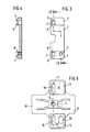
- the base plate 1 has a substantially rectangular shape.
- the base plate which, like the cover plate, is made of die-cast zinc or the like. can be produced, has thicker end regions 2 than the central region. These end areas are provided off-center symmetrically to the transverse center line with holes 3 for the fastening screws 4.
- the bores 3 are provided on their inwardly and outwardly facing sides with these partially enclosing base-like projections 5, 6, the width of which essentially corresponds to the diameter of the bores 3, 4.
- a single one lying only on one side of the bore could also be provided.
- One side of the base plate 1 is additionally provided with a threaded bore 7 for the clamping screw 8.
- the cover plate 10 has on its upper side an H-shaped base-like projection 11 with a central threaded bore 12 for holding the hinge arm 25.
- the cover plate 10 is wing-like with lateral extensions 13, 14, which have elongated holes 15, 16, which are on a common transverse center line 17 of the middle part 18, which is provided with the mounting base 11, lie.
- the cover plate 10 is provided on its underside in the side flight-like extensions 13 with a recess indicated by dashed lines 20, into which the base plate 1 can be fitted.
- the side flanks of the recess of the cover plate lie on the side edges of the Bssisolatte 2 with play, while the length of the recess is greater than the length of the base plate, so that the cover plate 10 is displaceable on the base plate 2.
- the base-like projections 5, 6 lie in the elongated holes 15, 16 and penetrate them in such a way that the upper end faces of the base-like projections lie above the undersides of the wing-like extensions 13, 14.
- Fig. 1 the hinge arm 13 can be seen in its assembled position.
- the base plate 1 is fixed on the furniture side wall 24 by the fastening screws 4. To make a height adjustment, it is only necessary to loosen the clamping screw 8 and tighten it again after the corresponding displacement of the cover plate 10.
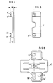
- the embodiment according to FIGS. 6 to 8 differs from that in that the clamping screw 8 with the third elongated hole 2b and the threaded hole is omitted 7 of FIGS. 1 D is 5 characterized and instead the height of the pedestal-like Vorspringe 27, 28 is reduced so that they do not penetrate the elongated hole lo ', while the height of the base-like projections 5', 6 'corresponds to the height of the base-like projections of the base plate of the previously described embodiment.
- the height h of the base-like projections 27, 28 is therefore less than the height H of the base-like projections 5 ', 6.
- the cover plate 10' in the wing-shaped extension 14 ' is the elongated hole 16', to which the shorter base-like projections 27, 23 are assigned are marked by the arrow, so that the honter immediately recognizes Which of the two fastening screws is used to clamp the cover plate 10 'on the base plate 1'. Should a height adjustment be necessary after the installation of the fastening plate according to the exemplary embodiment in FIGS. 6 to 8, this is the elongated hole 16 'and the hole 3' of the base plate '' Loosen the penetrating fastening screw and tighten it again after adjustment.
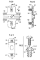
- the base plate 10 consists of a base plate 102 which is rectangular in plan view with rounded corners and a cover plate 103 which completely overlaps it.
- the cover plate lo3 consists of a stamped part made of sheet steel and has a central, U-shaped profiled region 104 which serves to hold the usually U-shaped profiled arm arm.
- the hinge arm not shown, overlaps with its side legs the fastening base 1 0 4 formed by the U-shaped profile, which is provided in its central region with a threaded bore 150 which serves to screw in the fastening screw for the hinge arm.
- the central middle part of the cover plate which forms a fastening profile 104, is connected to lateral flange-like tabs 105, lo6, or the like for fastening the base plate or the fastening plate lo3 to a supporting wall. serve.
- These lateral tab-like extensions are provided with a circumferential, downwardly flanged edge 107, 1 0 8, which continues over the adjacent lateral areas 109, 110, 111, 112 of the central part.
- the cover plate 103 is formed symmetrically to its longitudinal center line and to its transverse center line II-II, so that the Base plate lol suitable for both right and left hinging of a joint.
- the cover plate lo3 is provided in its lateral tab-like extensions 105, 106 with elongated holes 115, 116, the center lines of which are aligned with the transverse center line II - II.
- the base plate LO2 has a substantially rectangular shape and is engaged over in the of FIG. 1 0 manner shown by the beaded edges lo7, 108 of the tab-like extensions 105, 106 of the cover plate 103.
- the base plate is provided with bores 12 0 , 121 lying on its longitudinal center line, which are used to hold fastening screws 123.
- the bores 12 0 , 121 are surrounded by base-like elevations 122, 123, which are rectangular in plan view and in the assembled state are bordered on their sides by the flanks of the elongated holes 115, 116 of the cover plate lo3.
- the bases 122, 123 have a height that is less than the thickness of the sheet of the cover plate 1 03 , so that these do not penetrate the elongated holes 115, 116.
- the length of the base 122, 123 is smaller than the elongated holes 115, 116, as can be seen in FIGS. 9 and 10, so that the cover plate 103 can be displaced on the base plate 102 along the transverse center line II-II Side flanks of the elongated holes 115, 116 adjacent sides of the base 122, 123 take over an exact guidance.
- the base plate 102 ends at a distance from the flanged edges 107, 108 of the cover plate 103. Since the cover plate 103 is guided on the base-like projections 122, 123 of the base plate 102, there is between the sides the base plate lo2 and the lateral flanged edges of the tab-like extensions 105, 106 of the cover plate 103 a game is provided.
- the base plate 102 has a central region 125 of smaller thickness and end regions 126, 127 of greater thickness.
- the regions 126, 127 of greater thickness of the base plate lo2 are also lower than the height of the flanged edges 1 07 , lo8 of the lateral tab-like extensions of the cover plate 103, so that the base plate lo2 is completely removed from the tab-like extensions 105 in the manner shown in FIG. 10 , lo6 of the cover plate lo3 is overlapped.
- the underside of the base plate lo2 is provided in the region of the bores 120, 121 with dowels 13o, the center lines of which are aligned with the center lines of the bores.
- the dowels are provided in a known manner with opposite longitudinal slots and on their outer surface with a sawtooth-shaped profile.
- 123 In the area of the base 122, 123 have the bores 12 0, 121 portions 131 having a diameter which is at least as large as the diameter of the thread and the fixing screws 151. On this bore portion 131 closes over a stage, a bore section 132 with lower Diameter into which the thread of the fastening screws 123 can cut for preassembly.
Landscapes
- Engineering & Computer Science (AREA)
- Mechanical Engineering (AREA)
- Hinges (AREA)
Priority Applications (1)
| Application Number | Priority Date | Filing Date | Title |
|---|---|---|---|
| AT87101856T ATE57229T1 (de) | 1986-02-17 | 1987-02-11 | Grundplatte zur befestigung eines scharnierarms eines moebelscharniers o. dgl. |
Applications Claiming Priority (4)
| Application Number | Priority Date | Filing Date | Title |
|---|---|---|---|
| DE19863604984 DE3604984A1 (de) | 1986-02-17 | 1986-02-17 | Grundplatte zur befestigung eines scharnierarms eines moebelscharniers o.dgl. |
| DE3604984 | 1986-02-17 | ||
| DE8620441U | 1986-07-30 | ||
| DE19868620441 DE8620441U1 (de) | 1986-07-30 | 1986-07-30 | Grundplatte zur Befestigung eines Scharnierarms eines Möbelscharniers od.dgl. |
Publications (3)
| Publication Number | Publication Date |
|---|---|
| EP0241660A2 true EP0241660A2 (fr) | 1987-10-21 |
| EP0241660A3 EP0241660A3 (en) | 1987-11-25 |
| EP0241660B1 EP0241660B1 (fr) | 1990-10-03 |
Family
ID=25841045
Family Applications (1)
| Application Number | Title | Priority Date | Filing Date |
|---|---|---|---|
| EP87101856A Expired - Lifetime EP0241660B1 (fr) | 1986-02-17 | 1987-02-11 | Plaque de base pour la fixation d'un bras de charnière d'une charnière pour meubles ou similaires |
Country Status (5)
| Country | Link |
|---|---|
| US (1) | US4800625A (fr) |
| EP (1) | EP0241660B1 (fr) |
| AT (1) | ATE57229T1 (fr) |
| DE (1) | DE3765283D1 (fr) |
| ES (1) | ES2018659B3 (fr) |
Families Citing this family (13)
| Publication number | Priority date | Publication date | Assignee | Title |
|---|---|---|---|---|
| DE3841933A1 (de) * | 1988-12-13 | 1990-06-21 | Salice Arturo Spa | Grundplatte zur befestigung eines moebelscharniers o. dgl. |
| US5083847A (en) * | 1991-01-28 | 1992-01-28 | Transfer Flow International, Inc. | Pocket door attachment fitting for a cabinet |
| DE4134828C2 (de) * | 1991-10-22 | 2001-11-15 | Lautenschlaeger Mepla Werke | Montageplatte für Möbelscharniere |
| US5345654A (en) * | 1992-12-21 | 1994-09-13 | Franco Ferrari | Quick-coupling wing type hinge and base |
| DE4342744A1 (de) * | 1993-12-15 | 1995-06-22 | Lautenschlaeger Mepla Werke | Möbelscharnier |
| DE4343805C2 (de) * | 1993-12-22 | 2002-11-21 | Lautenschlaeger Mepla Werke | Möbelscharnier mit Schnellmontage-Scharniertopf |
| DE29508286U1 (de) * | 1995-05-18 | 1995-08-24 | Arturo Salice S.P.A., Novedrate, Como | Montageplattenpaar zur Befestigung von Scharnierarmen von Möbelscharnieren o.dgl. |
| IT241033Y1 (it) * | 1996-11-29 | 2001-04-20 | Salice Arturo Spa | Piastra di base con dispositivo semplificato di regolazione per ilfissaggio di una cerniera per mobili |
| DE29813447U1 (de) | 1998-07-28 | 1998-11-05 | Salice Arturo Spa | Befestigungsplatte zur Befestigung eines Beschlagteils, z.B. eines Scharnierarms an einer Tragwand |
| DE20009317U1 (de) * | 2000-05-24 | 2000-08-17 | Arturo Salice S.P.A., Novedrate, Como | Befestigungsplatte zur Befestigung eines Scharnierarmes eines Möbelscharniers |
| DE20105841U1 (de) * | 2001-04-03 | 2001-06-21 | Hettich-ONI GmbH & Co. KG, 32602 Vlotho | Befestigungsplatte zur Befestigung eines Möbelbeschlages, z.B. eines Scharnierarmes eines Möbelscharnieres |
| DE20120238U1 (de) * | 2001-12-14 | 2003-04-24 | Lautenschlaeger Mepla Werke | Montageplatte zur verstellbaren Halterung von Möbelscharnieren am Korpus von Möbelstücken |
| US6647591B1 (en) * | 2002-07-01 | 2003-11-18 | Grass America Inc. | Low profile, partial door overlay hinge |
Family Cites Families (7)
| Publication number | Priority date | Publication date | Assignee | Title |
|---|---|---|---|---|
| DE2043622C3 (de) * | 1970-09-03 | 1981-09-10 | Karl Lautenschläger KG, Möbelbeschlagfabrik, 6107 Reinheim | Montageplatte für Möbelscharnier |
| FR2307107A1 (fr) * | 1975-04-07 | 1976-11-05 | Blum Gmbh Julius | Charniere |
| DE2601809C3 (de) * | 1976-01-20 | 1981-03-12 | SieMatic Möbelwerke August Siekmann KG, 4972 Löhne | Scharnier, insbesonder für Möbel |
| AT353131B (de) * | 1976-04-27 | 1979-10-25 | Blum Gmbh Julius | Vorrichtung zur hoeheneinstellung eines tiefen- einstellbaren scharniers mit einer grundplatte und einem zwischenstueck |
| DE2624453C2 (de) * | 1976-06-01 | 1986-10-16 | Karl Lautenschläger GmbH & Co KG Möbelbeschlagfabrik, 6107 Reinheim | Montageplatte für Möbelscharniere |
| AT348892B (de) * | 1976-11-30 | 1979-03-12 | Blum Gmbh Julius | Verstellbare, insbesondere hoehenverstellbare grundplatte, insbesondere fuer scharniere |
| AT368238B (de) * | 1979-07-02 | 1982-09-27 | Blum Gmbh Julius | Mehrteilige grundplatte mit einer einrichtung zum hoehenverstellen fuer moebelscharniere |
-
1987
- 1987-02-11 DE DE8787101856T patent/DE3765283D1/de not_active Expired - Fee Related
- 1987-02-11 AT AT87101856T patent/ATE57229T1/de not_active IP Right Cessation
- 1987-02-11 EP EP87101856A patent/EP0241660B1/fr not_active Expired - Lifetime
- 1987-02-11 ES ES87101856T patent/ES2018659B3/es not_active Expired - Lifetime
- 1987-02-13 US US07/014,399 patent/US4800625A/en not_active Expired - Fee Related
Also Published As
| Publication number | Publication date |
|---|---|
| EP0241660A3 (en) | 1987-11-25 |
| DE3765283D1 (de) | 1990-11-08 |
| ATE57229T1 (de) | 1990-10-15 |
| US4800625A (en) | 1989-01-31 |
| EP0241660B1 (fr) | 1990-10-03 |
| ES2018659B3 (es) | 1991-05-01 |
Similar Documents
| Publication | Publication Date | Title |
|---|---|---|
| DE3841933C2 (fr) | ||
| EP0241660B1 (fr) | Plaque de base pour la fixation d'un bras de charnière d'une charnière pour meubles ou similaires | |
| EP0894929B1 (fr) | Plaque de montage pour une ferrure, en particulier pour la fixation d'un bras de charnière sur une paroi de meuble | |
| DE3501048C2 (fr) | ||
| DE3605902C2 (fr) | ||
| EP0466289B1 (fr) | Agencement de charnière pour la porte d'une armoire de commutation | |
| EP0538591B1 (fr) | Plaque de montage pour charnières de meubles | |
| DE3444851C2 (fr) | ||
| CH625306A5 (fr) | ||
| EP0065310B1 (fr) | Système magnétique pour un relais | |
| DE3245056A1 (de) | Elastische klemme | |
| EP0256376B1 (fr) | Bras de charnière pour une charnière de meuble | |
| DE3610102A1 (de) | Viergelenk-moebelscharnier | |
| EP0274552A1 (fr) | Charnière visible de l'extérieur à ouverture à 180 degrés | |
| DE3604984C2 (fr) | ||
| DE2718402A1 (de) | Griff, insbesondere haltegriff fuer fahrzeuge | |
| DE8620441U1 (de) | Grundplatte zur Befestigung eines Scharnierarms eines Möbelscharniers od.dgl. | |
| DE2727962B2 (de) | Möbel-Beschlagteil | |
| DE2744052A1 (de) | Beschlag fuer tueren und waende aus glas | |
| EP0105395A2 (fr) | Dispositif de liaison de panneaux perpendiculaires de meuble | |
| DE2736333A1 (de) | Moebelscharnier | |
| DE4233402C2 (de) | Befestigungsvorrichtung für Schienen mit Reihen von Durchbrüchen und Bohrungen | |
| DE2638585A1 (de) | Rechteckfoermige grund- oder verstellplatte fuer moebelscharniere | |
| EP0387391A1 (fr) | Plaque de montage pour la fixation d'un bras de charnière d'une charnière de meubles | |
| EP0464624B1 (fr) | Embase pour fixations de ski |
Legal Events
| Date | Code | Title | Description |
|---|---|---|---|
| PUAI | Public reference made under article 153(3) epc to a published international application that has entered the european phase |
Free format text: ORIGINAL CODE: 0009012 |
|
| PUAL | Search report despatched |
Free format text: ORIGINAL CODE: 0009013 |
|
| AK | Designated contracting states |
Kind code of ref document: A2 Designated state(s): AT DE ES FR GB IT |
|
| AK | Designated contracting states |
Kind code of ref document: A3 Designated state(s): AT DE ES FR GB IT |
|
| 17P | Request for examination filed |
Effective date: 19880510 |
|
| 17Q | First examination report despatched |
Effective date: 19890601 |
|
| GRAA | (expected) grant |
Free format text: ORIGINAL CODE: 0009210 |
|
| AK | Designated contracting states |
Kind code of ref document: B1 Designated state(s): AT DE ES FR GB IT |
|
| REF | Corresponds to: |
Ref document number: 57229 Country of ref document: AT Date of ref document: 19901015 Kind code of ref document: T |
|
| GBT | Gb: translation of ep patent filed (gb section 77(6)(a)/1977) | ||
| REF | Corresponds to: |
Ref document number: 3765283 Country of ref document: DE Date of ref document: 19901108 |
|
| ET | Fr: translation filed | ||
| ITF | It: translation for a ep patent filed | ||
| PGFP | Annual fee paid to national office [announced via postgrant information from national office to epo] |
Ref country code: GB Payment date: 19910125 Year of fee payment: 5 |
|
| PGFP | Annual fee paid to national office [announced via postgrant information from national office to epo] |
Ref country code: FR Payment date: 19910208 Year of fee payment: 5 |
|
| ITTA | It: last paid annual fee | ||
| PLBE | No opposition filed within time limit |
Free format text: ORIGINAL CODE: 0009261 |
|
| STAA | Information on the status of an ep patent application or granted ep patent |
Free format text: STATUS: NO OPPOSITION FILED WITHIN TIME LIMIT |
|
| 26N | No opposition filed | ||
| PGFP | Annual fee paid to national office [announced via postgrant information from national office to epo] |
Ref country code: AT Payment date: 19920128 Year of fee payment: 6 |
|
| PG25 | Lapsed in a contracting state [announced via postgrant information from national office to epo] |
Ref country code: GB Effective date: 19920211 |
|
| PGFP | Annual fee paid to national office [announced via postgrant information from national office to epo] |
Ref country code: ES Payment date: 19920217 Year of fee payment: 6 |
|
| PGFP | Annual fee paid to national office [announced via postgrant information from national office to epo] |
Ref country code: DE Payment date: 19920228 Year of fee payment: 6 |
|
| GBPC | Gb: european patent ceased through non-payment of renewal fee | ||
| PG25 | Lapsed in a contracting state [announced via postgrant information from national office to epo] |
Ref country code: FR Effective date: 19921030 |
|
| REG | Reference to a national code |
Ref country code: FR Ref legal event code: ST |
|
| PG25 | Lapsed in a contracting state [announced via postgrant information from national office to epo] |
Ref country code: AT Effective date: 19930211 |
|
| PG25 | Lapsed in a contracting state [announced via postgrant information from national office to epo] |
Ref country code: ES Free format text: LAPSE BECAUSE OF NON-PAYMENT OF DUE FEES Effective date: 19930212 |
|
| PG25 | Lapsed in a contracting state [announced via postgrant information from national office to epo] |
Ref country code: DE Effective date: 19931103 |
|
| REG | Reference to a national code |
Ref country code: ES Ref legal event code: FD2A Effective date: 19990201 |
|
| PG25 | Lapsed in a contracting state [announced via postgrant information from national office to epo] |
Ref country code: IT Free format text: LAPSE BECAUSE OF NON-PAYMENT OF DUE FEES;WARNING: LAPSES OF ITALIAN PATENTS WITH EFFECTIVE DATE BEFORE 2007 MAY HAVE OCCURRED AT ANY TIME BEFORE 2007. THE CORRECT EFFECTIVE DATE MAY BE DIFFERENT FROM THE ONE RECORDED. Effective date: 20050211 |