EP0241773B1 - Bestimmung des Registerfehlers beim Mehrfarbendruck - Google Patents
Bestimmung des Registerfehlers beim Mehrfarbendruck Download PDFInfo
- Publication number
- EP0241773B1 EP0241773B1 EP87104372A EP87104372A EP0241773B1 EP 0241773 B1 EP0241773 B1 EP 0241773B1 EP 87104372 A EP87104372 A EP 87104372A EP 87104372 A EP87104372 A EP 87104372A EP 0241773 B1 EP0241773 B1 EP 0241773B1
- Authority
- EP
- European Patent Office
- Prior art keywords
- scanning
- housing
- measuring system
- register
- color
- Prior art date
- Legal status (The legal status is an assumption and is not a legal conclusion. Google has not performed a legal analysis and makes no representation as to the accuracy of the status listed.)
- Expired - Lifetime
Links
- 239000003086 colorant Substances 0.000 claims description 7
- 238000011156 evaluation Methods 0.000 claims description 6
- 230000000007 visual effect Effects 0.000 claims description 3
- 230000003287 optical effect Effects 0.000 claims description 2
- 230000005693 optoelectronics Effects 0.000 claims 1
- 230000000284 resting effect Effects 0.000 claims 1
- 238000005259 measurement Methods 0.000 description 5
- 238000000034 method Methods 0.000 description 5
- 239000000976 ink Substances 0.000 description 4
- 238000011179 visual inspection Methods 0.000 description 2
- 230000006978 adaptation Effects 0.000 description 1
- 230000008878 coupling Effects 0.000 description 1
- 238000010168 coupling process Methods 0.000 description 1
- 238000005859 coupling reaction Methods 0.000 description 1
- 230000001419 dependent effect Effects 0.000 description 1
- 238000010586 diagram Methods 0.000 description 1
- 239000011521 glass Substances 0.000 description 1
- 230000004886 head movement Effects 0.000 description 1
- 238000005286 illumination Methods 0.000 description 1
- 238000005070 sampling Methods 0.000 description 1
Images


Classifications
-
- B—PERFORMING OPERATIONS; TRANSPORTING
- B41—PRINTING; LINING MACHINES; TYPEWRITERS; STAMPS
- B41F—PRINTING MACHINES OR PRESSES
- B41F33/00—Indicating, counting, warning, control or safety devices
- B41F33/0036—Devices for scanning or checking the printed matter for quality control
-
- B—PERFORMING OPERATIONS; TRANSPORTING
- B41—PRINTING; LINING MACHINES; TYPEWRITERS; STAMPS
- B41F—PRINTING MACHINES OR PRESSES
- B41F13/00—Common details of rotary presses or machines
- B41F13/02—Conveying or guiding webs through presses or machines
- B41F13/025—Registering devices
-
- B—PERFORMING OPERATIONS; TRANSPORTING
- B41—PRINTING; LINING MACHINES; TYPEWRITERS; STAMPS
- B41F—PRINTING MACHINES OR PRESSES
- B41F33/00—Indicating, counting, warning, control or safety devices
- B41F33/0081—Devices for scanning register marks
Definitions
- the invention relates to a measuring system consisting of a registration mark and a device for determining the register error between the individual colors in multi-color printing, with a photoelectric scanning device for registration marks printed in different colors on the printing sheet and with an evaluation device interacting with the scanning device for determining the relative positions of the individual registration marks.
- the partial images printed with the individual printing inks must match one another with high precision.
- the so-called register error - one usually uses printed registration marks, which are evaluated visually or recently also photoelectrically and possibly also computer-aided.
- a registration mark evaluation device which works as a measuring system of the type mentioned, is known from DE-A-28 48 963.
- the relative position of one registration mark to another or to the sheet edge is detected by the fact that an optical system uses a multi-photo receiver circuit to produce electrical signals corresponding to the position of a registration mark and fed to a control unit.
- This device detects a registration mark area with an accuracy that is limited by the number of individual multi-photo receivers. Due to the limited size of the multi-photo receiver, a relatively precise positioning of the device is required.
- the present invention is now intended to create a hand-held device, specially tailored for off-line operation, for registering the register error, whereby the focus is on low design effort and simple and safe handling, but nevertheless fulfills the relevant precision requirements and none at all great demands are placed on the positioning accuracy of the measuring device.
- the device shown in FIG. 1 is designed as a hand-held device, all parts being accommodated in a housing G, which is only indicated here.
- the structure of the device largely corresponds to that of handheld densitometers. Of course, other designs are also possible.
- the housing G there is a rotatably arranged scanning head A, a stepper motor S for driving the scanning head, a transducer M, a control and computing circuit E and an input / output unit D, these operating buttons, a display and / or interfaces to others Devices can include.
- the scanning head A can be rotated about a vertical axis Z and contains a light source 1, an illumination optics 2 and a measurement optics 3, a filter wheel 5 driven by a motor 4, an aperture diaphragm 6 and a photoelectric receiver 7 which is connected to the transducer M. Except for the fact that the scanning head A is rotatable and the evaluation of the scanning data takes place differently, the device corresponds, as already mentioned, to a commercial hand-held densitometer, so that further explanations of the structure are superfluous.
- the device is placed by hand on the printed sheet P to be assessed in such a way that a co-printed registration mark comes to lie within a visor panel V provided in the housing G, and then triggers the scanning process automatically or by pressing a button.
- the lamp 1 produces a very fine, spot-shaped light spot LF on the printed sheet P. (Fig. 3), which is mapped onto the aperture diaphragm 6 via the measuring optics 3.
- the photo receiver 7 measures the light passing through the aperture diaphragm 6.
- the light spot lies about 2 mm outside the axis of rotation Z of the scanning head A and therefore moves along a circular path K when the scanning head rotates - the printed sheet is scanned in a circular manner.
- the filter wheel 5 is used for the color-based splitting of the measurement light and enables the sampling values to be assigned to the individual printing inks.
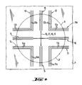
- FIG. 2a and 2b show a configuration of a registration mark PM which is expedient for circular scanning with the device described above, here e.g. for five-color printing (four colors plus black).
- the mark PM comprises four angles 11-14 and a cross 15.
- the angles consist of two legs 11a, 11b-14a, 14b which are inclined at 90 degrees to one another and are arranged in the manner shown at regular intervals in a circle around the center of the cross. Each angle has a different color and accordingly comes from a different print run.
- the individual parts of the registration mark have a defined target position relative to one another (FIG. 2a), but they do not coincide even with ideal printing, that is to say without register errors. This registration mark is therefore not suitable for visual inspection.
- the register mark can also contain four cross-shaped elements 16 - 19 in the center, which ideally overlap.
- Fig. 2a shows the ideal case
- Fig. 2b a registration mark indicating a register error.
- the registration mark shown here can of course be varied in many ways. In particular, it can be expanded to more or less printing inks by adapting the circle division and angle accordingly or be reduced.
- the cross 15 in the middle of the mark can be replaced by four cross-shaped lines or a similar pattern.
- the parts intended for visual inspection can of course also be omitted.
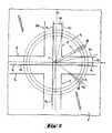
- the rotating scanning head A scans the registration mark PM along a circular path K.
- the diameter of this circular path is approximately 4 mm, for example.
- the center of the circle given by the projection of the axis of rotation Z of the scanning head A is designated Z.
- the zero position (angle reference line) which can be placed as desired (device-fixed) is designated by alpha 0 in FIG. 3.
- the printing direction and the outward direction are indicated by the coordinate axes x and y.
- FIG. 3 shows only a part of the registration mark PM completely drawn in FIGS. 2a and 2b, namely only the black center cross 15 and a color angle 12.
- the distances to the other parts of the brand can be calculated analogously. It can be shown by trivial calculation that the determination of delta x and delta y is independent of the positioning of the device on the printed sheet, both in terms of the distance to the theoretical center of the mark and in relation to the angular position of the device relative to the coordinate network xy. Of course, the device must be roughly positioned so far that the registration mark does not lie outside the (here) circular scanning area of the device.
- the remission signals supplied by the photoelectric converter 7 are processed in the amplifier - A / D converter M.
- the calculation of the distances delta x and delta y and therefrom the register error (by subtracting the defined target distances) takes place in a control and Computing circuit E contained or formed by this evaluation device.
- the control and arithmetic circuit E also controls the drive motors S and 4 and the Light source 1 and controls and coordinates all processes necessary for the measuring process, as is the case with a modern computer-controlled hand densitometer.
- the operation of the device and the display of the measurement results is carried out via the input-output unit D in an analogous manner to manual densitometers.
- the line widths of the registration mark shown in FIGS. 2a and 2b are preferably approximately 0.1 mm, the mark itself has an extension of, for example, approximately 7 ⁇ 7 mm2.
- the distances between two adjacent parallel legs of brand parts belonging to different colors are approximately 0.8 mm. This ensures a practical arrangement with high precision (0.01 mm).
- the scanning of the colored parts of the mark can be done in one or more channels, sequentially or in parallel.
- the color splitting is carried out by color filters arranged in a filter wheel.
- other methods can also be used. It is only essential that the lines of the individual brand parts can be precisely localized and assigned to the corresponding printing inks.
- the registration mark can be designed according to FIG. 4.
- Each of the (here four) colored angles 11 - 14 is provided in triplicate, which makes the measurement redundant and any errors and uncertainties can be eliminated.
- the arrangement of the individual color angles is in turn such that even with the largest register error to be expected, parallel legs are not overprinted.
- the registration marks can also be scanned in two dimensions. This is to be understood to mean that the scanning spot does not move along a single linear path, but rather sweeps over a more or less large area and scans it point by point. This can e.g. 5, by means of a diode row (photodiode array) 30 consisting of a plurality of individual light-sensitive diodes, which rotates about an axis z and thereby scans the registration mark PM along a number of concentric circular tracks k corresponding to the number of photodiodes.
- a diode row (photodiode array) 30 consisting of a plurality of individual light-sensitive diodes, which rotates about an axis z and thereby scans the registration mark PM along a number of concentric circular tracks k corresponding to the number of photodiodes.
- An alternative to this is, for example, rotating only a single photo receiver, but changing the radius of the scanning track.
- the registration marks do not necessarily have to be scanned along a circular track. With a corresponding design of the registration marks and adaptation of the scanning device, linear scanning can also be advantageous. 6 shows an example of this.
- the registration mark PM here consists of conventional registration crosses 41-45.
- the scanning device A generates two scanning lines 51 and 52 arranged at right angles to one another by means of aperture diaphragms suitably arranged in the beam path, the entire device being positioned in operation above the registration mark in such a way that the two scanning lines stand parallel to one leg of the registration cross.
- the scanning head and thus the scanning lines 51 and 52 are now scanned in the diagonal direction d by a stepping motor or other suitable drive. Each scan line only detects the parallel bars of the registration marks. From the sequence of the individual bars can then their relative position and thus the register error can be determined in a simple manner.
- the scanning with the two scanning lines 51 and 52 is carried out separately for both lines. Either two different scanning systems can be provided for this, or means are provided to generate a single scanning line which can be brought into two positions rotated by 90 degrees to one another. Then the scan would e.g. done in succession in two runs.
- the alignment of the scanning head is done with the help of the visor (V).
- Means integrated into the device are also conceivable, with which a visual support of the alignment of the scanning head on the registration mark is given. These are e.g. Magnifying glasses, focusing screens but also optically / electronically controlled small screens.
- the coupling to the measuring beam path is preferably carried out by beam splitters or semitransparent mirrors.
Landscapes
- Engineering & Computer Science (AREA)
- Quality & Reliability (AREA)
- Mechanical Engineering (AREA)
- Spectrometry And Color Measurement (AREA)
- Inking, Control Or Cleaning Of Printing Machines (AREA)
- Length Measuring Devices By Optical Means (AREA)
Priority Applications (1)
| Application Number | Priority Date | Filing Date | Title |
|---|---|---|---|
| AT87104372T ATE63856T1 (de) | 1986-04-18 | 1987-03-25 | Bestimmung des registerfehlers beim mehrfarbendruck. |
Applications Claiming Priority (4)
| Application Number | Priority Date | Filing Date | Title |
|---|---|---|---|
| CH156786 | 1986-04-18 | ||
| CH1567/86 | 1986-04-18 | ||
| CH2392/86 | 1986-06-13 | ||
| CH239286 | 1986-06-13 |
Publications (2)
| Publication Number | Publication Date |
|---|---|
| EP0241773A1 EP0241773A1 (de) | 1987-10-21 |
| EP0241773B1 true EP0241773B1 (de) | 1991-05-29 |
Family
ID=25688020
Family Applications (1)
| Application Number | Title | Priority Date | Filing Date |
|---|---|---|---|
| EP87104372A Expired - Lifetime EP0241773B1 (de) | 1986-04-18 | 1987-03-25 | Bestimmung des Registerfehlers beim Mehrfarbendruck |
Country Status (9)
| Country | Link |
|---|---|
| US (1) | US4856903A (da) |
| EP (1) | EP0241773B1 (da) |
| CN (1) | CN1007332B (da) |
| AU (1) | AU7170187A (da) |
| CA (1) | CA1300921C (da) |
| DE (2) | DE3709858A1 (da) |
| DK (1) | DK186887A (da) |
| ES (1) | ES2023135B3 (da) |
| NO (1) | NO871612L (da) |
Families Citing this family (26)
| Publication number | Priority date | Publication date | Assignee | Title |
|---|---|---|---|---|
| DE3809941A1 (de) * | 1987-03-26 | 1988-10-06 | Koenig & Bauer Ag | Verfahren zum positionieren von plattenzylindern in einer mehrfarben-rotationsdruckmaschine |
| DE3915587C1 (en) * | 1989-05-16 | 1990-11-08 | Man Roland Druckmaschinen Ag, 6050 Offenbach, De | Measurement element for multiple colour offset printing - determines match difference between two partial images independently of quality of image signal |
| DE3933666A1 (de) * | 1989-10-09 | 1991-04-18 | Heidelberger Druckmasch Ag | Vorrichtung und verfahren zur registerverstellung an einer druckmaschine mit mehreren druckwerken |
| DE4012608A1 (de) * | 1990-04-20 | 1991-10-24 | Roland Man Druckmasch | Verfahren und vorrichtung zur bestimmung von passerdifferenzen an druckbildstellen eines mehrfarbenoffsetdruckes |
| US5146099A (en) * | 1990-06-27 | 1992-09-08 | Mitsubishi Denki Kabushiki Kaisha | Apparatus for measuring amount of positional deviation of a recording sheet |
| DE4107080C1 (da) * | 1991-03-06 | 1992-06-04 | Man Miller Druckmaschinen Gmbh, 6222 Geisenheim, De | |
| KR940000910B1 (ko) * | 1991-04-12 | 1994-02-04 | 금성일렉트론 주식회사 | 반도체 칩의 얼라인먼트 방법 및 레이저 리페이어용 타겟이 형성된 반도체 칩 |
| DE4218063C2 (de) * | 1991-05-31 | 1995-07-20 | Sumitomo Heavy Industries | Bildabtastsystem für aufgedruckte Registermarken |
| DE19526373B4 (de) * | 1994-08-08 | 2005-10-20 | Tokyo Kikai Seisakusho Ltd | Vorrichtung zur Registersteuerung bei Rollenrotationsdruckmaschinen und automatisches Verfahren zur Registersteuerung für Rollenrotationsdruckmaschinen zur Korrektur von Registereinstellfehlern |
| DE19517842C2 (de) * | 1995-05-18 | 2000-09-14 | Saechsisches Inst Fuer Die Dru | Vorrichtung zur Messung von Lösungs- und Querpassermarken auf einem Druckprodukt |
| US5796414A (en) * | 1996-03-25 | 1998-08-18 | Hewlett-Packard Company | Systems and method for establishing positional accuracy in two dimensions based on a sensor scan in one dimension |
| US5809894A (en) * | 1997-02-20 | 1998-09-22 | Advanced Vision Technology, Ltd. | System and method for registration control on-press during press set-up and printing |
| US5819655A (en) * | 1997-08-20 | 1998-10-13 | Bristol-Myers Squibb Company | Cyclinder color printing method and product using improved misregistration detection |
| US6478401B1 (en) | 2001-07-06 | 2002-11-12 | Lexmark International, Inc. | Method for determining vertical misalignment between printer print heads |
| DE10250592A1 (de) * | 2002-10-30 | 2004-05-19 | Bst International Gmbh | Verfahren und Vorrichtung zum Erfassen von Druckmarken auf einer bewegten Druckbahn |
| DE102007008017A1 (de) * | 2007-02-15 | 2008-08-21 | Gretag-Macbeth Ag | Farbspaltungskorrekturverfahren |
| DE102007031058A1 (de) | 2007-07-04 | 2009-01-08 | Manroland Ag | Verfahren und Vorrichtung zur Applikation von funktionalen Elementen |
| US7905567B2 (en) * | 2008-05-16 | 2011-03-15 | Avago Technologies Ecbu Ip (Singapore) Pte. Ltd. | Closed-loop printing registration systems, devices, components and methods |
| DE102011009791B4 (de) * | 2011-01-29 | 2016-02-04 | Sächsisches Institut für die Druckindustrie GmbH - Institut des Vereins Polygraph Leipzig e.V. | Messelement zur Vermessung von beliebig übereinanderliegenden Markierungen |
| ITUD20110135A1 (it) * | 2011-08-25 | 2013-02-26 | Applied Materials Italia Srl | Metodo ed impianto di controllo per la stampa di uno schema multistrato |
| CN105091741B (zh) * | 2014-04-23 | 2018-05-08 | 北大方正集团有限公司 | 套印精准度检测方法及装置 |
| CN104647893B (zh) * | 2015-02-09 | 2017-03-15 | 西安科赛图像科技有限责任公司 | 一种基于十字线的印刷套印误差检测方法 |
| CN104792885B (zh) * | 2015-04-03 | 2018-04-10 | 上海和伍精密仪器股份有限公司 | 超声检测中摄像头与超声探头相对位置的标定方法 |
| CN107644183B (zh) * | 2017-09-01 | 2020-10-23 | 福建联迪商用设备有限公司 | 一维码cmos摄像引擎的解码方法及终端 |
| CN108827960A (zh) * | 2018-04-19 | 2018-11-16 | 天津市晟春阳纸制品有限公司 | 一种彩色印刷品套准偏差自动检测装置及检测方法 |
| US11590623B2 (en) | 2018-08-13 | 2023-02-28 | Triton Metal Products Inc. | Machine integrated positioning system |
Family Cites Families (10)
| Publication number | Priority date | Publication date | Assignee | Title |
|---|---|---|---|---|
| DE1233614B (de) * | 1964-07-03 | 1967-02-02 | Leitz Ernst Gmbh | Anordnung zur Bestimmung der Lage von Messmarken nach zwei Koordinaten und Verfahren zur Auswertung der Signale |
| DE2051065A1 (de) * | 1970-10-17 | 1972-04-20 | Siemens Ag | Überwachungseinrichtung auf Registerhaltigkeit von bedruckten Bögen |
| US3989385A (en) * | 1974-09-16 | 1976-11-02 | International Business Machines Corporation | Part locating, mask alignment and mask alignment verification system |
| DD134743A1 (de) * | 1978-02-13 | 1979-03-21 | Arndt Jentzsch | Passmarkenauswertgeraet an mehrfarbendruckmaschinen |
| DE2940233A1 (de) * | 1979-10-04 | 1981-04-16 | Gerhard 8960 Kempten Werner | Passzeichen fuer den mehrfarbendruck |
| DE3136701C1 (de) * | 1981-09-16 | 1983-04-07 | M.A.N.- Roland Druckmaschinen AG, 6050 Offenbach | Vorrichtung zum Abtasten von auf Druckgut aufgedruckten,die Lagegenauigkeit des Druckfarbenauftrages charakterisierender Passmarken |
| JPS5874039A (ja) * | 1981-10-28 | 1983-05-04 | Canon Inc | アライメントマ−クの検出方法 |
| DD224401A1 (de) * | 1984-06-01 | 1985-07-03 | Zeiss Jena Veb Carl | Einrichtung zur bestimmung geometrischer abmessungen an messobjekten |
| EP0177885A3 (en) * | 1984-10-03 | 1988-02-24 | Dai Nippon Insatsu Kabushiki Kaisha | Method and device for registering printing press |
| DE3536263A1 (de) * | 1985-10-11 | 1987-04-16 | Basf Ag | Verfahren zur entfaerbung waessriger glyoxalloesungen |
-
1987
- 1987-03-25 DE DE19873709858 patent/DE3709858A1/de not_active Withdrawn
- 1987-03-25 EP EP87104372A patent/EP0241773B1/de not_active Expired - Lifetime
- 1987-03-25 DE DE8787104372T patent/DE3770316D1/de not_active Expired - Lifetime
- 1987-03-25 ES ES87104372T patent/ES2023135B3/es not_active Expired - Lifetime
- 1987-04-10 DK DK186887A patent/DK186887A/da not_active Application Discontinuation
- 1987-04-15 NO NO871612A patent/NO871612L/no unknown
- 1987-04-16 AU AU71701/87A patent/AU7170187A/en not_active Abandoned
- 1987-04-16 CA CA000534887A patent/CA1300921C/en not_active Expired - Lifetime
- 1987-04-17 US US07/040,570 patent/US4856903A/en not_active Expired - Fee Related
- 1987-04-18 CN CN87103417.4A patent/CN1007332B/zh not_active Expired
Also Published As
| Publication number | Publication date |
|---|---|
| CN87103417A (zh) | 1988-02-17 |
| CA1300921C (en) | 1992-05-19 |
| NO871612L (no) | 1987-10-19 |
| AU7170187A (en) | 1987-10-22 |
| DK186887A (da) | 1987-10-19 |
| DK186887D0 (da) | 1987-04-10 |
| DE3709858A1 (de) | 1987-10-22 |
| NO871612D0 (no) | 1987-04-15 |
| US4856903A (en) | 1989-08-15 |
| ES2023135B3 (es) | 1992-01-01 |
| EP0241773A1 (de) | 1987-10-21 |
| CN1007332B (zh) | 1990-03-28 |
| DE3770316D1 (de) | 1991-07-04 |
Similar Documents
| Publication | Publication Date | Title |
|---|---|---|
| EP0241773B1 (de) | Bestimmung des Registerfehlers beim Mehrfarbendruck | |
| EP0295433B1 (de) | Registermesssystem, wie es im Offsetbereich zur Kontrolle der Lage der Druckplatten Anwendung findet | |
| EP0410253B1 (de) | Vorrichtung zur Durchführung einer umfassenden Qualitätskontrolle an Druckbogen | |
| DE69412281T2 (de) | Ausrichtsysteme | |
| DE3430752C2 (da) | ||
| DE3302798C2 (de) | Vorrichtung zum Voreinstellen an Druckmaschinen | |
| EP0847187B1 (de) | Abtastvorrichtung zur bildelementweisen fotoelektrischen Ausmessung eines Messobjekts | |
| DE2557675A1 (de) | Verfahren zur ausrichtung zweier planarer werkstuecke, z.b. einer maske zu einem wafer oder umgekehrt | |
| CH657318A5 (de) | Vorrichtung zur verkuerzung von einrichtezeiten an druckmaschinen mit registerverstelleinrichtungen. | |
| DE2441421A1 (de) | Verfahren und vorrichtung zur ausrichtung von elektronenstrahlen | |
| DE60007819T2 (de) | Maschine zum Lochen von Platten | |
| DE2516210C2 (de) | Vorrichtung zum Positionieren von Farbauszügen | |
| DE3703998A1 (de) | Einrichtung an druckmaschinen mit stelleinrichtungen fuer umfangs-, seiten- und diagonalregister | |
| DE2121000A1 (de) | Einrichtung zum Vergleich von Mustern | |
| DE102007030571A1 (de) | Farbmessvorrichtung mit zwei unterschiedlich arbeitenden Messeinrichtungen | |
| EP0968637B1 (de) | Verfahren zum vermessen einer einrichtung zur herstellung von elektrischen baugruppen | |
| DE3238167A1 (de) | Verfahren, einrichtung und plattenbiegemaschine zum einrichten einer offset-druckpresse | |
| EP0112403A1 (de) | Opto-elektronische Abtastvorrichtung | |
| EP1843898B1 (de) | Registerverfahren | |
| EP0388697A2 (de) | Verfahren und Vorrichtung zur Festlegung eines Messortes für die Feuchtmittel-Schichtdickenbestimmung einer Offset-Druckplatte | |
| EP0388904B1 (de) | Opto-elektronisches Justierverfahren und Einrichtung zur automatischen rechnergesteuerten Positionierung der Druckschablonen einer Rotationssiebdruckmaschine | |
| DE3249685C2 (da) | ||
| EP0036026B1 (de) | Adressierbare Positioniervorrichtung | |
| DE3014391C2 (de) | Vorrichtung zum Positionieren von Farbauszugsfilmen | |
| DE19517842C2 (de) | Vorrichtung zur Messung von Lösungs- und Querpassermarken auf einem Druckprodukt |
Legal Events
| Date | Code | Title | Description |
|---|---|---|---|
| PUAI | Public reference made under article 153(3) epc to a published international application that has entered the european phase |
Free format text: ORIGINAL CODE: 0009012 |
|
| 17P | Request for examination filed |
Effective date: 19870325 |
|
| AK | Designated contracting states |
Kind code of ref document: A1 Designated state(s): AT BE CH DE ES FR GB IT LI NL SE |
|
| 17Q | First examination report despatched |
Effective date: 19890407 |
|
| GRAA | (expected) grant |
Free format text: ORIGINAL CODE: 0009210 |
|
| AK | Designated contracting states |
Kind code of ref document: B1 Designated state(s): AT BE CH DE ES FR GB IT LI NL SE |
|
| REF | Corresponds to: |
Ref document number: 63856 Country of ref document: AT Date of ref document: 19910615 Kind code of ref document: T |
|
| REF | Corresponds to: |
Ref document number: 3770316 Country of ref document: DE Date of ref document: 19910704 |
|
| ITF | It: translation for a ep patent filed | ||
| ET | Fr: translation filed | ||
| GBT | Gb: translation of ep patent filed (gb section 77(6)(a)/1977) | ||
| REG | Reference to a national code |
Ref country code: ES Ref legal event code: FG2A Ref document number: 2023135 Country of ref document: ES Kind code of ref document: B3 |
|
| PGFP | Annual fee paid to national office [announced via postgrant information from national office to epo] |
Ref country code: AT Payment date: 19920227 Year of fee payment: 6 |
|
| PGFP | Annual fee paid to national office [announced via postgrant information from national office to epo] |
Ref country code: BE Payment date: 19920310 Year of fee payment: 6 |
|
| PGFP | Annual fee paid to national office [announced via postgrant information from national office to epo] |
Ref country code: SE Payment date: 19920316 Year of fee payment: 6 |
|
| PGFP | Annual fee paid to national office [announced via postgrant information from national office to epo] |
Ref country code: ES Payment date: 19920318 Year of fee payment: 6 |
|
| PGFP | Annual fee paid to national office [announced via postgrant information from national office to epo] |
Ref country code: NL Payment date: 19920331 Year of fee payment: 6 |
|
| PLBE | No opposition filed within time limit |
Free format text: ORIGINAL CODE: 0009261 |
|
| STAA | Information on the status of an ep patent application or granted ep patent |
Free format text: STATUS: NO OPPOSITION FILED WITHIN TIME LIMIT |
|
| 26N | No opposition filed | ||
| PGFP | Annual fee paid to national office [announced via postgrant information from national office to epo] |
Ref country code: FR Payment date: 19930305 Year of fee payment: 7 |
|
| PG25 | Lapsed in a contracting state [announced via postgrant information from national office to epo] |
Ref country code: AT Effective date: 19930325 |
|
| PG25 | Lapsed in a contracting state [announced via postgrant information from national office to epo] |
Ref country code: SE Effective date: 19930326 Ref country code: ES Free format text: LAPSE BECAUSE OF NON-PAYMENT OF DUE FEES Effective date: 19930326 |
|
| PG25 | Lapsed in a contracting state [announced via postgrant information from national office to epo] |
Ref country code: BE Effective date: 19930331 |
|
| PGFP | Annual fee paid to national office [announced via postgrant information from national office to epo] |
Ref country code: CH Payment date: 19930526 Year of fee payment: 7 |
|
| BERE | Be: lapsed |
Owner name: HEIDELBERGER DRUCKMASCHINEN A.G. Effective date: 19930331 |
|
| PG25 | Lapsed in a contracting state [announced via postgrant information from national office to epo] |
Ref country code: NL Effective date: 19931001 |
|
| NLV4 | Nl: lapsed or anulled due to non-payment of the annual fee | ||
| PGFP | Annual fee paid to national office [announced via postgrant information from national office to epo] |
Ref country code: GB Payment date: 19940221 Year of fee payment: 8 |
|
| PG25 | Lapsed in a contracting state [announced via postgrant information from national office to epo] |
Ref country code: LI Effective date: 19940331 Ref country code: CH Effective date: 19940331 |
|
| PG25 | Lapsed in a contracting state [announced via postgrant information from national office to epo] |
Ref country code: FR Effective date: 19941130 |
|
| REG | Reference to a national code |
Ref country code: CH Ref legal event code: PL |
|
| REG | Reference to a national code |
Ref country code: FR Ref legal event code: ST |
|
| EUG | Se: european patent has lapsed |
Ref document number: 87104372.5 Effective date: 19931008 |
|
| PG25 | Lapsed in a contracting state [announced via postgrant information from national office to epo] |
Ref country code: GB Effective date: 19950325 |
|
| PGFP | Annual fee paid to national office [announced via postgrant information from national office to epo] |
Ref country code: DE Payment date: 19950412 Year of fee payment: 9 |
|
| GBPC | Gb: european patent ceased through non-payment of renewal fee |
Effective date: 19950325 |
|
| PG25 | Lapsed in a contracting state [announced via postgrant information from national office to epo] |
Ref country code: DE Effective date: 19961203 |
|
| REG | Reference to a national code |
Ref country code: ES Ref legal event code: FD2A Effective date: 19990201 |
|
| PG25 | Lapsed in a contracting state [announced via postgrant information from national office to epo] |
Ref country code: IT Free format text: LAPSE BECAUSE OF NON-PAYMENT OF DUE FEES;WARNING: LAPSES OF ITALIAN PATENTS WITH EFFECTIVE DATE BEFORE 2007 MAY HAVE OCCURRED AT ANY TIME BEFORE 2007. THE CORRECT EFFECTIVE DATE MAY BE DIFFERENT FROM THE ONE RECORDED. Effective date: 20050325 |