EP0241825A2 - Procédé et dispositif pour ajuster une lingotière de coulée continue - Google Patents
Procédé et dispositif pour ajuster une lingotière de coulée continue Download PDFInfo
- Publication number
- EP0241825A2 EP0241825A2 EP87105003A EP87105003A EP0241825A2 EP 0241825 A2 EP0241825 A2 EP 0241825A2 EP 87105003 A EP87105003 A EP 87105003A EP 87105003 A EP87105003 A EP 87105003A EP 0241825 A2 EP0241825 A2 EP 0241825A2
- Authority
- EP
- European Patent Office
- Prior art keywords
- mold
- walls
- wall
- cooled
- continuous casting
- Prior art date
- Legal status (The legal status is an assumption and is not a legal conclusion. Google has not performed a legal analysis and makes no representation as to the accuracy of the status listed.)
- Granted
Links
- 238000009749 continuous casting Methods 0.000 title claims abstract description 24
- 238000000034 method Methods 0.000 title claims description 9
- 230000001154 acute effect Effects 0.000 claims abstract description 11
- 238000006073 displacement reaction Methods 0.000 claims description 34
- 238000005266 casting Methods 0.000 abstract description 23
- 238000001816 cooling Methods 0.000 description 8
- 239000000725 suspension Substances 0.000 description 3
- 229910000831 Steel Inorganic materials 0.000 description 2
- 210000001503 joint Anatomy 0.000 description 2
- 239000010959 steel Substances 0.000 description 2
- 230000000712 assembly Effects 0.000 description 1
- 238000000429 assembly Methods 0.000 description 1
- 230000015572 biosynthetic process Effects 0.000 description 1
- 238000009434 installation Methods 0.000 description 1
- 239000002184 metal Substances 0.000 description 1
Images

Classifications
-
- B—PERFORMING OPERATIONS; TRANSPORTING
- B22—CASTING; POWDER METALLURGY
- B22D—CASTING OF METALS; CASTING OF OTHER SUBSTANCES BY THE SAME PROCESSES OR DEVICES
- B22D11/00—Continuous casting of metals, i.e. casting in indefinite lengths
- B22D11/04—Continuous casting of metals, i.e. casting in indefinite lengths into open-ended moulds
- B22D11/05—Continuous casting of metals, i.e. casting in indefinite lengths into open-ended moulds into moulds having adjustable walls
Definitions
- the invention relates to a method and a device for adjusting a continuous casting mold with the features of the preamble of claim 1 and of claim 5.
- the continuous casting plant can be adapted to different strand cross-sections by changing the mold or by changing the size of the mold within the continuous casting plant.
- slab molds can be remotely controlled both during casting breaks or during the continuous casting operation in the strand width.
- a continuous casting mold with a rectangular cross section which is connected to a frame or a base plate.
- Four mold walls with their cooled wall surfaces form a mold cavity.
- a cooled mold wall surface collide with an end face of an adjacent mold wall.
- the four molded walls are clamped together using lock screws.
- Between each mold wall and the frame are further set screws that allow adjustment of the mold cavity.
- the mold walls can be moved transversely to the direction of the strand to change the casting cone or their mutual distance. Adjusting such molds is time-consuming and is usually carried out in the mold workshop.
- the adjustment range is further narrowly limited and a new adjustment requires gauges and measuring instruments.
- the invention has for its object to provide a mold, the mold cavity is two-dimensional, i.e. in width and in thickness, is adjustable. Furthermore, the adjustment within the continuous casting plant and, if necessary, should also be able to be carried out during continuous casting operation. With larger format adjustments, it should also be possible to change the casting cone of the mold cavity.
- the method according to the invention or the mold according to the invention make it possible to adjust a mold two-dimensionally within the continuous casting installation by remote control in one adjustment cycle. If desired, the adjustment can also be carried out while the casting operation is running. Alignment to a subsequent strand guide is ensured by a fixed side that remains in place during the adjustment. If desired, it can be rigidly connected to the frame.
- a first mold wall can be displaced along an axis of movement which is at an acute angle to its mold wall surface.
- a second and a third mold wall can be moved along axes of movement which run transversely or parallel to their mold wall surfaces.
- all four mold walls can be moved simultaneously along components of motion which form an acute angle with their cooled mold wall surfaces.
- a continuous casting mold provided for this method contains the features of claim 6.
- the frame be arranged to be movable relative to a machine frame by means of a displacement device transversely to the direction of the strand.
- a displacement device is procedurally to be controlled in such a way that when the fixed side of the mold is shifted by a predetermined displacement path, the frame is simultaneously displaced in the opposite direction by the same displacement path.
- An advantageous two-dimensional alignment with subsequent support guide elements can be achieved if, according to an additional feature, another mold wall as a fixed element side is formed, which is moved during the mold cavity adjustment only in the plane of its cooled wall surface.
- a course of movement of the mold wall which is oblique to the cooled mold wall surface can be achieved by various means.
- the displacement device for the mold wall has a threaded spindle which forms an acute angle to the mold wall surface of the moving wall.
- the inclined movement of the mold wall is less than or greater than 45 degrees. If square and rectangular cross sections are to be adjusted, it can be particularly advantageous if the displacement device for the mold wall has two movement spindles which are arranged at right angles to one another and which can be displaced in a predetermined ratio of the movement speed via a computer control.
- Gap formation in the mold corners during the adjustment but also during the casting operation can lead to casting problems or to casting breaks.
- the mold walls are each resiliently supported on a supporting wall so that each mold wall has a parallel to the mold wall surface and slight displacement transverse to the direction of the strand is made possible.
- the spring force should be selected so that the face of the mold wall automatically presses against the mold wall surface of the adjacent wall with sufficient contact pressure.
- the displacement device of each mold wall can be arranged in the frame so as to be pivotable about an axis provided parallel to the associated mold wall surface the. So that an automatic adjustment of the casting cone is made possible during the casting operation, a remotely controlled pivoting device can be provided between the frame and the displacement device.
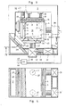
- a continuous casting mold with a square mold cavity 13 is shown. It consists of a base plate or a frame 2 and four mold walls 3 - 6 attached to it, which form the mold cavity 13 with their cooled wall surfaces 8 - 11. At the four corners of the mold cavity 13 there is a cooled mold wall surface, e.g. 8, together with an end face 16 of the adjacent mold wall 4.
- Several force devices are arranged to adjust the cross section of the mold cavity 13.
- the mold wall 3 can be referred to as a fixed side. It can be fixed to the frame 2 with spindles 12, or it can be rigidly or adjustably connected to the frame 2 by other means. The mold wall 3 moves not during the format adjustment or only for the purpose of adapting the cone of the from cavity to the new format.
- the mold wall 6 can also be referred to as a fixed side because it only moves in the direction of the arrow 14, i.e. moved in the plane of its cooled wall surface 11. It thus remains in alignment with the support members, not shown, which follow the mold. For this movement, two displacement devices 28 arranged one above the other, for example in the form of threaded spindles, are provided. With 15 a suspension and guide device for the mold wall 6 is shown.
- the mold wall 4 can be moved transversely to the strand running direction 22 during a format adjustment in the direction of a double arrow 21 to change the mutual distance from the mold wall 6.
- displacement devices 27 are provided, for example as threaded spindles with a corresponding spindle drive.
- the mold wall 5 is displaced along a movement component, represented by arrow 18, by means of a displacement device 25, which comprises a driven threaded spindle 26.
- the displacement device 25 can form the support element for the mold wall 5 and is provided between the latter and the frame 2.
- the movement component forms an acute angle 20 to the cooled mold wall surface 10. In the present example, this angle 20 is 45 degrees for an adjustment of a square mold cavity cross section. Dashed lines show the mold walls 4, 5 and 6 in a new position for a smaller casting format.
- FIG. 2 schematically shows a support guide following the mold in the form of a cooling plate 17.
- This cooling plate 17 is connected to the movable mold wall 4 via a carrier 19. When the mold wall 4 is moved, the cooling plate 17 also moves.
- the cooling plate 17 is supported on the carrier 19 via springs 23. The cooling plate 17 thus presses against a strand with a predetermined spring force. Unevenness on the strand, in particular during an adjustment movement during a running casting, can thus be compensated for without loss of contact between the strand and the cooling plate 17.
- the mold wall 5 likewise moves along a movement component which is represented by the arrow 18.
- a displacement device 35 is moved in the arrow direction 42 by the displacement device 36 and a spindle 38, which in turn is connected to the mold wall 5 via a spindle 37.
- the movement component represented by arrow 18 is thus a resultant movement of the two spindles 37 and 38, which are arranged at right angles to one another and which can be moved by a computer control 44 known per se with a predetermined ratio of the movement speed.
- the resilient contact pressure or the spring travel can also compensate for conicity adjustments on the mold wall 4, which are made possible by movement devices 39, in such a way that no gap gap can arise between the mold walls 4 and 5.
- the mold walls require a correspondingly low pivotability in the frame 2.
- arrow 40 indicates a pivoting movement of the mold wall 5, for example about a central axis 41, of the upper spindle 37.
- the mold wall 3 is elastically suspended or supported with respect to the frame 2 by means of bolts 30 and springs 31.
- Spring assemblies 33 are also arranged between the mold wall 6 and displacement devices 32.
- the displacement devices 32, 35, 36, 39 are connected to a computer control 44 which controls the displacements of the walls 4, 5, 6 according to program entries 45, 46.
- a computer control 44 which controls the displacements of the walls 4, 5, 6 according to program entries 45, 46.
- hydraulic relief cylinders can reduce these spring forces to a desired level during the adjustment movement.
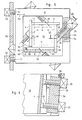
- FIGS. 5 and 6 the reference numerals for the same components are the same as in FIG. 1.
- all mold walls in this mold are equipped with similar displacement devices, preferably movement spindles 26. If the format is changed during the casting operation, all four mold walls 3 - 6 can be moved simultaneously along components of movement according to arrows 18. The movement components form an acute angle 20 to the associated mold wall surfaces 8-11, which is 45 degrees when square formats are adjusted.
- the mold wall 6 forms the fixed side, which is advantageously not moved relative to a fixed side of the strand guide or a machine axis.
- a machine frame part is shown, on which the frame 2 of the mold is attached via a displacement device in the form of two spindles 51.
- the frame 2 of the mold can be moved transversely to the direction of the strand running (arrow 53) by means of spindle drives 52 relative to the machine frame part 50. If the mold wall 6, like all other mold walls 3, 4, 5, is displaced by a predetermined displacement path, the frame 2 can simultaneously be displaced in the opposite direction by the same displacement path via the spindles 51.
- the mold wall 6 thus remains in relation to the machine axis, although it moves relative to the frame 2.
- FIGS. 5 and 6 On the left side of FIGS. 5 and 6, a pivoting device for the spindles 26, the sliding devices 25 and the mold wall 4 is shown.
- a spindle guide 55 or a spindle suspension is pivotably arranged in the frame 2 via an axis 56. Via this axis 56, e.g. during a displacement movement of the mold wall 4, its inclination or the conicity of the mold cavity 13 can be changed by means of a drivable pivoting device 58.
- the mold wall 5 is arranged on a support wall 60, sliding parallel to the mold wall surface 10.
- a spring 62 is tensioned between the end face 61 opposite the butt 59 and an angle part 63 of the supporting wall 60. It generates a predetermined contact pressure on the butt joint 59.
- a guide 65 is provided, which can follow the pivoting movements in the conicity adjustment of the mold wall 4 about the axis 56.
- an elastic buffer can be provided, for example, between the spindles 26 and the associated mold walls 3 - 6 to accommodate small pivoting movements.
Landscapes
- Engineering & Computer Science (AREA)
- Mechanical Engineering (AREA)
- Continuous Casting (AREA)
- Molds, Cores, And Manufacturing Methods Thereof (AREA)
- Magnetic Resonance Imaging Apparatus (AREA)
- Moulds For Moulding Plastics Or The Like (AREA)
- Dental Prosthetics (AREA)
- Casting Devices For Molds (AREA)
- Confectionery (AREA)
Priority Applications (1)
| Application Number | Priority Date | Filing Date | Title |
|---|---|---|---|
| AT87105003T ATE50176T1 (de) | 1986-04-15 | 1987-04-04 | Verfahren und vorrichtung zum verstellen einer stranggiesskokille. |
Applications Claiming Priority (2)
| Application Number | Priority Date | Filing Date | Title |
|---|---|---|---|
| CH1494/86A CH670779A5 (fr) | 1986-04-15 | 1986-04-15 | |
| CH1494/86 | 1986-04-15 |
Publications (3)
| Publication Number | Publication Date |
|---|---|
| EP0241825A2 true EP0241825A2 (fr) | 1987-10-21 |
| EP0241825A3 EP0241825A3 (en) | 1988-07-20 |
| EP0241825B1 EP0241825B1 (fr) | 1990-02-07 |
Family
ID=4211767
Family Applications (1)
| Application Number | Title | Priority Date | Filing Date |
|---|---|---|---|
| EP87105003A Expired - Lifetime EP0241825B1 (fr) | 1986-04-15 | 1987-04-04 | Procédé et dispositif pour ajuster une lingotière de coulée continue |
Country Status (8)
| Country | Link |
|---|---|
| US (1) | US4719966A (fr) |
| EP (1) | EP0241825B1 (fr) |
| JP (1) | JPS6316835A (fr) |
| AT (1) | ATE50176T1 (fr) |
| CA (1) | CA1304563C (fr) |
| CH (1) | CH670779A5 (fr) |
| DE (1) | DE3761613D1 (fr) |
| ES (1) | ES2015280B3 (fr) |
Cited By (2)
| Publication number | Priority date | Publication date | Assignee | Title |
|---|---|---|---|---|
| US6041848A (en) * | 1998-01-13 | 2000-03-28 | Sms Concast Division Of Sms-Schloemann Siemag Inc. | Adjustable continuous casting mold |
| EP0920937A3 (fr) * | 1997-12-05 | 2000-05-03 | Sms Schloemann-Siemag Aktiengesellschaft | Lingotière pour la coulée continue |
Families Citing this family (8)
| Publication number | Priority date | Publication date | Assignee | Title |
|---|---|---|---|---|
| US6056040A (en) * | 1997-10-10 | 2000-05-02 | Alcan International Limited | Mould device with adjustable walls |
| DE19842110C1 (de) * | 1998-09-08 | 1999-08-26 | Mannesmann Ag | Verstellbare Plattenkokille |
| US6857464B2 (en) * | 2002-09-19 | 2005-02-22 | Hatch Associates Ltd. | Adjustable casting mold |
| KR101503444B1 (ko) * | 2012-12-12 | 2015-03-17 | 주식회사 포스코 | 주형 및 이를 이용한 연속 주조 방법 |
| ITUD20130054A1 (it) * | 2013-04-23 | 2014-10-24 | Danieli Off Mecc | Apparato per la colata continua e metodo di montaggio di detto apparato per la colata continua |
| JP6323244B2 (ja) * | 2014-08-08 | 2018-05-16 | トヨタ自動車株式会社 | 高温成形用金型 |
| CN115697585A (zh) * | 2020-07-22 | 2023-02-03 | 诺维尔里斯公司 | 直接激冷铸造模具系统 |
| CN117862418A (zh) * | 2023-12-12 | 2024-04-12 | 中国第一汽车股份有限公司 | 用于制造铝硅合金的铸造模具及铝硅合金的制造方法 |
Family Cites Families (3)
| Publication number | Priority date | Publication date | Assignee | Title |
|---|---|---|---|---|
| US3049769A (en) * | 1961-07-14 | 1962-08-21 | United States Steel Corp | Adjustable-taper mold for continuous casting |
| DE1758982C3 (de) * | 1968-09-11 | 1973-09-20 | Demag Ag, 4100 Duisburg | Langsgeteilte Stranggießkokille für Metalle, insbesondere fur Stahl |
| SU531374A1 (ru) * | 1975-03-24 | 1982-05-30 | Московский Трижды Ордена Ленина И Ордена Трудового Красного Знамени Автомобильный Завод Им.Лихачева | Кристаллизатор |
-
1986
- 1986-04-15 CH CH1494/86A patent/CH670779A5/de not_active IP Right Cessation
-
1987
- 1987-04-04 DE DE8787105003T patent/DE3761613D1/de not_active Expired - Lifetime
- 1987-04-04 AT AT87105003T patent/ATE50176T1/de active
- 1987-04-04 EP EP87105003A patent/EP0241825B1/fr not_active Expired - Lifetime
- 1987-04-04 ES ES87105003T patent/ES2015280B3/es not_active Expired - Lifetime
- 1987-04-07 CA CA000534072A patent/CA1304563C/fr not_active Expired - Lifetime
- 1987-04-10 US US07/037,220 patent/US4719966A/en not_active Expired - Fee Related
- 1987-04-14 JP JP62089994A patent/JPS6316835A/ja active Pending
Cited By (3)
| Publication number | Priority date | Publication date | Assignee | Title |
|---|---|---|---|---|
| EP0920937A3 (fr) * | 1997-12-05 | 2000-05-03 | Sms Schloemann-Siemag Aktiengesellschaft | Lingotière pour la coulée continue |
| US6145580A (en) * | 1997-12-05 | 2000-11-14 | Sms Schloemann-Siemag Ag | Continuous-casting mold with small side adjustment |
| US6041848A (en) * | 1998-01-13 | 2000-03-28 | Sms Concast Division Of Sms-Schloemann Siemag Inc. | Adjustable continuous casting mold |
Also Published As
| Publication number | Publication date |
|---|---|
| DE3761613D1 (de) | 1990-03-15 |
| CH670779A5 (fr) | 1989-07-14 |
| CA1304563C (fr) | 1992-07-07 |
| ATE50176T1 (de) | 1990-02-15 |
| EP0241825B1 (fr) | 1990-02-07 |
| ES2015280B3 (es) | 1990-08-16 |
| EP0241825A3 (en) | 1988-07-20 |
| JPS6316835A (ja) | 1988-01-23 |
| US4719966A (en) | 1988-01-19 |
Similar Documents
| Publication | Publication Date | Title |
|---|---|---|
| DE19913710B4 (de) | Antriebsvorrichtung für ein Gleitstück einer Kniehebelpresse | |
| EP0212433B1 (fr) | Dispositif de réglage pour déplacer les cylindres de laminoir selon l'axe de laminage | |
| DE69009446T2 (de) | Werkzeug für biegepresse zum freibiegen. | |
| EP0722820A1 (fr) | Dispositif de fermeture de moule sans colonnes | |
| EP0241825B1 (fr) | Procédé et dispositif pour ajuster une lingotière de coulée continue | |
| EP0463201A1 (fr) | Installation de coulée continue d'acier contenant un dispositif pour éliminer des bourrelets produits pendant le découpage à l'oxygène | |
| DE69832426T2 (de) | Pressvorrichtung für Metallblech | |
| DE3501716C2 (de) | Verfahren und Einrichtung zum Verstellen der Schmalseitenplatten einer Stranggießkokille beim Stranggießen von Metallen, insbesondere von Stahl | |
| DE69604874T2 (de) | Stützvorrichtung für die Seitenwände einer Walzenstranggiessanlage zum Herstellen metallischer Bänder | |
| EP0086405A1 (fr) | Procédé et dispositif pour refroidir et supporter une barre dans une lingotière à plaques d'une installation de coulée continue d'acier | |
| DE4444941C2 (de) | Stranggießkokille | |
| DE69614191T2 (de) | Walzenkreuzvorrichtung für Walzwerk | |
| EP0104373B1 (fr) | Dispositif de compensation du retrait pour une coquille de coulée continue | |
| DE3604963C2 (de) | Einsatz zum Unterteilen einer Stranggießkokille | |
| DE69604903T2 (de) | Stranggiessform | |
| EP0595765A1 (fr) | Presse plieuse | |
| EP1021261B1 (fr) | Procede et dispositif de fabrication de brames de differents formats | |
| EP0198230B1 (fr) | Machine d'électro-érosion | |
| DE60211080T2 (de) | Verstellbare Formmatrize, insbesondere für Abkantpressen | |
| DE3338542T1 (de) | Hydraulische Presse | |
| DE69513263T2 (de) | Vorrichtung zum Stranggiessen von Produkten mit einem Rundprofilabschnitt und Produkten mit einem Profilabschnitt mit ebener Fläche | |
| DE1427895A1 (de) | Vorrichtung zum Einstellen des Walzenspaltes bei Walzwerken | |
| DE60001114T2 (de) | Vorrichtung zur herstellung von giessformteilen mit führungshilfsmitteln | |
| EP0128342B1 (fr) | Presse avec un dispositif pour l'éjection des pièces et un dispositif pour l'ajustage de l'altitude de fermeture | |
| DE1758072A1 (de) | Stranggiesskokille |
Legal Events
| Date | Code | Title | Description |
|---|---|---|---|
| PUAI | Public reference made under article 153(3) epc to a published international application that has entered the european phase |
Free format text: ORIGINAL CODE: 0009012 |
|
| AK | Designated contracting states |
Kind code of ref document: A2 Designated state(s): AT DE ES FR GB IT |
|
| PUAL | Search report despatched |
Free format text: ORIGINAL CODE: 0009013 |
|
| AK | Designated contracting states |
Kind code of ref document: A3 Designated state(s): AT DE ES FR GB IT |
|
| 17P | Request for examination filed |
Effective date: 19881209 |
|
| 17Q | First examination report despatched |
Effective date: 19890620 |
|
| GRAA | (expected) grant |
Free format text: ORIGINAL CODE: 0009210 |
|
| AK | Designated contracting states |
Kind code of ref document: B1 Designated state(s): AT DE ES FR GB IT |
|
| ITF | It: translation for a ep patent filed | ||
| REF | Corresponds to: |
Ref document number: 50176 Country of ref document: AT Date of ref document: 19900215 Kind code of ref document: T |
|
| GBT | Gb: translation of ep patent filed (gb section 77(6)(a)/1977) | ||
| REF | Corresponds to: |
Ref document number: 3761613 Country of ref document: DE Date of ref document: 19900315 |
|
| ET | Fr: translation filed | ||
| PLBE | No opposition filed within time limit |
Free format text: ORIGINAL CODE: 0009261 |
|
| STAA | Information on the status of an ep patent application or granted ep patent |
Free format text: STATUS: NO OPPOSITION FILED WITHIN TIME LIMIT |
|
| 26N | No opposition filed | ||
| ITTA | It: last paid annual fee | ||
| PGFP | Annual fee paid to national office [announced via postgrant information from national office to epo] |
Ref country code: FR Payment date: 19930310 Year of fee payment: 7 |
|
| PGFP | Annual fee paid to national office [announced via postgrant information from national office to epo] |
Ref country code: AT Payment date: 19930311 Year of fee payment: 7 |
|
| PGFP | Annual fee paid to national office [announced via postgrant information from national office to epo] |
Ref country code: GB Payment date: 19930316 Year of fee payment: 7 |
|
| PGFP | Annual fee paid to national office [announced via postgrant information from national office to epo] |
Ref country code: DE Payment date: 19930322 Year of fee payment: 7 |
|
| PGFP | Annual fee paid to national office [announced via postgrant information from national office to epo] |
Ref country code: ES Payment date: 19930326 Year of fee payment: 7 |
|
| PG25 | Lapsed in a contracting state [announced via postgrant information from national office to epo] |
Ref country code: GB Effective date: 19940404 Ref country code: AT Effective date: 19940404 |
|
| PG25 | Lapsed in a contracting state [announced via postgrant information from national office to epo] |
Ref country code: ES Free format text: LAPSE BECAUSE OF NON-PAYMENT OF DUE FEES Effective date: 19940405 |
|
| GBPC | Gb: european patent ceased through non-payment of renewal fee |
Effective date: 19940404 |
|
| PG25 | Lapsed in a contracting state [announced via postgrant information from national office to epo] |
Ref country code: FR Effective date: 19941229 |
|
| PG25 | Lapsed in a contracting state [announced via postgrant information from national office to epo] |
Ref country code: DE Effective date: 19950103 |
|
| REG | Reference to a national code |
Ref country code: FR Ref legal event code: ST |
|
| REG | Reference to a national code |
Ref country code: ES Ref legal event code: FD2A Effective date: 19990301 |
|
| PG25 | Lapsed in a contracting state [announced via postgrant information from national office to epo] |
Ref country code: IT Free format text: LAPSE BECAUSE OF NON-PAYMENT OF DUE FEES;WARNING: LAPSES OF ITALIAN PATENTS WITH EFFECTIVE DATE BEFORE 2007 MAY HAVE OCCURRED AT ANY TIME BEFORE 2007. THE CORRECT EFFECTIVE DATE MAY BE DIFFERENT FROM THE ONE RECORDED. Effective date: 20050404 |