EP0241862A2 - Dispositif d'échange de fluide entre un premier et au moins un second réservoir - Google Patents
Dispositif d'échange de fluide entre un premier et au moins un second réservoir Download PDFInfo
- Publication number
- EP0241862A2 EP0241862A2 EP87105256A EP87105256A EP0241862A2 EP 0241862 A2 EP0241862 A2 EP 0241862A2 EP 87105256 A EP87105256 A EP 87105256A EP 87105256 A EP87105256 A EP 87105256A EP 0241862 A2 EP0241862 A2 EP 0241862A2
- Authority
- EP
- European Patent Office
- Prior art keywords
- line
- container
- containers
- liquid
- compensating
- Prior art date
- Legal status (The legal status is an assumption and is not a legal conclusion. Google has not performed a legal analysis and makes no representation as to the accuracy of the status listed.)
- Granted
Links
Images
Classifications
-
- B—PERFORMING OPERATIONS; TRANSPORTING
- B60—VEHICLES IN GENERAL
- B60K—ARRANGEMENT OR MOUNTING OF PROPULSION UNITS OR OF TRANSMISSIONS IN VEHICLES; ARRANGEMENT OR MOUNTING OF PLURAL DIVERSE PRIME-MOVERS IN VEHICLES; AUXILIARY DRIVES FOR VEHICLES; INSTRUMENTATION OR DASHBOARDS FOR VEHICLES; ARRANGEMENTS IN CONNECTION WITH COOLING, AIR INTAKE, GAS EXHAUST OR FUEL SUPPLY OF PROPULSION UNITS IN VEHICLES
- B60K15/00—Arrangement in connection with fuel supply of combustion engines or other fuel consuming energy converters, e.g. fuel cells; Mounting or construction of fuel tanks
- B60K15/03—Fuel tanks
- B60K15/077—Fuel tanks with means modifying or controlling distribution or motion of fuel, e.g. to prevent noise, surge, splash or fuel starvation
-
- B—PERFORMING OPERATIONS; TRANSPORTING
- B60—VEHICLES IN GENERAL
- B60K—ARRANGEMENT OR MOUNTING OF PROPULSION UNITS OR OF TRANSMISSIONS IN VEHICLES; ARRANGEMENT OR MOUNTING OF PLURAL DIVERSE PRIME-MOVERS IN VEHICLES; AUXILIARY DRIVES FOR VEHICLES; INSTRUMENTATION OR DASHBOARDS FOR VEHICLES; ARRANGEMENTS IN CONNECTION WITH COOLING, AIR INTAKE, GAS EXHAUST OR FUEL SUPPLY OF PROPULSION UNITS IN VEHICLES
- B60K15/00—Arrangement in connection with fuel supply of combustion engines or other fuel consuming energy converters, e.g. fuel cells; Mounting or construction of fuel tanks
- B60K15/03—Fuel tanks
- B60K2015/03118—Multiple tanks, i.e. two or more separate tanks
-
- B—PERFORMING OPERATIONS; TRANSPORTING
- B60—VEHICLES IN GENERAL
- B60K—ARRANGEMENT OR MOUNTING OF PROPULSION UNITS OR OF TRANSMISSIONS IN VEHICLES; ARRANGEMENT OR MOUNTING OF PLURAL DIVERSE PRIME-MOVERS IN VEHICLES; AUXILIARY DRIVES FOR VEHICLES; INSTRUMENTATION OR DASHBOARDS FOR VEHICLES; ARRANGEMENTS IN CONNECTION WITH COOLING, AIR INTAKE, GAS EXHAUST OR FUEL SUPPLY OF PROPULSION UNITS IN VEHICLES
- B60K15/00—Arrangement in connection with fuel supply of combustion engines or other fuel consuming energy converters, e.g. fuel cells; Mounting or construction of fuel tanks
- B60K15/03—Fuel tanks
- B60K2015/03118—Multiple tanks, i.e. two or more separate tanks
- B60K2015/03138—Pumping means between the compartments
-
- B—PERFORMING OPERATIONS; TRANSPORTING
- B60—VEHICLES IN GENERAL
- B60K—ARRANGEMENT OR MOUNTING OF PROPULSION UNITS OR OF TRANSMISSIONS IN VEHICLES; ARRANGEMENT OR MOUNTING OF PLURAL DIVERSE PRIME-MOVERS IN VEHICLES; AUXILIARY DRIVES FOR VEHICLES; INSTRUMENTATION OR DASHBOARDS FOR VEHICLES; ARRANGEMENTS IN CONNECTION WITH COOLING, AIR INTAKE, GAS EXHAUST OR FUEL SUPPLY OF PROPULSION UNITS IN VEHICLES
- B60K15/00—Arrangement in connection with fuel supply of combustion engines or other fuel consuming energy converters, e.g. fuel cells; Mounting or construction of fuel tanks
- B60K15/03—Fuel tanks
- B60K2015/03118—Multiple tanks, i.e. two or more separate tanks
- B60K2015/03144—Fluid connections between the tanks
-
- B—PERFORMING OPERATIONS; TRANSPORTING
- B60—VEHICLES IN GENERAL
- B60K—ARRANGEMENT OR MOUNTING OF PROPULSION UNITS OR OF TRANSMISSIONS IN VEHICLES; ARRANGEMENT OR MOUNTING OF PLURAL DIVERSE PRIME-MOVERS IN VEHICLES; AUXILIARY DRIVES FOR VEHICLES; INSTRUMENTATION OR DASHBOARDS FOR VEHICLES; ARRANGEMENTS IN CONNECTION WITH COOLING, AIR INTAKE, GAS EXHAUST OR FUEL SUPPLY OF PROPULSION UNITS IN VEHICLES
- B60K15/00—Arrangement in connection with fuel supply of combustion engines or other fuel consuming energy converters, e.g. fuel cells; Mounting or construction of fuel tanks
- B60K15/03—Fuel tanks
- B60K2015/03164—Modular concepts for fuel tanks
-
- F—MECHANICAL ENGINEERING; LIGHTING; HEATING; WEAPONS; BLASTING
- F02—COMBUSTION ENGINES; HOT-GAS OR COMBUSTION-PRODUCT ENGINE PLANTS
- F02M—SUPPLYING COMBUSTION ENGINES IN GENERAL WITH COMBUSTIBLE MIXTURES OR CONSTITUENTS THEREOF
- F02M37/00—Apparatus or systems for feeding liquid fuel from storage containers to carburettors or fuel-injection apparatus; Arrangements for purifying liquid fuel specially adapted for, or arranged on, internal-combustion engines
- F02M37/0047—Layout or arrangement of systems for feeding fuel
- F02M37/007—Layout or arrangement of systems for feeding fuel characterised by its use in vehicles, in stationary plants or in small engines, e.g. hand held tools
-
- F—MECHANICAL ENGINEERING; LIGHTING; HEATING; WEAPONS; BLASTING
- F02—COMBUSTION ENGINES; HOT-GAS OR COMBUSTION-PRODUCT ENGINE PLANTS
- F02M—SUPPLYING COMBUSTION ENGINES IN GENERAL WITH COMBUSTIBLE MIXTURES OR CONSTITUENTS THEREOF
- F02M37/00—Apparatus or systems for feeding liquid fuel from storage containers to carburettors or fuel-injection apparatus; Arrangements for purifying liquid fuel specially adapted for, or arranged on, internal-combustion engines
- F02M37/0076—Details of the fuel feeding system related to the fuel tank
- F02M37/0088—Multiple separate fuel tanks or tanks being at least partially partitioned
-
- Y—GENERAL TAGGING OF NEW TECHNOLOGICAL DEVELOPMENTS; GENERAL TAGGING OF CROSS-SECTIONAL TECHNOLOGIES SPANNING OVER SEVERAL SECTIONS OF THE IPC; TECHNICAL SUBJECTS COVERED BY FORMER USPC CROSS-REFERENCE ART COLLECTIONS [XRACs] AND DIGESTS
- Y10—TECHNICAL SUBJECTS COVERED BY FORMER USPC
- Y10T—TECHNICAL SUBJECTS COVERED BY FORMER US CLASSIFICATION
- Y10T137/00—Fluid handling
- Y10T137/0753—Control by change of position or inertia of system
- Y10T137/0898—By shifting of liquid level
-
- Y—GENERAL TAGGING OF NEW TECHNOLOGICAL DEVELOPMENTS; GENERAL TAGGING OF CROSS-SECTIONAL TECHNOLOGIES SPANNING OVER SEVERAL SECTIONS OF THE IPC; TECHNICAL SUBJECTS COVERED BY FORMER USPC CROSS-REFERENCE ART COLLECTIONS [XRACs] AND DIGESTS
- Y10—TECHNICAL SUBJECTS COVERED BY FORMER USPC
- Y10T—TECHNICAL SUBJECTS COVERED BY FORMER US CLASSIFICATION
- Y10T137/00—Fluid handling
- Y10T137/8593—Systems
- Y10T137/86187—Plural tanks or compartments connected for serial flow
-
- Y—GENERAL TAGGING OF NEW TECHNOLOGICAL DEVELOPMENTS; GENERAL TAGGING OF CROSS-SECTIONAL TECHNOLOGIES SPANNING OVER SEVERAL SECTIONS OF THE IPC; TECHNICAL SUBJECTS COVERED BY FORMER USPC CROSS-REFERENCE ART COLLECTIONS [XRACs] AND DIGESTS
- Y10—TECHNICAL SUBJECTS COVERED BY FORMER USPC
- Y10T—TECHNICAL SUBJECTS COVERED BY FORMER US CLASSIFICATION
- Y10T137/00—Fluid handling
- Y10T137/8593—Systems
- Y10T137/86292—System with plural openings, one a gas vent or access opening
- Y10T137/86324—Tank with gas vent and inlet or outlet
Definitions
- the invention relates to a device for exchanging liquid between a first and at least a second container, in particular between two interconnected tanks of a motor vehicle, with a line opening in the bottom region of both containers and with an outlet line leading into the first container.
- This one-line fluid exchange device functions satisfactorily as long as both saddle tanks are approximately at the same level, i.e. H. when the line runs horizontally.
- there is no longer any liquid exchange as soon as the second saddle tank, which is not connected to the outlet pipe, is lower than the first saddle tank due to the inclination of the tractor. Rather, the first saddle tank will empty into the second, and the fuel supply will be interrupted.
- the object on which the invention is based is seen in creating a device for exchanging liquid between a first and at least a second container, with the aid of which a filling of the container connected to the outlet line which is sufficient under normal conditions is achieved in a cost-effective manner.
- the liquid barrier can be designed as a completely conventional check valve; however, it can also operate in a float-controlled manner in order to prevent the first container from being overfilled and thus prevents an imbalance from being generated.
- Such an imbalance can, however, also be prevented by the presence of a compensating line, as described in claims 2 to 5.
- a compensating line as described in claims 2 to 5.
- the content of the first container can be a maximum of a quarter of the content of the second container if the equalizing line ends in the middle of both containers.
- the large dimensioning of the passage cross section allows a quick compensation as long as the liquid level is above the mouths of the compensation line. The same occurs if the second container is above the first due to the inclination of the motor vehicle or a frame supporting the containers.
- the arrangement of the mouths at different heights in the two containers according to claim 5 leads to a rapid exchange of liquid via the compensating line and not only through the line even with a slight lifting of the second container compared to the first container.
- the arrangement of the beginning of the output line according to claim 6 has the effect that approximately the same residual amount always remains with completely emptied containers, regardless of which side the containers are inclined.
- the ratio of the sizes of the passage cross section of the outlet line and the line ensures that liquid is always fed to the first container faster than its outlet through the outlet line.
- Both containers manage with only one ventilation device that is normally required if a ventilation line connecting both containers is provided.
- the application of the device according to the invention is in no way in the field of agricultural tractors or industrial machinery seem limited; rather, planes, tankers, ships or buildings can also be provided with this device if they contain two or even more interconnected containers, the relative position of which changes in the vertical direction.
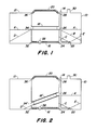
- FIG. 1 shows a right or first container 10, a left or second container 12, an outlet line 14, a compensating line 18, a line 16 and a ventilation line 20.
- Such an assembly is typically found on an agricultural tractor, not shown, the containers then normally taking on the function of fuel tanks, one of which is attached to each side of the agricultural tractor as seen in the longitudinal direction thereof. Information such as above, below, left and right are understood with a view to the drawing.
- the outlet line 14 leads from the upper end region of the first container 10 down to its bottom surface and begins there approximately in the middle, ie its inlet opening 22 lies approximately at the intersection of the diagonals of the bottom surface.
- the upper end of the output line 14 is connected to a fuel feed pump, not shown.
- an opening 24 is provided which connects the first container 10 to the line 16.
- the first container 10 is provided with an opening 26 on which the compensating line 28 engages.
- Another mouth 28 is located in the upper end region of the first container 10, which is used for ventilation or is connected to the ventilation line 20.
- the top of the first container contains a filler neck 30 through which liquid, that is to say fuel in the special case, is filled into the two containers 10 and 12 and which contains an opening to the atmosphere.
- the left second container 12 is essentially of the same size and construction as the first right container 10, and it has the same height as this when the containers are on a horizontal plane.
- the left-hand second container 12 also contains openings 32, 34 and 36 for the line 16, the compensating line 34 and the ventilation line 20, that is to say in their lower, their middle and their upper end region.
- the line 16 connects the orifices 24 and 32 to one another and contains a liquid barrier 38 in the manner of a check valve, which acts against little or no opening pressure and only allows liquid flow from the second container 12 into the first.
- the equalizing line 18 connects the two orifices 26 and 34 to one another and has a much larger diameter than the line 16. This large diameter of the equalizing line 18 enables a rapid exchange of liquid between the two containers when the liquid level in the one container 10, 12 is above that of the other, provided that this is still above the equalization line 18.
- the total passage cross section of the compensating line 18 is preferably larger than that of the line 16.
- the orifices 28 and 36 are connected to one another via the ventilation line 20, which provides a rapid exchange of air between the two containers 10, 12, so that the liquid can flow freely from one container to the other 10, 12.
- the same purpose is achieved if, instead of the ventilation line 20, a ventilation or ventilation opening is provided in each container 10, 12.
- the device according to the invention is thus essentially composed of the line 16 and the liquid barrier 38.
- the liquid flows continuously through the compensating line 18 from one container 10, 12 to another 12, 10 and vice versa.
- the two containers 10, 12 are still quite full, there is also sufficient liquid or fuel that can be sucked out of the first container 10, and the entire system works like known systems with a conventional device that only has a single line in the Has bottom area of both containers 10, 12. If, however, the liquid volume has reduced to the mark -A-, then the line 16 and the liquid barrier 38 function such that they retain a minimal minimum amount of the liquid or the fuel in the first container 10.
- the liquid retained in the first container 10 can then be sucked off through the outlet line 14, namely until the inlet opening 22 exits above the liquid level marked with -C-.
- the volume between the lines -B- and -C- will not be used up before the containers 10, 12 or the agricultural tractor return to the horizontal or the opposite inclination.
- any liquid flows above the line -A- of the left second container 12 via the compensating line 18 and the line 16 into the right first container 10.
- the liquid flows Liquid only through line 16 to maintain the liquid level in the left second container 12 at the same level as in the right first container 10. If the left second container 12 is brought upwards until the line -D- lies horizontally, then the liquid moves above the line -D- via the compensating line 18 and the line 16 into the right container 10. When the liquid no longer flows through the compensating line 18 can flow out, then it continues its outflow into the first container 10 through the line 16.
- the right first container 10 is fed and discharged fuel until one of the minimum levels -E- or -C- is reached when the containers 10, 12 or the tractor between a horizontal and a non-horizontal or between two are not oscillate in horizontal positions.
- the size of the volume flow between the second container 12 and the first container 10 when a liquid level is established below the mouth 26 of the compensating line 18 is determined by the flow cross section of the line 16, which should be such that at least compared to the outlet line 14 double the amount of liquid can flow through.
- the compensating line 18 preferably extends into the openings 26, 34 approximately at the middle of the height of the containers 10, 12. This feature allows the right first container 10 to retain sufficient fluid when tilted upward while simultaneously limiting the difference in fluid volumes between the two containers 10, 12 to minimize an imbalance between the two amounts of fluid.
- the compensating line 18 can also be arranged in a slightly modified form, as shown in FIG. 2, ie the mouth 34 ⁇ of the compensating line 18 ⁇ comes to lie in the left-hand container 12 just above the mouth 32. This measure quickly transports liquid from the left container 12 into the right container 10 when the left one is raised. As a result of the arrangement of the equalizing line 18 configureden in the indicated inclined manner and the displacement of the mouth 34 ⁇ downward, liquid will still flow through the equalizing line 18 ⁇ until the liquid level drops below the line -D ⁇ -.
- the compensating line 18 ⁇ in the position or inclination shown ensures that liquid is quickly refilled into the right-hand first container 10.
- the device according to the invention can, however, also be used in a single container with a plurality of chambers, of which the chamber provided with the outlet line 14, for. B. may be located in the middle between the other chambers.
Landscapes
- Engineering & Computer Science (AREA)
- Life Sciences & Earth Sciences (AREA)
- Sustainable Development (AREA)
- Sustainable Energy (AREA)
- Chemical & Material Sciences (AREA)
- Combustion & Propulsion (AREA)
- Transportation (AREA)
- Mechanical Engineering (AREA)
- Cooling, Air Intake And Gas Exhaust, And Fuel Tank Arrangements In Propulsion Units (AREA)
Applications Claiming Priority (2)
| Application Number | Priority Date | Filing Date | Title |
|---|---|---|---|
| US06/851,998 US4664144A (en) | 1986-04-14 | 1986-04-14 | Fuel recovery system for dual tanks |
| US851998 | 1986-04-14 |
Publications (3)
| Publication Number | Publication Date |
|---|---|
| EP0241862A2 true EP0241862A2 (fr) | 1987-10-21 |
| EP0241862A3 EP0241862A3 (en) | 1989-03-22 |
| EP0241862B1 EP0241862B1 (fr) | 1991-03-27 |
Family
ID=25312245
Family Applications (1)
| Application Number | Title | Priority Date | Filing Date |
|---|---|---|---|
| EP19870105256 Expired - Lifetime EP0241862B1 (fr) | 1986-04-14 | 1987-04-09 | Dispositif d'échange de fluide entre un premier et au moins un second réservoir |
Country Status (5)
| Country | Link |
|---|---|
| US (1) | US4664144A (fr) |
| EP (1) | EP0241862B1 (fr) |
| AU (1) | AU577219B2 (fr) |
| CA (1) | CA1279275C (fr) |
| DE (1) | DE3768844D1 (fr) |
Cited By (3)
| Publication number | Priority date | Publication date | Assignee | Title |
|---|---|---|---|---|
| FR2676027A1 (fr) * | 1991-04-30 | 1992-11-06 | Peugeot | Reservoir de liquide, notamment reservoir de carburant de vehicule automobile. |
| DE4227121A1 (de) * | 1992-08-17 | 1994-02-24 | Kloeckner Humboldt Deutz Ag | Tankanlage |
| US7073525B2 (en) | 2003-09-22 | 2006-07-11 | Kia Motors Corporation | Multi-tank connecting device for liquefied petroleum injection vehicle |
Families Citing this family (19)
| Publication number | Priority date | Publication date | Assignee | Title |
|---|---|---|---|---|
| DE3719834C2 (de) * | 1986-09-18 | 1988-07-07 | Daimler Benz Ag | Entlueftungseinrichtung fuer kraftstofftanks von kraftfahrzeugen |
| US4930537A (en) * | 1989-06-02 | 1990-06-05 | Paccar Inc. | Vehicle multiple-tank fuel system |
| US6196805B1 (en) * | 1999-11-09 | 2001-03-06 | Peter V. Reilley | Method and apparatus for oscillatingly elevating fluid |
| US6782916B2 (en) * | 2001-12-20 | 2004-08-31 | Case Corporation | Flapper valve system |
| JP2004284559A (ja) * | 2003-03-25 | 2004-10-14 | Kobelco Contstruction Machinery Ltd | 作業機械の給油構造 |
| US6789568B1 (en) * | 2003-06-17 | 2004-09-14 | Case, Llc | Fluid flow control mechansim |
| TR200501431A2 (tr) * | 2005-04-20 | 2006-11-21 | Uzel Maki̇na San. A.Ş. | Çift depolu yan yana konumlandırılmış yakıt depo sistemleri |
| FR2901190B1 (fr) * | 2006-05-16 | 2009-01-23 | Inergy Automotive Systems Res | Reservoir liquide et procede pour le fabriquer |
| GB0725176D0 (en) * | 2007-12-22 | 2008-01-30 | Agco Sa | Implement attachment |
| US20110114636A1 (en) * | 2009-11-16 | 2011-05-19 | Glenn Erckert | Two-sided automobile fuel filling system |
| DE102013106962A1 (de) * | 2013-07-03 | 2015-01-22 | CLAAS Tractor S.A.S | Landwirtschaftliches Fahrzeug |
| JP6435912B2 (ja) * | 2015-02-23 | 2018-12-12 | 株式会社デンソー | 燃料タンクシステム |
| WO2017023220A2 (fr) * | 2015-07-31 | 2017-02-09 | Hema Endustri Anonim Sirketi | Perfectionnement apporté à un système d'aspiration de carburant |
| IL265133B (en) * | 2018-03-04 | 2020-11-30 | Navon Edo | System and method for sealing wires, cables, pipes and drain holes through buffer |
| JP6708685B2 (ja) | 2018-03-23 | 2020-06-10 | 日立建機株式会社 | 作業車両のタンク |
| JP6752248B2 (ja) * | 2018-03-23 | 2020-09-09 | 日立建機株式会社 | 作業車両 |
| DE102018208639B4 (de) * | 2018-05-30 | 2020-08-13 | Magna powertrain gmbh & co kg | Kupplungssystem |
| RU2752919C2 (ru) * | 2019-12-02 | 2021-08-11 | Общество с ограниченной ответственностью "Комбайновый завод "Ростсельмаш" | Бак топливный сельхозмашины |
| GB2638958A (en) * | 2024-02-28 | 2025-09-10 | Caterpillar Inc | Slewing work machine with primary and secondary fuel tanks and detachable counterweight mount |
Family Cites Families (15)
| Publication number | Priority date | Publication date | Assignee | Title |
|---|---|---|---|---|
| US1751456A (en) * | 1927-12-08 | 1930-03-18 | Mid West Specialty Company | Liquid-reserve tank |
| US2276963A (en) * | 1940-02-13 | 1942-03-17 | James F Griffin | Fuel tank |
| US2332007A (en) * | 1941-03-14 | 1943-10-19 | Arthur L Parker | Sump selector valve for fuel tanks |
| BE622872A (fr) * | 1961-10-28 | |||
| US3311183A (en) * | 1963-05-13 | 1967-03-28 | Massey Ferguson Inc | Tractor having saddle gas tanks |
| US3610220A (en) * | 1969-05-29 | 1971-10-05 | Toyota Motor Co Ltd | Fuel tank construction |
| DE1933960A1 (de) * | 1969-07-04 | 1971-01-21 | Daimler Benz Ag | Sicherheitsvorrichtung an einem Kraftwagentank |
| DE2440905A1 (de) * | 1974-08-27 | 1976-03-11 | Porsche Ag | Kraftstoffbehaelteranlage fuer kraftfahrzeuge |
| DE2442152A1 (de) * | 1974-09-03 | 1976-03-11 | Porsche Ag | Kraftstoffbehaelteranlage fuer kraftfahrzeuge |
| DE2739292A1 (de) * | 1977-08-31 | 1979-03-15 | Agfa Gevaert Ag | Einrichtung zum vermischen von fluessigkeiten |
| NL7903657A (nl) * | 1979-05-10 | 1980-11-12 | Lely Nv C Van Der | Tank voor het transporteren van vloeibaar materiaal. |
| US4288086A (en) * | 1980-01-22 | 1981-09-08 | International Harvester Company | Fuel tank arrangement for a tractor |
| DE3224943C2 (de) * | 1982-07-03 | 1984-06-28 | Daimler-Benz Ag, 7000 Stuttgart | Kraftstoffbehälteranlage für Kraftfahrzeuge, insbesondere Omnibusse |
| JPS604424A (ja) * | 1983-06-22 | 1985-01-10 | Honda Motor Co Ltd | 車両における燃料タンクのエアベント装置 |
| AU547914B2 (en) * | 1983-10-18 | 1985-11-14 | Schiemann. W. | Fuel tank |
-
1986
- 1986-04-14 US US06/851,998 patent/US4664144A/en not_active Expired - Lifetime
-
1987
- 1987-03-27 CA CA 533122 patent/CA1279275C/fr not_active Expired - Lifetime
- 1987-04-09 DE DE8787105256T patent/DE3768844D1/de not_active Expired - Lifetime
- 1987-04-09 EP EP19870105256 patent/EP0241862B1/fr not_active Expired - Lifetime
- 1987-04-14 AU AU71780/87A patent/AU577219B2/en not_active Ceased
Cited By (4)
| Publication number | Priority date | Publication date | Assignee | Title |
|---|---|---|---|---|
| FR2676027A1 (fr) * | 1991-04-30 | 1992-11-06 | Peugeot | Reservoir de liquide, notamment reservoir de carburant de vehicule automobile. |
| DE4227121A1 (de) * | 1992-08-17 | 1994-02-24 | Kloeckner Humboldt Deutz Ag | Tankanlage |
| US7073525B2 (en) | 2003-09-22 | 2006-07-11 | Kia Motors Corporation | Multi-tank connecting device for liquefied petroleum injection vehicle |
| DE10360936B4 (de) * | 2003-09-22 | 2007-02-15 | Kia Motors Corporation | Mehrfachtank-Verbindungsvorrichtung für ein Fahrzeug mit Flüssiggas-Einspritzung |
Also Published As
| Publication number | Publication date |
|---|---|
| EP0241862B1 (fr) | 1991-03-27 |
| AU7178087A (en) | 1987-10-15 |
| CA1279275C (fr) | 1991-01-22 |
| EP0241862A3 (en) | 1989-03-22 |
| DE3768844D1 (de) | 1991-05-02 |
| US4664144A (en) | 1987-05-12 |
| AU577219B2 (en) | 1988-09-15 |
Similar Documents
| Publication | Publication Date | Title |
|---|---|---|
| EP0241862B1 (fr) | Dispositif d'échange de fluide entre un premier et au moins un second réservoir | |
| EP0598078B1 (fr) | Reservoir a carburant comportant un recipient | |
| DE2701658C2 (de) | Automatische Umschaltvorrichtung für Anlagen zur Abgabe von zähflüssigen Flüssigkeiten | |
| EP1332065A1 (fr) | Reservoir de carburant | |
| DE102009004370B4 (de) | Kraftstofftankstruktur | |
| DE102006015730A1 (de) | Kraftstoffzuführsystem für einen Verbrennungsmotor | |
| DE4425694A1 (de) | Kontinuierliches Tintennachfüllsystem für Tintenstrahlpatronen sowie Tintenstrahlpatronen und Tintenvorratsbehälter für ein solches System | |
| DE3213554A1 (de) | Fluessigkeits-zuteilungsvorrichtung | |
| EP0036197A1 (fr) | Réservoir de fluide hydraulique pour véhicule | |
| DE60120608T2 (de) | Behälteranordnung und Behälter | |
| DE4116350C2 (fr) | ||
| EP0570739A1 (fr) | Système de drainage | |
| DE2327830C2 (de) | Brennstoffversorgungseinrichtung einer Heizvorrichtung für ein Kraftfahrzeug | |
| DE4301761C2 (de) | Tanksystem für flüssigen Kraftstoff, insbesondere für Verbrennungsmotoren in Kraftfahrzeugen | |
| DE3134940A1 (de) | Dosierpumpe | |
| DE2239484B2 (de) | Druckgesteuerte Dosiervorrichtung für Flüssigkeiten | |
| DE69618345T2 (de) | Methode und Anlage zum Umfüllen erschmolzenen Metalls | |
| DE102014202361B4 (de) | Kraftstofftanksystem | |
| DE1653723B2 (de) | Selbstansaugende Kreiselpumpe | |
| DE1922360A1 (de) | OElpumpe | |
| DE4118902C2 (de) | Kraftstoffbehälteranordnung für Nutzfahrzeuge | |
| DE2909144C2 (de) | Dosiervorrichtung zur Abgabe eines Vergaserkraftstoff-Öl-Gemisches | |
| DE102005041813B4 (de) | Vorrichtung zum Verringern der Fließgeschwindigkeit einer Hydraulikflüssigkeit für ein hydraulisches System | |
| DE2427320A1 (de) | Anlage zum abscheiden von luft aus fluessigkeiten | |
| DE3312819A1 (de) | Kraftstoffbehaelter fuer kraftfahrzeuge |
Legal Events
| Date | Code | Title | Description |
|---|---|---|---|
| PUAI | Public reference made under article 153(3) epc to a published international application that has entered the european phase |
Free format text: ORIGINAL CODE: 0009012 |
|
| AK | Designated contracting states |
Kind code of ref document: A2 Designated state(s): DE FR GB IT |
|
| 17P | Request for examination filed |
Effective date: 19880312 |
|
| PUAL | Search report despatched |
Free format text: ORIGINAL CODE: 0009013 |
|
| AK | Designated contracting states |
Kind code of ref document: A3 Designated state(s): DE FR GB IT |
|
| RHK1 | Main classification (correction) |
Ipc: B60K 15/02 |
|
| 17Q | First examination report despatched |
Effective date: 19900109 |
|
| ITF | It: translation for a ep patent filed | ||
| GRAA | (expected) grant |
Free format text: ORIGINAL CODE: 0009210 |
|
| AK | Designated contracting states |
Kind code of ref document: B1 Designated state(s): DE FR GB IT |
|
| GBT | Gb: translation of ep patent filed (gb section 77(6)(a)/1977) | ||
| REF | Corresponds to: |
Ref document number: 3768844 Country of ref document: DE Date of ref document: 19910502 |
|
| ET | Fr: translation filed | ||
| PLBE | No opposition filed within time limit |
Free format text: ORIGINAL CODE: 0009261 |
|
| STAA | Information on the status of an ep patent application or granted ep patent |
Free format text: STATUS: NO OPPOSITION FILED WITHIN TIME LIMIT |
|
| 26N | No opposition filed | ||
| PGFP | Annual fee paid to national office [announced via postgrant information from national office to epo] |
Ref country code: GB Payment date: 20010322 Year of fee payment: 15 |
|
| PGFP | Annual fee paid to national office [announced via postgrant information from national office to epo] |
Ref country code: FR Payment date: 20010405 Year of fee payment: 15 |
|
| REG | Reference to a national code |
Ref country code: GB Ref legal event code: IF02 |
|
| PG25 | Lapsed in a contracting state [announced via postgrant information from national office to epo] |
Ref country code: GB Free format text: LAPSE BECAUSE OF NON-PAYMENT OF DUE FEES Effective date: 20020409 |
|
| GBPC | Gb: european patent ceased through non-payment of renewal fee |
Effective date: 20020409 |
|
| PG25 | Lapsed in a contracting state [announced via postgrant information from national office to epo] |
Ref country code: FR Free format text: LAPSE BECAUSE OF NON-PAYMENT OF DUE FEES Effective date: 20021231 |
|
| REG | Reference to a national code |
Ref country code: FR Ref legal event code: ST |
|
| PGFP | Annual fee paid to national office [announced via postgrant information from national office to epo] |
Ref country code: DE Payment date: 20030430 Year of fee payment: 17 |
|
| PG25 | Lapsed in a contracting state [announced via postgrant information from national office to epo] |
Ref country code: DE Free format text: LAPSE BECAUSE OF NON-PAYMENT OF DUE FEES Effective date: 20041103 |
|
| PG25 | Lapsed in a contracting state [announced via postgrant information from national office to epo] |
Ref country code: IT Free format text: LAPSE BECAUSE OF NON-PAYMENT OF DUE FEES;WARNING: LAPSES OF ITALIAN PATENTS WITH EFFECTIVE DATE BEFORE 2007 MAY HAVE OCCURRED AT ANY TIME BEFORE 2007. THE CORRECT EFFECTIVE DATE MAY BE DIFFERENT FROM THE ONE RECORDED. Effective date: 20050409 |