EP0241921A1 - Antenne à haute efficacite - Google Patents
Antenne à haute efficacite Download PDFInfo
- Publication number
- EP0241921A1 EP0241921A1 EP87105544A EP87105544A EP0241921A1 EP 0241921 A1 EP0241921 A1 EP 0241921A1 EP 87105544 A EP87105544 A EP 87105544A EP 87105544 A EP87105544 A EP 87105544A EP 0241921 A1 EP0241921 A1 EP 0241921A1
- Authority
- EP
- European Patent Office
- Prior art keywords
- reflector
- radiating
- coaxial cables
- antenna
- wire
- Prior art date
- Legal status (The legal status is an assumption and is not a legal conclusion. Google has not performed a legal analysis and makes no representation as to the accuracy of the status listed.)
- Granted
Links
- 239000002184 metal Substances 0.000 claims description 13
- 230000005855 radiation Effects 0.000 claims description 9
- 239000004020 conductor Substances 0.000 claims description 5
- 239000000470 constituent Substances 0.000 description 1
- 230000008878 coupling Effects 0.000 description 1
- 238000010168 coupling process Methods 0.000 description 1
- 238000005859 coupling reaction Methods 0.000 description 1
- 238000009413 insulation Methods 0.000 description 1
- 239000000543 intermediate Substances 0.000 description 1
- 238000005457 optimization Methods 0.000 description 1
Images

Classifications
-
- H—ELECTRICITY
- H01—ELECTRIC ELEMENTS
- H01Q—ANTENNAS, i.e. RADIO AERIALS
- H01Q19/00—Combinations of primary active antenna elements and units with secondary devices, e.g. with quasi-optical devices, for giving the antenna a desired directional characteristic
- H01Q19/10—Combinations of primary active antenna elements and units with secondary devices, e.g. with quasi-optical devices, for giving the antenna a desired directional characteristic using reflecting surfaces
- H01Q19/18—Combinations of primary active antenna elements and units with secondary devices, e.g. with quasi-optical devices, for giving the antenna a desired directional characteristic using reflecting surfaces having two or more spaced reflecting surfaces
- H01Q19/185—Combinations of primary active antenna elements and units with secondary devices, e.g. with quasi-optical devices, for giving the antenna a desired directional characteristic using reflecting surfaces having two or more spaced reflecting surfaces wherein the surfaces are plane
-
- H—ELECTRICITY
- H01—ELECTRIC ELEMENTS
- H01Q—ANTENNAS, i.e. RADIO AERIALS
- H01Q11/00—Electrically-long antennas having dimensions more than twice the shortest operating wavelength and consisting of conductive active radiating elements
- H01Q11/02—Non-resonant antennas, e.g. travelling-wave antenna
- H01Q11/08—Helical antennas
Definitions
- the present invention relates to a high efficiency antenna.
- the source commonly known as “Short Backfire” is known. It consists of a dipole or two dipoles (crossed if there are two) and a cylindrical reflector.
- the performances of this type of antenna have been studied by HW EHRENSPECK and are described in the article "A New Class of Medium - Size, High-efficiency Reflector Antennas” (IEEE Transactions on Antennas and Propagation "of March 1974). document describes a type of reflector antenna allowing a greater directional gain than those obtained with conventional reflector antennas of the same area.
- An antenna of this type comprises a cylindrical reflector and a feed system located in the center of this Such an antenna is analyzed as the combination of two radiating sources whose maximum radiation and mutual phase relationships can be adjusted simply to obtain greater directional gain in a direction perpendicular to the bottom surface of the reflector. directional gain is explained on the basis of a virtual extension of the radiation opening beyond the physical dimensions of the reflector.
- dmin the minimum value of the reflector diameter, dmin, for a "Short Backfire" type antenna, dmin must be compatible with the size of the dipole: dmin> 0.75 ⁇ .
- the subject of the invention is a structure making it possible to take advantage of the advantageous phenomenon which appears for d ⁇ 0.75 ⁇ , while having a reflector diameter d 0.7 ⁇ .
- the invention provides a high-efficiency antenna comprising a reflector consisting of a bottom and walls of direction perpendicular to this bottom and of cylindrical shape, inside which is disposed a device radiating in the direction perpendicular to it.
- the radiating device comprising at least one wire wound helically on either side of the axis of symmetry of the reflector which is the axis of radiation of said device, each wire being short-circuited at the reflector by its end located on the side of the bottom of this reflector and being fed by its other end, characterized in that at least one coaxial cable situated inside the helix formed by the radiating wire (s) makes it possible to supply this (or these) radiating wire (s).
- the advantages of the present invention compared to “Short Backfire” type antennas are as follows: - The diameter of the reflector is not limited by the size of the dipole, - The directivity of the radiating element is modular, unlike a "Short Backfire" antenna whose directivity of the dipole is constant.
- the subject of the invention is an antenna in which four coaxial cables are arranged inside a quadrifilar helix, the central cores of the first two coaxial cables, which are power cables, being connected by first circuits metallic to the central cores of the other two coaxial cables, a metal plate disposed at a certain distance from this end making it possible to connect the central cores of these last two coaxial cables and the outer conductors of the four coaxial cables so that the impedance present in output of the two power cables, i.e. 50 ⁇ , the external parts relative to the reflector of these four coaxial cables being connected to the four wires by the inter mediate of four second metal circuits.
- the invention relates to an antenna in which the first metal circuits are produced by metal layers arranged on either side of a first printed circuit, the second metal circuits being produced by metal layers arranged on a first face. a second print superimposed by its second face with one of the faces of the first printed circuit.
- FIG. 1 illustrates a schematic perspective view of an antenna according to the invention, the reflector being shown in section
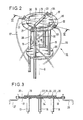
- - Figure 2 illustrates a partial perspective view of the radiating source of the invention
- FIG. 3 illustrates a sectional view along plane III-III of the radiating source shown in FIG. 2.
- the present invention relates to a radiating element, consisting of a quadrifilar helix 10, placed in a reflector 11 having a bottom 8 and side walls 9 of direction perpendicular to this bottom and of cylindrical shape.
- the dimensions of the reflector 11 are optimized to obtain the superposition in phase, in the direction of the radiation axis ⁇ , of the components radiated by the propeller 10 on the one hand, and by the upper edge 12 of the reflector 11 on the other go.
- the antenna according to the invention comprises four coaxial cables 13, 14, 15, 16 which are in directions parallel to the axis of the radiation ⁇ .
- the central cores 20 and 21 of the first two coaxial cables 13, 14, which are power cables, are connected by circuits 24 and 25 to the central cores 22 and 23 of the coaxial cables 15 and 16. These central cores 22 and 23 are short-circuited to the outer conductors of the coaxial cables 13, 14, 15, 16 by a metal plate 26 at a distance e such that the impedance presented at the output of the coaxial cables 13 and 14 is 50 ⁇ .
- the quadrifilar propeller 10 consists of four radiating strands 27, 28, 29, 30 which are fed from the top; their base being short-circuited to the reflector 11, which allows it to be assimilated, at first analysis, to a curved dipole.
- radiating strands 27, 28, 29 and 30 are connected to the external conductors of the coaxials 13, 14, 15, 16 by the circuits 31, 32, 33, 34. These radiating strands are short-circuited at the reflector 11 via 'a plate 17. Depending on the value of the diameter d of the reflector, the height h of the reflector is optimized.
- the circuits 24, 25 which make it possible to connect the central cores 20 and 21 of the cables 13 and 14 to the cores 22 and 23 of the cables 15 and 16, are represented by metallic deposits made on either side another of a first printed circuit 35;
- the circuits 31, 32, 33 and 34 which allow the external conductors of the coaxial cables 13, 14, 15 and 16 to be connected to the radiating strands 27, 28, 29, and 30 are metallic deposits made on a first face of a second printed circuit 36, the second face of which is superimposed on one of the faces of the first printed circuit 35.
- Such an antenna is mainly used at frequencies below 4 GHz.
- the antennas of the known art comprising a dipole located inside a cylindrical reflector whose directivity is given, in the antenna according to the invention it is possible to act, at a given frequency, on the diameter / height of the reflector.
- the criterion of coherence of the radiation coming from the propeller 10 on the one hand, and from the upper edge 12 of the reflector 11 on the other hand correlates the reduction in diameter d, to an increase in the height h of the reflector 11, and therefore improves the direct insulation between elements.
- the optimization criterion is to obtain maximum directivity in the axis of the radiation. But this criterion could be to obtain a maximum ellipticity rate on a blanket given, for example with a multidirectional antenna.
- the radiating element 10 can also be a helix composed of one or more wires: monofilar, bifilar, etc. This helix can also be of conical shape.
Landscapes
- Aerials With Secondary Devices (AREA)
- Variable-Direction Aerials And Aerial Arrays (AREA)
Abstract
Description
- La présente invention est relative à une antenne à haute efficacité.
- En matière d'éléments rayonnants à haute efficacité, on connaît la source communément appelée "Short Backfire". Elle est constituée d'un dipole ou de deux dipoles (croisés s'il y en a deux) et d'un réflecteur cylindrique. Les performances de ce type d'antenne ont été étudiées par H.W. EHRENSPECK et sont décrites dans l'article "A New Class of Medium - Size, High-efficiency Reflector Antennas" (IEEE Transactions on Antennas and Propagation" de mars 1974). Ce document décrit un type d'antenne à réflecteur permettant un plus grand gain directif que ceux obtenus avec des antennes à réflecteur conventionnelles de même surface. Une antenne de ce type comprend un réflecteur de forme cylindrique et un système d'alimentation situé au centre de ce réflecteur. Une telle antenne est analysée comme la combinaison de deux sources rayonnantes dont le rayonnement maximum et les relations de phase mutuelles peuvent être ajustés simplement pour obtenir un plus grand gain directif dans une direction perpendiculaire à la surface du fond du réflecteur. L'accroissement de gain directif est expliqué sur la base d'une extension virtuelle de l'ouverture de rayonnement au delà des dimentions physiques du réflecteur.
- L'auteur compare l'efficacité de ce type de source, au rendement théorique maximal d'une ouverture rayonnante de même dimension. Ce rendement est défini par rapport à Dmax (directivité maximale d'une ouverture rayonnante)
Dmax =
avec A : aire de la surface considérée
et λ : longueur d'onde. - Pour certaines caractéristiques du réflecteur (Diamètre d = 2.45 λ , hauteur h = 0.57 λ ), la directivité mesurée est supérieure à la directivité maximale de l'ouverture rayonnante équivalente. Ce phénomène, selon les travaux précités, se reproduit pour des valeurs de diamètre : d < 0.75 λ .
- Si on considère la valeur minimale du diamètre du réflecteur, dmin, pour une antenne du type "Short Backfire", dmin doit être compatible avec l'encombrement du dipole : dmin > 0.75 λ .
- Il y a donc incompatibilité entre les deux relations relatives au diamètre du réflecteur.
- L'invention a pour objet une structure permettant de profiter du phénomène avantageux qui apparait pour d < 0,75 λ , tout en ayant un diamètre de réflecteur d0,7 λ .

- L'invention propose à cet effet une antenne à haute efficacité comprenant un réflecteur constitué d'un fond et de parois de direction perpendiculaire à ce fond et de forme cylindrique, à l'intérieur duquel est disposé un dispositif rayonnant dans la direction perpendiculaire à ce fond, le dispositif rayonnant comprenant au moins un fil enroulé en hélice de part et d'autre de l'axe de symétrie du réflecteur qui est l'axe de rayonnement dudit dispositif, chaque fil étant court-circuité au réflecteur par son extrémité située du côté du fond de ce réflecteur et étant alimenté par son autre extrémité caractérisé en ce que au moins un câble coaxial situé à l'intérieur de l'hélice formée par le (ou les) fil (s) rayonnant permet d'alimenter ce (ou ces) fil (s) rayonnants.
- Les avantages que possèdent la présente invention par rapport aux antennes du type "Short Backfire" sont les suivants :
- Le diamètre du réflecteur n'est pas limité par l'encombrement du dipole,
- La directivité de l'élément rayonnant est modulable, contrairement à une antenne "Short Backfire" dont la directivité du dipole est constante. - Plus précisément l'invention a pour objet une antenne dans laquelle quatre câbles coaxiaux sont disposés à l'intérieur d'une hélice quadrifilaire, les âmes centrales des deux premiers câbles coaxiaux, qui sont des câbles d'alimentation, étant reliées par des premiers circuits métalliques aux âmes centrales des deux autres câbles coaxiaux, une plaque métallique disposée à une certaine distance de cette extrémité permettant de relier les âmes centrales de ces deux derniers câbles coaxiaux et les conducteurs extérieurs des quatre câbles coaxiaux de telle manière que l'impédance présente en sortie des deux câbles d'alimentation soit 50Ω, les parties extérieures par rapport au réflecteur de ces quatre câbles coaxiaux étant reliées aux quatre fils par l'inter médiare de quatre seconds circuits métalliques.
- Avantageusement l'invention se rapporte à une antenne dans laquelle les premiers circuits métalliques sont réalisés par des couches métalliques disposées de part et d'autre d'un premier circuit imprimé, les seconds circuits métalliques étant réalisés par des couches métalliques disposées sur une première face d'un second imprimé superposé par sa seconde face avec l'une des faces du premier circuit imprimé.
- Les caractéristiques et avantages de l'invention ressortiront d'ailleurs de la description qui va suivre, à titre d'exemple non limitatif, en référence aux dessins annexés sur lesquels :
- la figure 1 illustre une vue en perspective schématique d'une antenne selon l'invention, le réflecteur étant représenté en coupe ;
- la figure 2 illustre une vue partielle en perspective de la source rayonnante de l'invention ;
- la figure 3 illustre une vue en coupe selon le plan III-III de la source rayonnante représentée à la figure 2. - La présente invention se rapporte à une élément rayonnant, constitué d'une hélice quadrifilaire 10, placé dans un réflecteur 11 ayant un fond 8 et des parois 9 latérales de direction perpendiculaire à ce fond et de forme cylindrique. Les dimensions du réflecteur 11 sont optimisées pour obtenir la superposition en phase, dans la direction de l'axe de rayonnement Δ , des composantes rayonnées par l'hélice 10 d'une part, et par le bord supérieur 12 du réflecteur 11 d'autre part.
- L'antenne selon l'invention comprend quatre câbles coaxiaux 13, 14, 15, 16 qui sont de directions parallèles à l'axe du rayonnement Δ .
- Les âmes centrales 20 et 21 des deux premiers câbles coaxiaux 13, 14, qui sont des câbles d'alimentation, sont reliées par des circuits 24 et 25 aux âmes centrales 22 et 23 des câbles coaxiaux 15 et 16. Ces âmes centrales 22 et 23 sont court-circuitées aux conducteurs extérieurs des câbles coaxiaux 13, 14, 15, 16 par une plaque métallique 26 à une distance e telle que l'impédance présentée en sortie des câbles coaxiaux 13 et 14 soit de 50 Ω .
- L'hélice quadrifilaire 10 est constituée de quatre brins rayonnants 27, 28, 29, 30 qui sont alimentés par le sommet ; leur base étant court-circuitée au réflecteur 11, ce qui lui permet d'être assimilée, en première analyse, à un dipole recourbé.
- Ces brins rayonnants 27, 28, 29 et 30 sont reliés aux conducteurs extérieurs des coaxiaux 13, 14, 15, 16 par les circuits 31, 32, 33, 34. Ces brins rayonnants sont court-circuités au réflecteur 11 par l'intermédiaire d'une plaque 17. En fonction de la valeur du diamètre d du réflecteur, la hauteur h du réflecteur est optimisée.
- Sur les figures 1, 2 et 3 les circuits 24, 25 qui permettent de relier les âmes centrales 20 et 21 des câbles 13 et 14 aux âmes 22 et 23 des câbles 15 et 16, sont représentés par des dépôts métalliques effectués de part et d'autre d'un premier circuit imprimé 35 ; les circuits 31, 32, 33 et 34 qui permettent de relier les conducteurs extérieurs des câbles coaxiaux 13, 14, 15 et 16 aux brins rayonnants 27, 28, 29, et 30 sont des dépôts métalliques effectués sur une première face d'un deuxième circuit imprimé 36 dont la seconde face est superposée à l'une des faces du premier circuit imprimé 35.
- Une telle antenne est principalement utilisée à des fréquences inférieures à 4 GHz. Contrairement aux antennes de l'art connu, comportant un dipole situé à l'intérieur d'un réflecteur cylindrique dont la directivité est donnée, dans l'antenne selon l'invention on peut jouer, à une fréquence donnée, sur le rapport diamètre/hauteur du réflecteur.
- Dans le cas où l'on utilise l'antenne précitée comme élément rayonnant d'une antenne réseau un domaine de valeur du diamètre d est particulièrement intéressant. Elle est définie par la relation donnant la distance inter-éléments L = 0.67 λ < L < 0.54 λ .
- Pour ces valeurs, les lobes de réseaux n'apparaisent pas. Il en résulte une efficacité optimale de l'antenne. Mais la diminution de cette distance L contribue généralement à augmenter de manière importante le couplage entre éléments. Dans le cas de la présente invention, le critère de cohérence du rayonnement issu de l'hélice 10 d'une part, et du bord supérieur 12 du réflecteur 11 d'autre part, corrèle la diminution de diamètre d, à une augmentation de la hauteur h du réflecteur 11, et donc améliore l'isolation directe entre éléments. Avec une telle antenne réseau le critère d'optimisation est d'obtenir une directivité maximale dans l'axe du rayonnement. Mais ce critère pourrait être d'obtenir un taux d'ellipticité maximal sur une couverture donnée, par exemple avec une antenne multidirectionnelle.
- Il est bien entendu que la présente invention n'a été décrite et représentée qu'à titre d'exemple préférentiel et que l'on pourra remplacer ses éléments constitutifs par des éléments équivalents sans, pour autant, sortir du cadre de l'invention.
- Ainsi l'élément rayonnant 10 peut être aussi bien une hélice composée d'un ou de plusieurs fils : monofilaire, bifilaire... Cette hélice peut également être de forme conique.
Claims (6)
Applications Claiming Priority (2)
| Application Number | Priority Date | Filing Date | Title |
|---|---|---|---|
| FR8605359 | 1986-04-15 | ||
| FR8605359A FR2597267B1 (fr) | 1986-04-15 | 1986-04-15 | Antenne a haute efficacite |
Publications (2)
| Publication Number | Publication Date |
|---|---|
| EP0241921A1 true EP0241921A1 (fr) | 1987-10-21 |
| EP0241921B1 EP0241921B1 (fr) | 1992-01-08 |
Family
ID=9334237
Family Applications (1)
| Application Number | Title | Priority Date | Filing Date |
|---|---|---|---|
| EP19870105544 Expired - Lifetime EP0241921B1 (fr) | 1986-04-15 | 1987-04-14 | Antenne à haute efficacite |
Country Status (4)
| Country | Link |
|---|---|
| EP (1) | EP0241921B1 (fr) |
| DE (1) | DE3775812D1 (fr) |
| ES (1) | ES2028820T3 (fr) |
| FR (1) | FR2597267B1 (fr) |
Cited By (9)
| Publication number | Priority date | Publication date | Assignee | Title |
|---|---|---|---|---|
| EP0469741A1 (fr) * | 1990-08-02 | 1992-02-05 | Symmetricom, Inc. | Appareil à radiofréquence |
| US5170176A (en) * | 1990-02-27 | 1992-12-08 | Kokusai Denshin Denwa Co., Ltd. | Quadrifilar helix antenna |
| WO1998002936A1 (fr) * | 1996-07-16 | 1998-01-22 | Qualcomm Incorporated | Antenne helicoidale modifiee |
| US5945963A (en) * | 1996-01-23 | 1999-08-31 | Symmetricom, Inc. | Dielectrically loaded antenna and a handheld radio communication unit including such an antenna |
| US6181297B1 (en) | 1994-08-25 | 2001-01-30 | Symmetricom, Inc. | Antenna |
| US6300917B1 (en) | 1999-05-27 | 2001-10-09 | Sarantel Limited | Antenna |
| US6369776B1 (en) | 1999-02-08 | 2002-04-09 | Sarantel Limited | Antenna |
| US6552693B1 (en) | 1998-12-29 | 2003-04-22 | Sarantel Limited | Antenna |
| US6690336B1 (en) | 1998-06-16 | 2004-02-10 | Symmetricom, Inc. | Antenna |
Families Citing this family (1)
| Publication number | Priority date | Publication date | Assignee | Title |
|---|---|---|---|---|
| RU2143161C1 (ru) * | 1998-01-05 | 1999-12-20 | Конструкторское Бюро "Связьморпроект" | Совмещенная антенна |
Citations (2)
| Publication number | Priority date | Publication date | Assignee | Title |
|---|---|---|---|---|
| US4494117A (en) * | 1982-07-19 | 1985-01-15 | The United States Of America As Represented By The Secretary Of The Navy | Dual sense, circularly polarized helical antenna |
| EP0169823A1 (fr) * | 1984-07-20 | 1986-01-29 | Telefonaktiebolaget L M Ericsson | Système émetteur-récepteur d'un satellite |
-
1986
- 1986-04-15 FR FR8605359A patent/FR2597267B1/fr not_active Expired
-
1987
- 1987-04-14 EP EP19870105544 patent/EP0241921B1/fr not_active Expired - Lifetime
- 1987-04-14 DE DE8787105544T patent/DE3775812D1/de not_active Expired - Fee Related
- 1987-04-14 ES ES87105544T patent/ES2028820T3/es not_active Expired - Lifetime
Patent Citations (2)
| Publication number | Priority date | Publication date | Assignee | Title |
|---|---|---|---|---|
| US4494117A (en) * | 1982-07-19 | 1985-01-15 | The United States Of America As Represented By The Secretary Of The Navy | Dual sense, circularly polarized helical antenna |
| EP0169823A1 (fr) * | 1984-07-20 | 1986-01-29 | Telefonaktiebolaget L M Ericsson | Système émetteur-récepteur d'un satellite |
Non-Patent Citations (3)
| Title |
|---|
| IEEE TRANSACTIONS ON ANTENNAS AND PROPAGATION, vol. AP-32, no. 4, avril 1984, pages 414,415, IEEE, New York, US; H.P. COLEMAN et al.: "An orthogonal mode (dual-sense) helical antenna" * |
| PROCEEDINGS OF THE IEEE, vol. 53, juillet 1965, pages 746,747; F.J. ZUCKER: "The backfire antenna: A qualitative approach to its design" * |
| THE RADIO AND ELECTRONIC ENGINEER, mai 1967, pages 317-321; S.C. LOH et al.: "The radiation characteristics of the backfire helical and zigzag antennae" * |
Cited By (10)
| Publication number | Priority date | Publication date | Assignee | Title |
|---|---|---|---|---|
| US5170176A (en) * | 1990-02-27 | 1992-12-08 | Kokusai Denshin Denwa Co., Ltd. | Quadrifilar helix antenna |
| EP0469741A1 (fr) * | 1990-08-02 | 1992-02-05 | Symmetricom, Inc. | Appareil à radiofréquence |
| US5191352A (en) * | 1990-08-02 | 1993-03-02 | Navstar Limited | Radio frequency apparatus |
| US6181297B1 (en) | 1994-08-25 | 2001-01-30 | Symmetricom, Inc. | Antenna |
| US5945963A (en) * | 1996-01-23 | 1999-08-31 | Symmetricom, Inc. | Dielectrically loaded antenna and a handheld radio communication unit including such an antenna |
| WO1998002936A1 (fr) * | 1996-07-16 | 1998-01-22 | Qualcomm Incorporated | Antenne helicoidale modifiee |
| US6690336B1 (en) | 1998-06-16 | 2004-02-10 | Symmetricom, Inc. | Antenna |
| US6552693B1 (en) | 1998-12-29 | 2003-04-22 | Sarantel Limited | Antenna |
| US6369776B1 (en) | 1999-02-08 | 2002-04-09 | Sarantel Limited | Antenna |
| US6300917B1 (en) | 1999-05-27 | 2001-10-09 | Sarantel Limited | Antenna |
Also Published As
| Publication number | Publication date |
|---|---|
| ES2028820T3 (es) | 1992-07-16 |
| EP0241921B1 (fr) | 1992-01-08 |
| FR2597267B1 (fr) | 1988-07-22 |
| FR2597267A1 (fr) | 1987-10-16 |
| DE3775812D1 (de) | 1992-02-20 |
Similar Documents
| Publication | Publication Date | Title |
|---|---|---|
| EP1407512B1 (fr) | Antenne | |
| CA1291560C (fr) | Antenne de type helice et son procede de realisation | |
| FR2614472A1 (fr) | Reseau d'antennes a cornets hexagonaux | |
| EP2869400B1 (fr) | Répartiteur de puissance compact bipolarisation, réseau de plusieurs répartiteurs, élément rayonnant compact et antenne plane comportant un tel répartiteur | |
| FR2655204A1 (fr) | Antenne-reseau d'alimentation de guides d'onde. | |
| FR2640431A1 (fr) | Dispositif rayonnant multifrequence | |
| FR2555369A1 (fr) | Antenne en cornet a variation progressive avec canal de piegeage | |
| EP0241921B1 (fr) | Antenne à haute efficacite | |
| CA2118082A1 (fr) | Antenne du type pour dispositif radio portable, procede de fabrication d'une telle antenne et dispositif radio portable comportant une telle antenne | |
| FR2556510A1 (fr) | Antenne periodique plane | |
| FR2619658A1 (fr) | Antenne a fentes | |
| FR2698212A1 (fr) | Source élémentaire rayonnante pour antenne réseau et sous-ensemble rayonnant comportant de telles sources. | |
| EP0315141A1 (fr) | Dispositif d'excitation d'un guide d'onde en polarisation circulaire par une antenne plane | |
| EP0193426B1 (fr) | Antenne miniature à gain | |
| FR2485818A1 (fr) | Antenne en reseau | |
| EP1516392B1 (fr) | Antenne a brins | |
| EP3664214B1 (fr) | Eléments rayonnants à accès multiples | |
| EP1540768B1 (fr) | Antenne helicoidale a large bande | |
| EP0377155B1 (fr) | Dispositif rayonnant bifréquence | |
| EP1523062B1 (fr) | Antenne omnidirectionnelle pour la transmission et/ou la réception de signaux audio et/ou vidéo | |
| FR2613140A1 (fr) | Antenne cornet parallelepipedique a repartition du champ d'ouverture linearisee en deux polarisations | |
| BE1011665A5 (fr) | Dispositif d'antennes spirales perfectionné | |
| EP0005396B1 (fr) | Circuit hyperfréquence à cavité résonnante équipée de paires de diodes périphériques | |
| FR2655199A1 (fr) | Filtre eliminateur de bande pour guide d'ondes hyperfrequences. | |
| CH720221A1 (fr) | Antenne striée à double polarisation |
Legal Events
| Date | Code | Title | Description |
|---|---|---|---|
| PUAI | Public reference made under article 153(3) epc to a published international application that has entered the european phase |
Free format text: ORIGINAL CODE: 0009012 |
|
| AK | Designated contracting states |
Kind code of ref document: A1 Designated state(s): BE DE ES FR GB IT NL SE |
|
| 17P | Request for examination filed |
Effective date: 19880418 |
|
| 17Q | First examination report despatched |
Effective date: 19901211 |
|
| GRAA | (expected) grant |
Free format text: ORIGINAL CODE: 0009210 |
|
| AK | Designated contracting states |
Kind code of ref document: B1 Designated state(s): BE DE ES FR GB IT NL SE |
|
| REF | Corresponds to: |
Ref document number: 3775812 Country of ref document: DE Date of ref document: 19920220 |
|
| GBT | Gb: translation of ep patent filed (gb section 77(6)(a)/1977) | ||
| ITF | It: translation for a ep patent filed | ||
| ITTA | It: last paid annual fee | ||
| REG | Reference to a national code |
Ref country code: ES Ref legal event code: FG2A Ref document number: 2028820 Country of ref document: ES Kind code of ref document: T3 |
|
| PLBE | No opposition filed within time limit |
Free format text: ORIGINAL CODE: 0009261 |
|
| STAA | Information on the status of an ep patent application or granted ep patent |
Free format text: STATUS: NO OPPOSITION FILED WITHIN TIME LIMIT |
|
| 26N | No opposition filed | ||
| PGFP | Annual fee paid to national office [announced via postgrant information from national office to epo] |
Ref country code: FR Payment date: 19921230 Year of fee payment: 7 |
|
| PGFP | Annual fee paid to national office [announced via postgrant information from national office to epo] |
Ref country code: ES Payment date: 19930121 Year of fee payment: 7 |
|
| PGFP | Annual fee paid to national office [announced via postgrant information from national office to epo] |
Ref country code: SE Payment date: 19930122 Year of fee payment: 7 |
|
| PGFP | Annual fee paid to national office [announced via postgrant information from national office to epo] |
Ref country code: BE Payment date: 19930202 Year of fee payment: 7 |
|
| PGFP | Annual fee paid to national office [announced via postgrant information from national office to epo] |
Ref country code: DE Payment date: 19930217 Year of fee payment: 7 |
|
| PGFP | Annual fee paid to national office [announced via postgrant information from national office to epo] |
Ref country code: GB Payment date: 19930225 Year of fee payment: 7 |
|
| PGFP | Annual fee paid to national office [announced via postgrant information from national office to epo] |
Ref country code: NL Payment date: 19930430 Year of fee payment: 7 |
|
| PG25 | Lapsed in a contracting state [announced via postgrant information from national office to epo] |
Ref country code: GB Effective date: 19940414 |
|
| PG25 | Lapsed in a contracting state [announced via postgrant information from national office to epo] |
Ref country code: SE Effective date: 19940415 Ref country code: ES Free format text: LAPSE BECAUSE OF NON-PAYMENT OF DUE FEES Effective date: 19940415 |
|
| PG25 | Lapsed in a contracting state [announced via postgrant information from national office to epo] |
Ref country code: BE Effective date: 19940430 |
|
| BERE | Be: lapsed |
Owner name: ALCATEL ESPACE Effective date: 19940430 |
|
| PG25 | Lapsed in a contracting state [announced via postgrant information from national office to epo] |
Ref country code: NL Effective date: 19941101 |
|
| GBPC | Gb: european patent ceased through non-payment of renewal fee |
Effective date: 19940414 |
|
| NLV4 | Nl: lapsed or anulled due to non-payment of the annual fee | ||
| PG25 | Lapsed in a contracting state [announced via postgrant information from national office to epo] |
Ref country code: FR Effective date: 19941229 |
|
| PG25 | Lapsed in a contracting state [announced via postgrant information from national office to epo] |
Ref country code: DE Effective date: 19950103 |
|
| EUG | Se: european patent has lapsed |
Ref document number: 87105544.8 Effective date: 19941110 |
|
| REG | Reference to a national code |
Ref country code: FR Ref legal event code: ST |
|
| REG | Reference to a national code |
Ref country code: ES Ref legal event code: FD2A Effective date: 19990201 |
|
| PG25 | Lapsed in a contracting state [announced via postgrant information from national office to epo] |
Ref country code: IT Free format text: LAPSE BECAUSE OF NON-PAYMENT OF DUE FEES;WARNING: LAPSES OF ITALIAN PATENTS WITH EFFECTIVE DATE BEFORE 2007 MAY HAVE OCCURRED AT ANY TIME BEFORE 2007. THE CORRECT EFFECTIVE DATE MAY BE DIFFERENT FROM THE ONE RECORDED. Effective date: 20050414 |