EP0241955A1 - Coupleur pour une fibre optique avec un élément opto-électronique dans un boîtier étanche et une méthode de fabrication - Google Patents
Coupleur pour une fibre optique avec un élément opto-électronique dans un boîtier étanche et une méthode de fabrication Download PDFInfo
- Publication number
- EP0241955A1 EP0241955A1 EP87200340A EP87200340A EP0241955A1 EP 0241955 A1 EP0241955 A1 EP 0241955A1 EP 87200340 A EP87200340 A EP 87200340A EP 87200340 A EP87200340 A EP 87200340A EP 0241955 A1 EP0241955 A1 EP 0241955A1
- Authority
- EP
- European Patent Office
- Prior art keywords
- light source
- axis
- envelope
- base section
- optical fibre
- Prior art date
- Legal status (The legal status is an assumption and is not a legal conclusion. Google has not performed a legal analysis and makes no representation as to the accuracy of the status listed.)
- Withdrawn
Links
Images
Classifications
-
- G—PHYSICS
- G02—OPTICS
- G02B—OPTICAL ELEMENTS, SYSTEMS OR APPARATUS
- G02B6/00—Light guides; Structural details of arrangements comprising light guides and other optical elements, e.g. couplings
- G02B6/24—Coupling light guides
- G02B6/42—Coupling light guides with opto-electronic elements
- G02B6/4201—Packages, e.g. shape, construction, internal or external details
- G02B6/4202—Packages, e.g. shape, construction, internal or external details for coupling an active element with fibres without intermediate optical elements, e.g. fibres with plane ends, fibres with shaped ends, bundles
-
- G—PHYSICS
- G02—OPTICS
- G02B—OPTICAL ELEMENTS, SYSTEMS OR APPARATUS
- G02B6/00—Light guides; Structural details of arrangements comprising light guides and other optical elements, e.g. couplings
- G02B6/24—Coupling light guides
- G02B6/42—Coupling light guides with opto-electronic elements
- G02B6/4201—Packages, e.g. shape, construction, internal or external details
- G02B6/4248—Feed-through connections for the hermetical passage of fibres through a package wall
Definitions
- the invention relates to an assembly comprising a hermetically sealed housing, containing an opto-electronic light source and a free end of an optical fibre extending to outside the housing and being optically coupled to the light source, the light source being fixed into a base section of the housing and the free end of the optical fibre being positioned opposite the light source in such a way that the axis of a light beam emitted by the light source and the axis of the core of the optical fibre essentially coincide.
- the invention also relates to a method for the manufacture of an assembly comprising a hermetically sealed housing, containing an opto-electronic light source and a free end of an optical fibre extending to outside the housing and being optically coupled to the light source, the light source being fixed into a base section of the housing and the free end of the optical fibre being positioned opposite the light source in such a way that the axis of a light beam emitted by the light source and the axis of the core of the fibre essentially coincide, after which the mutual positions of the light source and the fibre are fixed and the housing is hermetically sealed.
- the opto-electronic light source can, for example, be a light-emitting semiconductor diode or a laser.
- the opto-electronic light source it is important for the latter to be able to operate in a hermetically sealed space which, for preference, is evacuated or filled with an inert gas.
- This space is formed by the housing which must be provided with a lead-through for the optical fibre because the free end of the fibre must be brought very close to (for example to about 10 pm from) the active surface of the light source in order to achieve a satisfactory optical coupling between the light source and the fibre.
- the fibre is led through an aperture in the wall of the housing, which aperture is sealed with the aid of a material which melts at high temperature, such as a solder or a glass with a low melting point.
- a material which melts at high temperature such as a solder or a glass with a low melting point.
- the fibre is now moved with respect to the light source until an optimum coupling is obtained and then the temperature is allowed to drop so that the material solidifies, thus fixing the fibre in the required position and sealing the aperture hermetically.
- This method is relatively complicated and time-consuming and while the material is setting the positioning of the optical fibre can easily be disturbed.
- the assembly according to the invention is characterised in that
- the coupling element After the positions of the base section and the envelope have been fixed these components can be hermetically connected to the coupling element.
- the wall of the coupling element then also forms a part of the wall of the housing.
- Another possibility for hermetically sealing the housing is obtained by the fact that after the positions of the base section and the envelope have been fixed, a housing wall is placed around the coupling element, which is next hermetically connected to the base section and the envelope.
- An assembly manufactured in this way is characterised in that a housing wall surrounding the coupling element is present which is hermetically connected to the base section and the envelope.
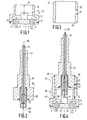
- the base section shown in fig. 1 comprises a metal carrier 3 in which glass lead-throughs 5 with connecting pins 7 are fixed.
- An op- to-electronic light source 9 for example a light-emitting semiconductor diode or a laser, is fixed to the carrier 3.
- the light source 9 is electrically connected with the connection pins 7 by wires not shown.
- the base section 1 also comprises a tubular section 11 placed on the carrier 3 which surrounds the light source 9 and which comprises a first reference surface 13 in the form of a cylinder, the axis 15 of which coincides with the axis of a light beam emitted by the light source.
- This surface can, for example, be obtained by means of an operation as described in US-A-4 298 374 (PHN 9235), in which respect the light beam emitted by the light source 9 can be used for the necessary formation of an image consisting of two circles.
- PPN 9235 the light beam emitted by the light source 9
- the light source 9 and the tubular section 11 which has previously been provided with a cylindrical surface 13 can, for example, be observed simultaneously through a microscope while the tubular section is moved with respect to the carrier until the said surface is accurately coaxial with the light beam emitted by the light source. In this position the tubular section 11 is connected securely to the carrier 3, for example by a welded joint 17 which at the same time provides a hermetic seal between the carrier and the tubular section.
- Fig. 2 shows a longitudinal cross-section of an end section of an optical fibre 21, which in the known manner can consist of a light- conducting core of glass with a relatively high refraction index surrounded by a glass cladding with a relatively low refraction index.
- the fibre 21 is surrounded by a protective layer 23 which is removed over a section of the fibre close to the free end 25.
- This section of the fibre 21 extends through a capillary 27, for example made of quartz, which is fixed by means of an adapter bush 29 in an envelope 31, which surrounds the end section of the fibre 21. All the transitions (fibre- capillary, capillary-adapter bush and adapter bush-envelope) are hermetically sealed.
- the envelope 31 comprises a second reference surface 33 in the form of a cylinder, the axis 35 of which coincides with the axis of the core of the optical fibre 21.
- This surface can be obtained by means of the method described in US-A-4 298 374, or in another known way.
- Fig. 3 shows a longitudinal cross-section of an embodiment of a coupling element 37 with two cavities 39 and 41 positioned coaxially one behind the other and connected to each other.
- the diameter of the inscribed circle of the first cavity 39 is substantially the same as the diameter of the first reference surface 13 of the base section 1 and the diameter of the inscribed circle of the second cavity 41 is substantially the same as the diameter of the second reference surface 33 of the envelope 31.
- the inscribed circles of the two cavities 39 and 41, as well as the reference surfaces 13 and 33 are of the same diameter. This has the advantage that the two cavities 39 and 41 can be made in one operation, which is relatively cheap and offers the certainty that both cavities are precisely coaxial.
- the cavities 39 and 41 in this embodiment are cylindrical in shape so that they can be made in the coupling element 37 in a simple manner, for example by drilling.
- the inscribed circle of each cavity - 39 and 41 follows the inner surface of these cavities over the entire circumference.
- polygonal, for example triangular, cavities 39 and 41 in which respect the inscribed circle touches the circumference of the cavity at only a few points.
- the two cavities 39 and 41 can also have inscribed circles of different diameters. The diameters of the two reference surfaces 13 and 33 must then, of course, also be different.
- the base section 1, the envelope-31 and the coupling element 37 can be combined to form an assembly.
- the base section 1 is pushed with its first reference surface 13 into the first cavity 39 of the coupling element 37 until the carrier 3 connects with the bottom rim of the coupling element and is fixed there, for example by means of a hermetic welded joint 43 running along the entire circumference.
- the second reference surface 33 of the envelope 31 is pushed into the second cavity 41, the optical coupling between the light source 9 and the free end 25 of the fibre 21 being continuously monitored by measuring the quanitity of light emerging at the other end of the fibre (not drawn), while the light source 9 is in operation.
- the position of the envelope 31 is fixed in the coupling element 37, for example by means of one or more spot-welded joints 44.
- the two reference surfaces fit into the cavities substantially free from play. Since the axis of the light beam emitted by the light source 9 coincides with the axis 15 of the first reference surface 13, while the axis of the optical fibre - 21 coincides with the axis 35 of the second reference surface 33, and since the axes of both these reference surfaces are accurately positioned in line with each other by the coupling element 37, the fibre can capture and guide a maximum quantity of the light emitted by the light source.
- the envelope 31 is hermetically secured to the coupling element 37 by means of a welded joint 45 which runs along the top end of the coupling element around its entire circumference.
- the welded joints ensure that the base section 1, the envelope 31 and the coupling element 37 together form a hermetically sealed housing that can be filled with an inert gas or be evacuated if required.
- an aperture 46 is made in the wall of the coupling element (see fig. 3) which is hermetically sealed by welding a metal pin 47 securely into it after evacuation and/or filling with inert gas.
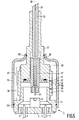
- Fig. 5 shows a longitudinal cross-section of a second an embodiment of an assembly according to the invention which differs in some respects from the embodiment shown in fig. 4. Corresponding parts are indicated by the same reference figures as in figs. 1 to 4.
- the coupling element 37 in this case is not provided with a stop 43.
- the base section 1 is pushed into the first cavity 39 until the carrier 3 connects with the bottom rim of the coupling element 37 and is there secured with, for example, one or more spot-welded joints 49.
- the envelope 31 is pushed into the second cavity 41, the correct axial position being determined in the same manner as described on the basis of fig. 4. In this position the envelope 31 is fixed into the coupling element 37, for example, with one or more spot-welded joints 51.
- the sole purpose of the welded joints 49 and 51 is to prevent axial displacement of the base section 1 and the envelope 31, respectively. They need not constitute a hermetic seal, since a housing wall 53 is placed around the coupling element 37, which is then hermetically connected to the base section 1 and the envelope 31, for example by welded joints 55 and 57.
- a housing wall 53 is placed around the coupling element 37, which is then hermetically connected to the base section 1 and the envelope 31, for example by welded joints 55 and 57.
- an aperture 46 is again provided in the wall of the coupling element 37, an aperture which is later sealed with a metal pin 59 being provided in the housing wall 53.
Landscapes
- Physics & Mathematics (AREA)
- General Physics & Mathematics (AREA)
- Optics & Photonics (AREA)
- Optical Couplings Of Light Guides (AREA)
Applications Claiming Priority (2)
| Application Number | Priority Date | Filing Date | Title |
|---|---|---|---|
| NL8600674 | 1986-03-17 | ||
| NL8600674A NL8600674A (nl) | 1986-03-17 | 1986-03-17 | Samenstel van een hermetisch gesloten huis met een opto-elektronische lichtbron en een lichtgeleidende vezel en werkwijze voor de vervaardiging daarvan. |
Publications (1)
| Publication Number | Publication Date |
|---|---|
| EP0241955A1 true EP0241955A1 (fr) | 1987-10-21 |
Family
ID=19847722
Family Applications (1)
| Application Number | Title | Priority Date | Filing Date |
|---|---|---|---|
| EP87200340A Withdrawn EP0241955A1 (fr) | 1986-03-17 | 1987-02-26 | Coupleur pour une fibre optique avec un élément opto-électronique dans un boîtier étanche et une méthode de fabrication |
Country Status (4)
| Country | Link |
|---|---|
| EP (1) | EP0241955A1 (fr) |
| JP (1) | JPS62226109A (fr) |
| AU (1) | AU590913B2 (fr) |
| NL (1) | NL8600674A (fr) |
Cited By (7)
| Publication number | Priority date | Publication date | Assignee | Title |
|---|---|---|---|---|
| EP0441403A1 (fr) * | 1990-02-08 | 1991-08-14 | Mitsubishi Denki Kabushiki Kaisha | Procédé de fabrication d'un emballage optique |
| EP0619507A1 (fr) * | 1993-04-06 | 1994-10-12 | Koninklijke Philips Electronics N.V. | Dispositif optoélectronique avec couplage entre un composant optoélectronique, en particulier une diode laser, à semi-conducteur, et une fibre optique en verre et procédé de fabrication de celui-ci |
| EP0662622A1 (fr) * | 1993-12-28 | 1995-07-12 | Sumitomo Osaka Cement Co., Ltd. | Structure d'empaquetage pour élément optique et des fibres |
| GB2312526A (en) * | 1996-04-23 | 1997-10-29 | Baillie Hamilton William John | Light emitting device housed in a containment |
| FR2750218A1 (fr) * | 1996-06-20 | 1997-12-26 | Alps Electric Co Ltd | Module pour diode laser |
| US20190129108A1 (en) * | 2017-10-31 | 2019-05-02 | Versalume LLC | Modular Laser Connector Packaging System and Method |
| US10551542B1 (en) | 2018-12-11 | 2020-02-04 | Corning Incorporated | Light modules and devices incorporating light modules |
Families Citing this family (2)
| Publication number | Priority date | Publication date | Assignee | Title |
|---|---|---|---|---|
| JPH0713236Y2 (ja) * | 1989-04-24 | 1995-03-29 | 日本電気株式会社 | 光半導体モジュール |
| JP5410863B2 (ja) * | 2009-04-09 | 2014-02-05 | シチズンホールディングス株式会社 | レーザ光源 |
Citations (1)
| Publication number | Priority date | Publication date | Assignee | Title |
|---|---|---|---|---|
| EP0050051A1 (fr) * | 1980-09-23 | 1982-04-21 | Thomson-Csf | Procédé d'alignement d'une fibre optique avec un composant opto-électronique, adaptateur, et tête de couplage comportant l'utilisation du procédé |
Family Cites Families (1)
| Publication number | Priority date | Publication date | Assignee | Title |
|---|---|---|---|---|
| FR2356167A1 (fr) * | 1976-06-21 | 1978-01-20 | Labo Electronique Physique | Connecteur de fibres optiques a un emetteur ou un recepteur d'energie lumineuse |
-
1986
- 1986-03-17 NL NL8600674A patent/NL8600674A/nl not_active Application Discontinuation
-
1987
- 1987-02-26 EP EP87200340A patent/EP0241955A1/fr not_active Withdrawn
- 1987-03-16 JP JP5909087A patent/JPS62226109A/ja active Pending
- 1987-03-16 AU AU70055/87A patent/AU590913B2/en not_active Ceased
Patent Citations (1)
| Publication number | Priority date | Publication date | Assignee | Title |
|---|---|---|---|---|
| EP0050051A1 (fr) * | 1980-09-23 | 1982-04-21 | Thomson-Csf | Procédé d'alignement d'une fibre optique avec un composant opto-électronique, adaptateur, et tête de couplage comportant l'utilisation du procédé |
Non-Patent Citations (3)
| Title |
|---|
| PATENT ABSTRACTS OF JAPAN, vol. 5, no. 44 (E-50)[716], 24th March 1981; & JP-A-55 166 974 (HITACHI SEISAKUSHO K.K.) 26-12-1980 * |
| PATENT ABSTRACTS OF JAPAN, vol. 6, no. 22 (P-101)[900], 9th February 1982; & JP-A-56 143 405 (NIPPON DENSHIN DENWA KOSHA) 09-11-1981 * |
| REVIEW OF THE ELECTRICAL COMMUNICATION LABORATORIES, vol. 33, no. 3, May 1985, pages 519-527, The Research and Development Headquarters, Tokyo, JP; N. KOJIMA et al.: "Studies on submarine optical fiber cable structure and transmission line configuration" * |
Cited By (14)
| Publication number | Priority date | Publication date | Assignee | Title |
|---|---|---|---|---|
| US5127074A (en) * | 1990-02-08 | 1992-06-30 | Mitsubishi Denki Kabushiki Kaisha | Method of fabricating an optical package |
| EP0441403A1 (fr) * | 1990-02-08 | 1991-08-14 | Mitsubishi Denki Kabushiki Kaisha | Procédé de fabrication d'un emballage optique |
| EP0619507A1 (fr) * | 1993-04-06 | 1994-10-12 | Koninklijke Philips Electronics N.V. | Dispositif optoélectronique avec couplage entre un composant optoélectronique, en particulier une diode laser, à semi-conducteur, et une fibre optique en verre et procédé de fabrication de celui-ci |
| BE1006983A3 (nl) * | 1993-04-06 | 1995-02-07 | Koninkl Philips Electronics Nv | Opto-electronische inrichting met een koppeling tussen een opto-electronische component, in het bijzonder een halfgeleiderdiodelaser, en een optische glasvezel en werkwijze ter vervaardiging van een dergelijke inrichting. |
| US5727105A (en) * | 1993-12-28 | 1998-03-10 | Sumitomo Osaka Cement Co., Ltd. | Package structure for optical element and fibers and composite structure thereof |
| EP0662622A1 (fr) * | 1993-12-28 | 1995-07-12 | Sumitomo Osaka Cement Co., Ltd. | Structure d'empaquetage pour élément optique et des fibres |
| US5613026A (en) * | 1993-12-28 | 1997-03-18 | Sumitomo Osaka Cement Co., Ltd. | Package structure for optical element and fibers and composite structure thereof |
| GB2312526A (en) * | 1996-04-23 | 1997-10-29 | Baillie Hamilton William John | Light emitting device housed in a containment |
| FR2750218A1 (fr) * | 1996-06-20 | 1997-12-26 | Alps Electric Co Ltd | Module pour diode laser |
| US20190129108A1 (en) * | 2017-10-31 | 2019-05-02 | Versalume LLC | Modular Laser Connector Packaging System and Method |
| US10838158B2 (en) | 2017-10-31 | 2020-11-17 | Corning Incorporated | Modular laser connector packaging system and method |
| US10551542B1 (en) | 2018-12-11 | 2020-02-04 | Corning Incorporated | Light modules and devices incorporating light modules |
| US10598840B1 (en) | 2018-12-11 | 2020-03-24 | Corning Incorporated | Light modules and devices incorporating light modules |
| US10768352B2 (en) | 2018-12-11 | 2020-09-08 | Corning Incorporated | Light modules and devices incorporating light modules |
Also Published As
| Publication number | Publication date |
|---|---|
| AU7005587A (en) | 1987-09-24 |
| JPS62226109A (ja) | 1987-10-05 |
| AU590913B2 (en) | 1989-11-23 |
| NL8600674A (nl) | 1987-10-16 |
Similar Documents
| Publication | Publication Date | Title |
|---|---|---|
| EP0104882B1 (fr) | Montages pour le couplage d'une fibre optique | |
| EP0304182B1 (fr) | Transducteur opto-électronique avec un raccord en fibre optique | |
| US5586207A (en) | Methods and assemblies for packaging opto-electronic devices and for coupling optical fibers to the packaged devices | |
| CA1085663A (fr) | Methode de soudage hermetique d'une fibre optique a un boitier metallique | |
| US4615031A (en) | Injection laser packages | |
| US4623220A (en) | Laser to fiber connection | |
| EP0770893B1 (fr) | Sous-support de fermeture de fibre optique et assemblage de traversée hermétique | |
| US4186994A (en) | Arrangement for coupling between an electrooptic device and an optical fiber | |
| EP0100086A2 (fr) | Procédé de fabrication des éléments d'encapsulage pour lasers à injection et éléments d'encapsulage fabriqués par un tel procédé | |
| US4386821A (en) | Opto-electronic coupling head and method for fitting such a head | |
| JPH0227307A (ja) | 光ファイバと半導体レーザダイオード間にカップリングを有するオプトエレクトロニク装置 | |
| CN112782808B (zh) | 光纤装置、用于制造光纤装置的方法及飞机 | |
| US5029968A (en) | Optoelectronic hybrid package assembly including integral, self-aligned fiber optic connector | |
| EP0241955A1 (fr) | Coupleur pour une fibre optique avec un élément opto-électronique dans un boîtier étanche et une méthode de fabrication | |
| EP0404053A2 (fr) | Module optique à semi-conducteur | |
| US4168883A (en) | Arrangement to connect a laser to an optical fiber transmission line | |
| JPH01284807A (ja) | 光ファイバ貫通部とその製造方法 | |
| US4741589A (en) | Coupler for optical waveguides | |
| GB2229856A (en) | Electro-optic transducer and sheet-metal microlens holder | |
| US4787695A (en) | Optical fiber connector and assembly method thereof | |
| CN206682672U (zh) | 光源装置 | |
| JP2005062338A (ja) | 光コネクタの製造方法 | |
| JPS587965B2 (ja) | オプテイカルフアイバ−ノ キミツフウジホウホウ | |
| JP3409437B2 (ja) | 半導体レーザ装置およびその組立方法 | |
| JP3847178B2 (ja) | 光ファイバの気密封止構造とこれを用いた光ファイバアレイ |
Legal Events
| Date | Code | Title | Description |
|---|---|---|---|
| PUAI | Public reference made under article 153(3) epc to a published international application that has entered the european phase |
Free format text: ORIGINAL CODE: 0009012 |
|
| AK | Designated contracting states |
Kind code of ref document: A1 Designated state(s): DE FR GB IT SE |
|
| 17P | Request for examination filed |
Effective date: 19880418 |
|
| 17Q | First examination report despatched |
Effective date: 19891124 |
|
| STAA | Information on the status of an ep patent application or granted ep patent |
Free format text: STATUS: THE APPLICATION IS DEEMED TO BE WITHDRAWN |
|
| 18D | Application deemed to be withdrawn |
Effective date: 19900606 |
|
| RIN1 | Information on inventor provided before grant (corrected) |
Inventor name: KHOE, GIOK DJAN Inventor name: VAN LEEST, JOHANNES HENRICUS FRANCISCUS MARIA Inventor name: KOCK, HENDRIKUS GERARDUS |