EP0242107A2 - Dispositif de mesure dynamique d'un intervalle d'air utilisable avec une machine tournante électrique - Google Patents
Dispositif de mesure dynamique d'un intervalle d'air utilisable avec une machine tournante électrique Download PDFInfo
- Publication number
- EP0242107A2 EP0242107A2 EP87303006A EP87303006A EP0242107A2 EP 0242107 A2 EP0242107 A2 EP 0242107A2 EP 87303006 A EP87303006 A EP 87303006A EP 87303006 A EP87303006 A EP 87303006A EP 0242107 A2 EP0242107 A2 EP 0242107A2
- Authority
- EP
- European Patent Office
- Prior art keywords
- signal
- rotor
- stator
- air gap
- receiver
- Prior art date
- Legal status (The legal status is an assumption and is not a legal conclusion. Google has not performed a legal analysis and makes no representation as to the accuracy of the status listed.)
- Withdrawn
Links
Images


Classifications
-
- G—PHYSICS
- G01—MEASURING; TESTING
- G01S—RADIO DIRECTION-FINDING; RADIO NAVIGATION; DETERMINING DISTANCE OR VELOCITY BY USE OF RADIO WAVES; LOCATING OR PRESENCE-DETECTING BY USE OF THE REFLECTION OR RERADIATION OF RADIO WAVES; ANALOGOUS ARRANGEMENTS USING OTHER WAVES
- G01S15/00—Systems using the reflection or reradiation of acoustic waves, e.g. sonar systems
- G01S15/88—Sonar systems specially adapted for specific applications
-
- G—PHYSICS
- G01—MEASURING; TESTING
- G01S—RADIO DIRECTION-FINDING; RADIO NAVIGATION; DETERMINING DISTANCE OR VELOCITY BY USE OF RADIO WAVES; LOCATING OR PRESENCE-DETECTING BY USE OF THE REFLECTION OR RERADIATION OF RADIO WAVES; ANALOGOUS ARRANGEMENTS USING OTHER WAVES
- G01S15/00—Systems using the reflection or reradiation of acoustic waves, e.g. sonar systems
- G01S15/02—Systems using the reflection or reradiation of acoustic waves, e.g. sonar systems using reflection of acoustic waves
- G01S15/06—Systems determining the position data of a target
- G01S15/08—Systems for measuring distance only
- G01S15/10—Systems for measuring distance only using transmission of interrupted, pulse-modulated waves
- G01S15/14—Systems for measuring distance only using transmission of interrupted, pulse-modulated waves wherein a voltage or current pulse is initiated and terminated in accordance respectively with the pulse transmission and echo reception
Definitions
- This invention relates generally to rotating electrical machinery, and more particularly the invention relates to measurement of the air gap between the rotor and stator of such machinery.
- an infrared beam issuing from the fibers of one bundle, reflecting and entering the fibers of the second bundle, is periodically and partially obscured by fins protruding from cooling slots in the stator.
- a change in the fraction of the fiber obscured by the partial blockage of each fin is a measure of the change in air gap dimensions.
- the present invention is directed to an improved apparatus and a method for measuring air gap by employing sonar technology.
- Sonar or sound navigation ranging, is well known for use in distance measuring.
- U.S.-A-4,240,152 utilizes sonar for providing both distance and location information relative to a moving vehicle.
- U.S.-A-4,470,299 utilizes ultrasonic echo ranging to measure the level of a liquid in an open channel or other liquid container.
- U.S. -A- 4,452,074 utilizes ultrasonic wave propagation for monitoring the moving components of an internal combustion engine. Spectral analysis of reflected signals is employed to determine performance characteristics of the mechanism.
- sound wave transmission and reception means is mounted to provide a continual measurement of air gap by transmitting an ultrasonic pulse across the air gap and receiving a reflection of the pulse.
- the transmission and reception means can be mounted on the stationary stator for detecting changes in air gap due to variations in the rotor, or the transmitter and receiver means can be mounted on the rotor for detecting variations in the stator.
- the transmitter and receiver comprise a single transducer element functioning as a transceiver.
- the round trip pulse propagation time is of sufficient duration to allow the transceiver to damp to its quiescent state for return of the reflected pulse.
- telemetry means is employed in transmitting signals for controlling the transmitter and receiver means and for transmitting signals from the transmitter and receiver means to a gap distance determining computer.
- FIG. 1 is a perspective view partially in section of an electrical generator including air gap monitoring apparatus in accordance with the invention.
- the generator includes a generally cylindrical stator 10 in which a rotor 12 rotates on a shaft 14.
- the stator is shown partially in section to illustrate a sensor array 16 of the air gap monitor.
- the air gap monitor is mounted on the rotor.
- the sensor array 16 is electrically and optically coupled to a central computer 18 through an electrical and optical telemetry coupler shown generally at 20.
- One part of the coupler 20 is mounted to shaft 14 and is electrically connected to the sensor array 16 by means of a twisted pair cable 22.
- the other portion of the coupler 20 is mounted to the stator structure and is periodically aligned with the rotor mounted portion of the coupler as the shaft rotates.
- the stator portion of coupler 20 is connected to the computer 18 through a fiber optic link 24.
- Figure 2 is a section view of a portion of the stator 10 and the rotor 12 and illustrates the positioning of the sensor array 16 between field pole pieces 28 of the rotor.
- the sensor array 16 transmits pulsed ultrasonic waves across the air gap between the rotor and the stator and receives reflections of the pulses. The time required for transmitting a pulse and receiving the reflection thereof is indicative of the air gap spacing.
- the housing for the sensor array 16 is preferably a machined aluminum container having a rectangular cross section, and the aluminum housing is mounted to the pole pieces 28 by suitable means such as a stainless steel support frame or bridge 26.
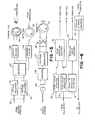
- FIG. 3 is a functional block diagram of one embodiment in which a single ultrasound transducer 30 is employed as a transceiver.
- Transducer 30 is energized by pulse generator 32, and a reflection of the signal from the stator is received by the transducer 30.
- Transducer 30 generates an electrical signal in response to the reflection, and the electrical signal is amplified in amplifier 34 and applied through discriminator 36 (e.g. level sensor) to an output driver 38.
- the output driver 38 converts the discriminator output to a low impedance signal without noise contamination and transmits a stop timing signal or stop pulse from discriminator 36 through the twisted wire pair 40 to the telemetry coupler, as shown in Figure 5.
- the timing circuitry 42 initiates the driver 32 and transmits a start timing signal to deactivate amplifier 34 except during the period of time a reflected signal is received by transducer 30.
- Power for the circuitry on the rotor is provided through a 20 KHz square ware transmitted to transformer 44, converted to dc by full wave rectifier 46 and capacitor 48, and then applied to regulator 50..
- the power supply and the telemetry employed in the described system is known in the prior art.
- Figure 4 is circuitry similar to that of Figure 3 but in which separate transmitting and receiving transducers 31 and 31' are employed. Other components of the circuitry of Figure 4 all correspond to components of the circuitry of Figure 3 as indicated by like reference numerals.
- One air gap sensor has been designed for use for rotor mounting in a 145 MVA, 120 rpm, 12 section, salient pole, hydroelectric generator.
- This machine has a rotor diameter of 32.25 feet, an air gap of 0.705 inch, 504 armature coil slots, and 60 field poles.
- the sonar air gap monitor utilizes a 50 microsecond width burst of pulses driving a 200 KHz piezoelectric acoustic transducer. Both driver and transducer are mounted between two field poles as described with reference to Figure 2, with the transducer access oriented towards the stator, as shown in Figure 2.
- the sensor is scanning the stator.
- the transceiver In order to achieve proper signal-to-noise ratio, it is necessary for the transceiver to have an emission/accep- tance cone sufficiently wide to capture the primary echo.
- the round trip time of the sound pulse and the sensor's tangential velocity correspond to a sweep distance of 1.36 inches and a sweep cone angle of 19.3 degrees. Since the principal lobe of a piezoelectric transducer is typically 20 degrees wide, the sensor for this particular machine is accommodated by a transceiver design. For machines having much higher sweep speeds, it is necessary to employ dual transducers with the transmitter angled forward by the sweep cone half-angle and the receiver similarly angled rearward. Deviations in receiver frequency due to doppler shifting by virtue of receiver motion are not a problem.
- the stator will receive and reflect an upshifted note, about 6% at 20 ° , and the receiver will receive a downshifted note by exactly the same amount.
- the transducer pulse repetition rate depends on the azimuthal resolution required. There is an upper limit which is related to the time for a predecessor pulse's reflections to damp out. For the described embodiment, it can be assumed that the damping time is five times the round trip time. In this case, the maximum rate is 360 Hz, which is downgraded to 330 Hz in order to avoid electronics problems with 6 0 Hz harmonics. Even at this rate the azimuthal resolution for the above machine is 2.2 mechanical degrees or about 14 measurements per section and 165 measurements around the entire machine.
- the number of sensors mounted on a machine depends on whether the stator, rotor, or both are suspected of distorting during machine operation. If the stator alone is suspect, a single sensor mounted on the rotor would suffice. If the rotor or both rotor and stator are suspect, or if there is no idea as to which component may be distorting, the use of three sensors spaced equally around the rotor will permit determination of all combinations as follows. (1) Stator alone distorts: During a complete revolution, all three sensor outputs will show identical, position-dependent variations in air gap, but with 120 mechanical degrees of displacement. (2) Rotor alone distorts: During a complete revolution, all three sensor outputs will show constant, but different, outputs. (3) Both components distort: During a complete revolution, all three SAM outputs will be similar in shape, but of differing amplitudes, as well as 120 out of phase.
- the signals from the output driver 38 are communicated to the computer through any suitable telemetry system, such as the system shown in Figure 5.
- the signals from the sensor modules are applied through lines 52, through optical isolator 54 and MUX selector 56 to an output FM driver 58.
- FM driver 58 continuously drives a transmitting coil 60.
- Coil 60 is coupled to a ferrite antenna 61 which generates a signal that is amplified and converted to light pulses.
- the light pulses are sent to the controller computer through a fiber optic cable.
- Optical signals from the controller are transmitted once per revolution through a coupler 62 to an address latch 63 for sensor selection.
- the transmitted code is stored in address latch 63 and is used to determine which sensor module output to send, and the reception of the code will cause a long pulse to be transmitted by the output driver. This long pulse is detected by the system computer and used to indicate when the rotor is starting a new revolution with another sensor sending data. Power to the sensors is provided using known techniques such as the use of magneto 65, full wave rectifier 66, regulator 67, inverter 68, and transformer 69.
- FIG. 6 is a functional block diagram of the controller interface.
- Optical sensor pulses from the telemetry system are restored to electrical pulses, then monitored by a start pulse detector 70, a stop pulse detector 72, and a start of rotation detector 74.
- echo duration counter 76 is reset and started.
- the echo duration counter 76 is stopped, and the computer is triggered to read the echo duration count.
- the start of rotation detector 74 synchronizes a rotation angle counter 78, which is a phase locked loop circuit that keeps track of the angular position of the rotor.
- Data from the rotation angle counter 78 is read by the computer when the echo duration 76 is read.
- the parallel data codes from the computer which select the desired sensor data, are converted to serial code by converter 80, and the bits of the serial code are then transmitted through a fiber optic cable to the optical transmitter at the generator and then converted back to parallel bits at the transmitter.
- the dynamic air gap measuring device is particularly useful with large rotating electrical machinery as described, but can be employed for any non-contact measurement of the dynamic gap between two surfaces moving with respect to each other.
Landscapes
- Engineering & Computer Science (AREA)
- Radar, Positioning & Navigation (AREA)
- Remote Sensing (AREA)
- Physics & Mathematics (AREA)
- Acoustics & Sound (AREA)
- Computer Networks & Wireless Communication (AREA)
- General Physics & Mathematics (AREA)
- Length Measuring Devices Characterised By Use Of Acoustic Means (AREA)
- Measurement Of Velocity Or Position Using Acoustic Or Ultrasonic Waves (AREA)
- Tests Of Circuit Breakers, Generators, And Electric Motors (AREA)
- Manufacture Of Motors, Generators (AREA)
- Arrangements For Transmission Of Measured Signals (AREA)
Applications Claiming Priority (2)
| Application Number | Priority Date | Filing Date | Title |
|---|---|---|---|
| US850234 | 1986-04-10 | ||
| US06/850,234 US4704906A (en) | 1986-04-10 | 1986-04-10 | Dynamic air gap measuring device for use with rotating electrical machinery |
Publications (2)
| Publication Number | Publication Date |
|---|---|
| EP0242107A2 true EP0242107A2 (fr) | 1987-10-21 |
| EP0242107A3 EP0242107A3 (fr) | 1988-10-05 |
Family
ID=25307612
Family Applications (1)
| Application Number | Title | Priority Date | Filing Date |
|---|---|---|---|
| EP87303006A Withdrawn EP0242107A3 (fr) | 1986-04-10 | 1987-04-07 | Dispositif de mesure dynamique d'un intervalle d'air utilisable avec une machine tournante électrique |
Country Status (6)
| Country | Link |
|---|---|
| US (1) | US4704906A (fr) |
| EP (1) | EP0242107A3 (fr) |
| JP (1) | JPH0638700B2 (fr) |
| BR (1) | BR8701640A (fr) |
| CA (1) | CA1273098A (fr) |
| SE (1) | SE8701477L (fr) |
Cited By (4)
| Publication number | Priority date | Publication date | Assignee | Title |
|---|---|---|---|---|
| WO1995004285A1 (fr) * | 1993-07-30 | 1995-02-09 | Itt Industries, Inc. | Detecteur dynamique d'entrefer |
| WO2015050658A1 (fr) * | 2013-10-02 | 2015-04-09 | Siemens Energy, Inc. | Mesure de l'espace de l'extrémité de la pale in situ pour turbines |
| US9068906B2 (en) | 2013-10-02 | 2015-06-30 | Siemens Energy, Inc. | Turbine blade-mounted sensor fixture for tip gap measurement |
| US10222200B2 (en) | 2017-05-12 | 2019-03-05 | Siemens Energy, Inc. | Contactless, blade-tip clearance measurement for turbines |
Families Citing this family (20)
| Publication number | Priority date | Publication date | Assignee | Title |
|---|---|---|---|---|
| US5159835A (en) * | 1986-10-29 | 1992-11-03 | Westinghouse Electric Corp. | Check valve testing system |
| US5154080A (en) * | 1986-10-29 | 1992-10-13 | Westinghouse Electric Corp. | Integrated check valve testing system |
| US5385050A (en) * | 1992-04-07 | 1995-01-31 | Northrop Grumman Corporation | Gap measurement for shim manufacture |
| US5415046A (en) * | 1992-10-07 | 1995-05-16 | Guinon; Walter J. | Time gated listening device for machinery analysis |
| CA2127135A1 (fr) * | 1994-06-30 | 1995-12-31 | Bryan P. Mclaughlin | Dispositif et methode pour determiner le positionnement optimal des elements internes et externes d'une machine rotative |
| US6489884B1 (en) | 1996-01-30 | 2002-12-03 | Skf Condition Monitoring | Apparatus and method for the remote monitoring of machine condition |
| US5845230A (en) * | 1996-01-30 | 1998-12-01 | Skf Condition Monitoring | Apparatus and method for the remote monitoring of machine condition |
| SE516952C2 (sv) * | 2000-09-04 | 2002-03-26 | Johansson Ab C E | Vinkelgivare |
| EP1617174A1 (fr) * | 2004-07-12 | 2006-01-18 | Siemens Aktiengesellschaft | Détermination de jeu radial |
| US20060167638A1 (en) * | 2004-11-04 | 2006-07-27 | Murphy Jonathan D M | Data collector with wireless server connection |
| US8137058B2 (en) * | 2008-03-10 | 2012-03-20 | General Electric Company | Method and apparatus for determining clearance between moving and static members in a machine |
| CN102405582B (zh) * | 2009-04-24 | 2014-10-29 | 阿尔斯通再生能源技术公司 | 包括转子、定子和在转子与定子之间的空气间隙的电机 |
| US8536813B2 (en) | 2010-05-19 | 2013-09-17 | The Invention Science Fund I Llc | Motor with rotor-mounted control circuitry |
| US8466649B2 (en) | 2010-05-19 | 2013-06-18 | The Invention Science Fund I Llc | Heat removal from motor components |
| EP2866939B1 (fr) | 2012-06-29 | 2020-10-14 | Metso Minerals, Inc. | Captage de position de rotor et la commande pour un concasseur à impact |
| EP2690422B1 (fr) * | 2012-07-25 | 2020-04-08 | Ansaldo Energia IP UK Limited | Procédé de surveillance de machines avec arbres rotatifs |
| DE102014212412A1 (de) * | 2014-06-27 | 2015-12-31 | Siemens Aktiengesellschaft | Abstandsmessverfahren und Abstandsmesseinrichtung |
| CN107677214A (zh) * | 2017-11-03 | 2018-02-09 | 北京金风科创风电设备有限公司 | 发电机气隙的实时检测系统、方法和风力发电机组 |
| CN109883341B (zh) * | 2019-03-28 | 2020-12-04 | 中广核核电运营有限公司 | 一种用于励磁机的测距装置及其测距方法 |
| CN110071607B (zh) * | 2019-04-23 | 2021-01-26 | 中广核核电运营有限公司 | 发电机检修机器人 |
Family Cites Families (11)
| Publication number | Priority date | Publication date | Assignee | Title |
|---|---|---|---|---|
| US3760414A (en) * | 1971-10-22 | 1973-09-18 | Sperry Rand Corp | Base band vehicle safety apparatus |
| DE2654020A1 (de) * | 1976-11-27 | 1978-06-01 | Bbc Brown Boveri & Cie | Mess- und/oder ueberwachungseinrichtung fuer spaltaenderungen |
| DE2730508A1 (de) * | 1977-07-06 | 1979-01-25 | Bbc Brown Boveri & Cie | Mess- und/oder ueberwachungseinrichtung fuer aenderungen der spaltweite zwischen relativ zueinander bewegbaren bauelementen |
| GB1598405A (en) * | 1978-03-08 | 1981-09-23 | Nat Res Dev | Proximity indicating sonar equipment |
| US4368641A (en) * | 1981-01-30 | 1983-01-18 | Powers Manufacturing, Inc. | Out-of-round detector |
| FR2506455A1 (fr) * | 1981-05-21 | 1982-11-26 | Elf Aquitaine | Systeme d'analyse des mouvements vibratoires d'une machine tournante |
| US4413519A (en) * | 1981-07-29 | 1983-11-08 | Westinghouse Electric Corp. | Turbine blade vibration detection apparatus |
| US4452074A (en) * | 1981-09-04 | 1984-06-05 | Shelomentsev Timofei I | Method of and apparatus for monitoring the performance of internal combustion engine mechanisms |
| US4422333A (en) * | 1982-04-29 | 1983-12-27 | The Franklin Institute | Method and apparatus for detecting and identifying excessively vibrating blades of a turbomachine |
| US4472793A (en) * | 1982-05-25 | 1984-09-18 | Eastport International, Inc. | Data selector circuit with channel skipper for data acquisition system |
| US4464935A (en) * | 1983-05-09 | 1984-08-14 | General Electric Company | Shaft vibration evaluation |
-
1986
- 1986-04-10 US US06/850,234 patent/US4704906A/en not_active Expired - Fee Related
-
1987
- 1987-04-07 EP EP87303006A patent/EP0242107A3/fr not_active Withdrawn
- 1987-04-08 BR BR8701640A patent/BR8701640A/pt unknown
- 1987-04-09 JP JP8788887A patent/JPH0638700B2/ja not_active Expired - Lifetime
- 1987-04-09 SE SE8701477A patent/SE8701477L/ not_active Application Discontinuation
- 1987-04-09 CA CA000534294A patent/CA1273098A/fr not_active Expired
Cited By (6)
| Publication number | Priority date | Publication date | Assignee | Title |
|---|---|---|---|---|
| WO1995004285A1 (fr) * | 1993-07-30 | 1995-02-09 | Itt Industries, Inc. | Detecteur dynamique d'entrefer |
| WO2015050658A1 (fr) * | 2013-10-02 | 2015-04-09 | Siemens Energy, Inc. | Mesure de l'espace de l'extrémité de la pale in situ pour turbines |
| US9068906B2 (en) | 2013-10-02 | 2015-06-30 | Siemens Energy, Inc. | Turbine blade-mounted sensor fixture for tip gap measurement |
| US9513117B2 (en) | 2013-10-02 | 2016-12-06 | Siemens Energy, Inc. | Situ blade mounted tip gap measurement for turbines |
| US9581440B2 (en) | 2013-10-02 | 2017-02-28 | Siemens Energy, Inc. | In-situ blade-mounted optical camera inspected systems for turbine engines |
| US10222200B2 (en) | 2017-05-12 | 2019-03-05 | Siemens Energy, Inc. | Contactless, blade-tip clearance measurement for turbines |
Also Published As
| Publication number | Publication date |
|---|---|
| SE8701477D0 (sv) | 1987-04-09 |
| CA1273098A (fr) | 1990-08-21 |
| US4704906A (en) | 1987-11-10 |
| BR8701640A (pt) | 1988-01-12 |
| SE8701477L (sv) | 1987-10-11 |
| JPH0638700B2 (ja) | 1994-05-18 |
| JPS63129830A (ja) | 1988-06-02 |
| EP0242107A3 (fr) | 1988-10-05 |
Similar Documents
| Publication | Publication Date | Title |
|---|---|---|
| US4704906A (en) | Dynamic air gap measuring device for use with rotating electrical machinery | |
| EP0024495B1 (fr) | Système de ligne de retard d'impulsions acoustiques pour la mesure de distances le long d'un fil magnétostrictif | |
| US4678993A (en) | Distance measuring device operating with torsional ultrasonic waves detected without mode conversion | |
| EP0442985B1 (fr) | Transducteur magnetostrictif stimulateur de signal a tete compacte | |
| US4089227A (en) | Apparatus for measuring the radial dimensions of a cylindrical tube by ultrasonics | |
| US5998991A (en) | Pickupless magnetostrictive position measurement apparatus | |
| US5359898A (en) | Hydrogen damage confirmation with EMATs | |
| JPH02103423A (ja) | 羽根の通過を検出する方法及び装置 | |
| EP0091826A2 (fr) | Capteur à fibre optique amélioré pour détecter de très petits déplacements d'une surface | |
| US2408035A (en) | Observation system | |
| EP0212899B1 (fr) | Essai de matériaux aux ultra-sons | |
| JPH11125688A (ja) | 原子炉振動監視装置 | |
| US4722226A (en) | Acoustic monitor for rotary electrical machinery | |
| US4845990A (en) | Ultrasonic mine survey probe | |
| US4083255A (en) | Hydro-optic vibration detector | |
| JP3169534B2 (ja) | 浸水検出方法 | |
| CN101545973B (zh) | 距离测量系统及方法 | |
| US4516427A (en) | Quartz rate sensor | |
| US3540279A (en) | Acoustic sensing system | |
| JPH07311184A (ja) | 超音波伝播時間測定用のセンサ及びこれを用いた超音波伝播時間測定方法 | |
| EP0075617A1 (fr) | Dispositif de mesure de distance par ultrasons | |
| SU987393A1 (ru) | Ультразвуковой измеритель скорости течений | |
| SU879440A1 (ru) | Способ измерени скорости ультразвука | |
| JPH07174741A (ja) | 超音波音速計測装置 | |
| JPS6394184A (ja) | 超音波変位検出装置 |
Legal Events
| Date | Code | Title | Description |
|---|---|---|---|
| PUAI | Public reference made under article 153(3) epc to a published international application that has entered the european phase |
Free format text: ORIGINAL CODE: 0009012 |
|
| AK | Designated contracting states |
Kind code of ref document: A2 Designated state(s): AT BE CH DE ES FR GB GR IT LI LU NL SE |
|
| PUAL | Search report despatched |
Free format text: ORIGINAL CODE: 0009013 |
|
| AK | Designated contracting states |
Kind code of ref document: A3 Designated state(s): AT BE CH DE ES FR GB GR IT LI LU NL SE |
|
| 17P | Request for examination filed |
Effective date: 19890314 |
|
| 17Q | First examination report despatched |
Effective date: 19910829 |
|
| STAA | Information on the status of an ep patent application or granted ep patent |
Free format text: STATUS: THE APPLICATION IS DEEMED TO BE WITHDRAWN |
|
| 18D | Application deemed to be withdrawn |
Effective date: 19920109 |
|
| RIN1 | Information on inventor provided before grant (corrected) |
Inventor name: ROSS, JAMES M. Inventor name: CHURCHILL, THOMAS LYNN |