EP0242127A2 - Système pour commander l'embrayage d'un véhicule - Google Patents
Système pour commander l'embrayage d'un véhicule Download PDFInfo
- Publication number
- EP0242127A2 EP0242127A2 EP87303097A EP87303097A EP0242127A2 EP 0242127 A2 EP0242127 A2 EP 0242127A2 EP 87303097 A EP87303097 A EP 87303097A EP 87303097 A EP87303097 A EP 87303097A EP 0242127 A2 EP0242127 A2 EP 0242127A2
- Authority
- EP
- European Patent Office
- Prior art keywords
- clutch
- vehicle
- speed
- vehicle speed
- section
- Prior art date
- Legal status (The legal status is an assumption and is not a legal conclusion. Google has not performed a legal analysis and makes no representation as to the accuracy of the status listed.)
- Granted
Links
Images




Classifications
-
- F—MECHANICAL ENGINEERING; LIGHTING; HEATING; WEAPONS; BLASTING
- F16—ENGINEERING ELEMENTS AND UNITS; GENERAL MEASURES FOR PRODUCING AND MAINTAINING EFFECTIVE FUNCTIONING OF MACHINES OR INSTALLATIONS; THERMAL INSULATION IN GENERAL
- F16D—COUPLINGS FOR TRANSMITTING ROTATION; CLUTCHES; BRAKES
- F16D48/00—External control of clutches
- F16D48/06—Control by electric or electronic means, e.g. of fluid pressure
-
- B—PERFORMING OPERATIONS; TRANSPORTING
- B60—VEHICLES IN GENERAL
- B60W—CONJOINT CONTROL OF VEHICLE SUB-UNITS OF DIFFERENT TYPE OR DIFFERENT FUNCTION; CONTROL SYSTEMS SPECIALLY ADAPTED FOR HYBRID VEHICLES; ROAD VEHICLE DRIVE CONTROL SYSTEMS FOR PURPOSES NOT RELATED TO THE CONTROL OF A PARTICULAR SUB-UNIT
- B60W10/00—Conjoint control of vehicle sub-units of different type or different function
- B60W10/02—Conjoint control of vehicle sub-units of different type or different function including control of driveline clutches
-
- B—PERFORMING OPERATIONS; TRANSPORTING
- B60—VEHICLES IN GENERAL
- B60W—CONJOINT CONTROL OF VEHICLE SUB-UNITS OF DIFFERENT TYPE OR DIFFERENT FUNCTION; CONTROL SYSTEMS SPECIALLY ADAPTED FOR HYBRID VEHICLES; ROAD VEHICLE DRIVE CONTROL SYSTEMS FOR PURPOSES NOT RELATED TO THE CONTROL OF A PARTICULAR SUB-UNIT
- B60W10/00—Conjoint control of vehicle sub-units of different type or different function
- B60W10/04—Conjoint control of vehicle sub-units of different type or different function including control of propulsion units
- B60W10/06—Conjoint control of vehicle sub-units of different type or different function including control of propulsion units including control of combustion engines
-
- B—PERFORMING OPERATIONS; TRANSPORTING
- B60—VEHICLES IN GENERAL
- B60W—CONJOINT CONTROL OF VEHICLE SUB-UNITS OF DIFFERENT TYPE OR DIFFERENT FUNCTION; CONTROL SYSTEMS SPECIALLY ADAPTED FOR HYBRID VEHICLES; ROAD VEHICLE DRIVE CONTROL SYSTEMS FOR PURPOSES NOT RELATED TO THE CONTROL OF A PARTICULAR SUB-UNIT
- B60W10/00—Conjoint control of vehicle sub-units of different type or different function
- B60W10/10—Conjoint control of vehicle sub-units of different type or different function including control of change-speed gearings
- B60W10/101—Infinitely variable gearings
- B60W10/107—Infinitely variable gearings with endless flexible members
-
- B—PERFORMING OPERATIONS; TRANSPORTING
- B60—VEHICLES IN GENERAL
- B60W—CONJOINT CONTROL OF VEHICLE SUB-UNITS OF DIFFERENT TYPE OR DIFFERENT FUNCTION; CONTROL SYSTEMS SPECIALLY ADAPTED FOR HYBRID VEHICLES; ROAD VEHICLE DRIVE CONTROL SYSTEMS FOR PURPOSES NOT RELATED TO THE CONTROL OF A PARTICULAR SUB-UNIT
- B60W30/00—Purposes of road vehicle drive control systems not related to the control of a particular sub-unit, e.g. of systems using conjoint control of vehicle sub-units
- B60W30/18—Propelling the vehicle
- B60W30/18009—Propelling the vehicle related to particular drive situations
- B60W30/18072—Coasting
-
- F—MECHANICAL ENGINEERING; LIGHTING; HEATING; WEAPONS; BLASTING
- F16—ENGINEERING ELEMENTS AND UNITS; GENERAL MEASURES FOR PRODUCING AND MAINTAINING EFFECTIVE FUNCTIONING OF MACHINES OR INSTALLATIONS; THERMAL INSULATION IN GENERAL
- F16D—COUPLINGS FOR TRANSMITTING ROTATION; CLUTCHES; BRAKES
- F16D48/00—External control of clutches
- F16D48/06—Control by electric or electronic means, e.g. of fluid pressure
- F16D48/064—Control of electrically or electromagnetically actuated clutches
-
- F—MECHANICAL ENGINEERING; LIGHTING; HEATING; WEAPONS; BLASTING
- F16—ENGINEERING ELEMENTS AND UNITS; GENERAL MEASURES FOR PRODUCING AND MAINTAINING EFFECTIVE FUNCTIONING OF MACHINES OR INSTALLATIONS; THERMAL INSULATION IN GENERAL
- F16H—GEARING
- F16H61/00—Control functions within control units of change-speed- or reversing-gearings for conveying rotary motion ; Control of exclusively fluid gearing, friction gearing, gearings with endless flexible members or other particular types of gearing
- F16H61/66—Control functions within control units of change-speed- or reversing-gearings for conveying rotary motion ; Control of exclusively fluid gearing, friction gearing, gearings with endless flexible members or other particular types of gearing specially adapted for continuously variable gearings
-
- B—PERFORMING OPERATIONS; TRANSPORTING
- B60—VEHICLES IN GENERAL
- B60W—CONJOINT CONTROL OF VEHICLE SUB-UNITS OF DIFFERENT TYPE OR DIFFERENT FUNCTION; CONTROL SYSTEMS SPECIALLY ADAPTED FOR HYBRID VEHICLES; ROAD VEHICLE DRIVE CONTROL SYSTEMS FOR PURPOSES NOT RELATED TO THE CONTROL OF A PARTICULAR SUB-UNIT
- B60W2552/00—Input parameters relating to infrastructure
- B60W2552/15—Road slope, i.e. the inclination of a road segment in the longitudinal direction
-
- F—MECHANICAL ENGINEERING; LIGHTING; HEATING; WEAPONS; BLASTING
- F16—ENGINEERING ELEMENTS AND UNITS; GENERAL MEASURES FOR PRODUCING AND MAINTAINING EFFECTIVE FUNCTIONING OF MACHINES OR INSTALLATIONS; THERMAL INSULATION IN GENERAL
- F16D—COUPLINGS FOR TRANSMITTING ROTATION; CLUTCHES; BRAKES
- F16D2500/00—External control of clutches by electric or electronic means
- F16D2500/10—System to be controlled
- F16D2500/102—Actuator
- F16D2500/1021—Electrical type
- F16D2500/1022—Electromagnet
-
- F—MECHANICAL ENGINEERING; LIGHTING; HEATING; WEAPONS; BLASTING
- F16—ENGINEERING ELEMENTS AND UNITS; GENERAL MEASURES FOR PRODUCING AND MAINTAINING EFFECTIVE FUNCTIONING OF MACHINES OR INSTALLATIONS; THERMAL INSULATION IN GENERAL
- F16D—COUPLINGS FOR TRANSMITTING ROTATION; CLUTCHES; BRAKES
- F16D2500/00—External control of clutches by electric or electronic means
- F16D2500/10—System to be controlled
- F16D2500/108—Gear
- F16D2500/1088—CVT
-
- F—MECHANICAL ENGINEERING; LIGHTING; HEATING; WEAPONS; BLASTING
- F16—ENGINEERING ELEMENTS AND UNITS; GENERAL MEASURES FOR PRODUCING AND MAINTAINING EFFECTIVE FUNCTIONING OF MACHINES OR INSTALLATIONS; THERMAL INSULATION IN GENERAL
- F16D—COUPLINGS FOR TRANSMITTING ROTATION; CLUTCHES; BRAKES
- F16D2500/00—External control of clutches by electric or electronic means
- F16D2500/30—Signal inputs
- F16D2500/306—Signal inputs from the engine
- F16D2500/3067—Speed of the engine
-
- F—MECHANICAL ENGINEERING; LIGHTING; HEATING; WEAPONS; BLASTING
- F16—ENGINEERING ELEMENTS AND UNITS; GENERAL MEASURES FOR PRODUCING AND MAINTAINING EFFECTIVE FUNCTIONING OF MACHINES OR INSTALLATIONS; THERMAL INSULATION IN GENERAL
- F16D—COUPLINGS FOR TRANSMITTING ROTATION; CLUTCHES; BRAKES
- F16D2500/00—External control of clutches by electric or electronic means
- F16D2500/30—Signal inputs
- F16D2500/308—Signal inputs from the transmission
- F16D2500/3081—Signal inputs from the transmission from the input shaft
- F16D2500/30816—Speed of the input shaft
-
- F—MECHANICAL ENGINEERING; LIGHTING; HEATING; WEAPONS; BLASTING
- F16—ENGINEERING ELEMENTS AND UNITS; GENERAL MEASURES FOR PRODUCING AND MAINTAINING EFFECTIVE FUNCTIONING OF MACHINES OR INSTALLATIONS; THERMAL INSULATION IN GENERAL
- F16D—COUPLINGS FOR TRANSMITTING ROTATION; CLUTCHES; BRAKES
- F16D2500/00—External control of clutches by electric or electronic means
- F16D2500/30—Signal inputs
- F16D2500/308—Signal inputs from the transmission
- F16D2500/3082—Signal inputs from the transmission from the output shaft
- F16D2500/30825—Speed of the output shaft
-
- F—MECHANICAL ENGINEERING; LIGHTING; HEATING; WEAPONS; BLASTING
- F16—ENGINEERING ELEMENTS AND UNITS; GENERAL MEASURES FOR PRODUCING AND MAINTAINING EFFECTIVE FUNCTIONING OF MACHINES OR INSTALLATIONS; THERMAL INSULATION IN GENERAL
- F16D—COUPLINGS FOR TRANSMITTING ROTATION; CLUTCHES; BRAKES
- F16D2500/00—External control of clutches by electric or electronic means
- F16D2500/30—Signal inputs
- F16D2500/31—Signal inputs from the vehicle
- F16D2500/3108—Vehicle speed
-
- F—MECHANICAL ENGINEERING; LIGHTING; HEATING; WEAPONS; BLASTING
- F16—ENGINEERING ELEMENTS AND UNITS; GENERAL MEASURES FOR PRODUCING AND MAINTAINING EFFECTIVE FUNCTIONING OF MACHINES OR INSTALLATIONS; THERMAL INSULATION IN GENERAL
- F16D—COUPLINGS FOR TRANSMITTING ROTATION; CLUTCHES; BRAKES
- F16D2500/00—External control of clutches by electric or electronic means
- F16D2500/30—Signal inputs
- F16D2500/314—Signal inputs from the user
- F16D2500/31406—Signal inputs from the user input from pedals
- F16D2500/3144—Accelerator pedal position
- F16D2500/31453—Accelerator pedal position threshold, e.g. switch
-
- F—MECHANICAL ENGINEERING; LIGHTING; HEATING; WEAPONS; BLASTING
- F16—ENGINEERING ELEMENTS AND UNITS; GENERAL MEASURES FOR PRODUCING AND MAINTAINING EFFECTIVE FUNCTIONING OF MACHINES OR INSTALLATIONS; THERMAL INSULATION IN GENERAL
- F16D—COUPLINGS FOR TRANSMITTING ROTATION; CLUTCHES; BRAKES
- F16D2500/00—External control of clutches by electric or electronic means
- F16D2500/30—Signal inputs
- F16D2500/314—Signal inputs from the user
- F16D2500/3146—Signal inputs from the user input from levers
- F16D2500/31466—Gear lever
-
- F—MECHANICAL ENGINEERING; LIGHTING; HEATING; WEAPONS; BLASTING
- F16—ENGINEERING ELEMENTS AND UNITS; GENERAL MEASURES FOR PRODUCING AND MAINTAINING EFFECTIVE FUNCTIONING OF MACHINES OR INSTALLATIONS; THERMAL INSULATION IN GENERAL
- F16D—COUPLINGS FOR TRANSMITTING ROTATION; CLUTCHES; BRAKES
- F16D2500/00—External control of clutches by electric or electronic means
- F16D2500/50—Problem to be solved by the control system
- F16D2500/502—Relating the clutch
- F16D2500/50227—Control of clutch to control engine
-
- F—MECHANICAL ENGINEERING; LIGHTING; HEATING; WEAPONS; BLASTING
- F16—ENGINEERING ELEMENTS AND UNITS; GENERAL MEASURES FOR PRODUCING AND MAINTAINING EFFECTIVE FUNCTIONING OF MACHINES OR INSTALLATIONS; THERMAL INSULATION IN GENERAL
- F16D—COUPLINGS FOR TRANSMITTING ROTATION; CLUTCHES; BRAKES
- F16D2500/00—External control of clutches by electric or electronic means
- F16D2500/50—Problem to be solved by the control system
- F16D2500/508—Relating driving conditions
- F16D2500/50825—Hill climbing or descending
-
- F—MECHANICAL ENGINEERING; LIGHTING; HEATING; WEAPONS; BLASTING
- F16—ENGINEERING ELEMENTS AND UNITS; GENERAL MEASURES FOR PRODUCING AND MAINTAINING EFFECTIVE FUNCTIONING OF MACHINES OR INSTALLATIONS; THERMAL INSULATION IN GENERAL
- F16D—COUPLINGS FOR TRANSMITTING ROTATION; CLUTCHES; BRAKES
- F16D2500/00—External control of clutches by electric or electronic means
- F16D2500/50—Problem to be solved by the control system
- F16D2500/508—Relating driving conditions
- F16D2500/50858—Selecting a Mode of operation
-
- F—MECHANICAL ENGINEERING; LIGHTING; HEATING; WEAPONS; BLASTING
- F16—ENGINEERING ELEMENTS AND UNITS; GENERAL MEASURES FOR PRODUCING AND MAINTAINING EFFECTIVE FUNCTIONING OF MACHINES OR INSTALLATIONS; THERMAL INSULATION IN GENERAL
- F16D—COUPLINGS FOR TRANSMITTING ROTATION; CLUTCHES; BRAKES
- F16D2500/00—External control of clutches by electric or electronic means
- F16D2500/70—Details about the implementation of the control system
- F16D2500/704—Output parameters from the control unit; Target parameters to be controlled
- F16D2500/70402—Actuator parameters
- F16D2500/70418—Current
-
- F—MECHANICAL ENGINEERING; LIGHTING; HEATING; WEAPONS; BLASTING
- F16—ENGINEERING ELEMENTS AND UNITS; GENERAL MEASURES FOR PRODUCING AND MAINTAINING EFFECTIVE FUNCTIONING OF MACHINES OR INSTALLATIONS; THERMAL INSULATION IN GENERAL
- F16H—GEARING
- F16H61/00—Control functions within control units of change-speed- or reversing-gearings for conveying rotary motion ; Control of exclusively fluid gearing, friction gearing, gearings with endless flexible members or other particular types of gearing
- F16H61/21—Providing engine brake control
-
- Y—GENERAL TAGGING OF NEW TECHNOLOGICAL DEVELOPMENTS; GENERAL TAGGING OF CROSS-SECTIONAL TECHNOLOGIES SPANNING OVER SEVERAL SECTIONS OF THE IPC; TECHNICAL SUBJECTS COVERED BY FORMER USPC CROSS-REFERENCE ART COLLECTIONS [XRACs] AND DIGESTS
- Y10—TECHNICAL SUBJECTS COVERED BY FORMER USPC
- Y10S—TECHNICAL SUBJECTS COVERED BY FORMER USPC CROSS-REFERENCE ART COLLECTIONS [XRACs] AND DIGESTS
- Y10S477/00—Interrelated power delivery controls, including engine control
- Y10S477/901—Control signal is slope
Definitions
- the present invention relates to a system for controlling a clutch for an automatic transmission of a motor vehicle.
- An automobile provided with a continuously variable belt-drive transmission with an electromagnetic clutch is disclosed in EP-A 151038.
- the electromagnetic clutch of the transmission is controlled by a control system to provide various operational modes such as a starting mode of a vehicle, reverse excitation mode, drag mode, mode of lock-up engagement.
- One of the modes is selected in accordance with a position of a selector lever and driving conditions to control the electromagnetic clutch.
- the vehicle speed at which the clutch is engaged is set at a relatively high level so as to enhance coasting of the vehicle. Accordingly, when the vehicle coasts downhill at a speed lower than the cluth engaging speed, the vehicle may accelerate although the accelerator pedal is not depressed.
- Such acceleration of the vehicle downhill is not critical in ordinary conditions. However, for example, on a snowy or icy hill it is desirable that the clutch is engaged in the low vehicle speed range so as to effect the engine braking and prevent coasting. However the clutch-engaging vehicle speed is set at such a high level in the conventional system, that the vehicle tends to accelerate up to a high speed without engine braking.
- Japanese Patent Laid Open 60-157930 proposes a control system wherein once the vehicle speed reaches a speed for the engagement of, the clutch while the accelerator pedal is released (i.e. the vehicle is coasting downhill), the clutch engaging vehicle speed at which the clutch is engaged is changed to a lower speed. Thus, engine braking is effective at a low vehicle speed.
- the present invention seeks to provide a system for controlling an electromagnetic clutch wherein sufficient engine braking effect can be achieved when driving downhill even at relatively low vehicle speed.
- crankshaft 10 of an engine 1 is operatively connected to an electromagnetic powder clutch 2 so as to transmit the power of the engine 1 to a continuously variable belt-drive automatic transmission 4 through a selector mechanism 3.
- the output of the belt-drive transmission 4 is transmitted to axles 8 of vehicle driving wheels 9 through an output shaft 13, a pair of intermediate reduction gears 5, an intermediate shaft 6, and a differential 7.
- the electromagnetic powder clutch 2 comprises an annular drive member 2a connected to crankshaft 10 of the engine 1, a driven member 2b secured to an input shaft 11 of the transmission 4, and a magnetizing coil 2c provided in the driven member 2b. Magnetic powder is provided in a gap between the drive member 2a and driven member 2b. When the magnetizing coil 2c is excited by the clutch current, driven member 2b is magnetized to produce a magnetic flux passing through the drive member 2a. The magnetic powder is aggregated in the gap by the magnetic flux and the driven member 2b is engaged with the drive member 2a by the powder. On the other hand, when the clutch current is cut off, the drive and driven members 2a and 2b are disengaged from one another.
- the selector mechanism 3 is provided between the input shaft 11 and a main shaft 12.
- the selector mechanism 3 is provided with a synchromesh mechanism comprising gears, hub, and sleeve for connecting the input shaft 11 and the main shaft 12 to selectively provide a driving position (D-range) and a reverse driving position (R-range)
- the continuously variable belt-drive automatic transmission 4 has the main shaft 12 and the output shaft 13 provided in parallel with the main shaft 12.
- a drive pulley 14 provided with a hydraulic cylinder 14a is mounted on the main shaft 12.
- a driven pulley 15 provided with a hydraulic cylinder 15a is mounted on the output shaft 13.
- a drive belt 16 engages with the drive pulley 14 and the driven pulley 15.
- Hydraulic cylinders 14a and 15a are communicated with an oil hydraulic control circuit 17.
- the hydraulic control circuit 17 is responsive to vehicle speed, engine speed and throttle valve position for controlling the amount of oil supplied to the cylinders 14a and 15a.
- the pulleys 14 and 15 are operated by compressive forces of cylinders so that the running diameter of belt 16 is varied to infinitely change the transmission ratio.
- An electronic control system for the clutch 2 and the, belt-drive transmission 4 has an engine speed sensor 19, and rotating speed sensors 21 and 22 for respectively sensing speeds of drive pulley 14 and the driven pulley 15.
- a choke switch 24 produces an output signal when a choke valve of the engine 1 is closed, and an air conditioner switch 23 produces an output signal during operation of the air conditioner.
- a selector lever 25 connected to the selector mechanism is provided with a select position sensor 26 for sensing the drive position D and reverse position R.
- An accelerator pedal switch 28 is provided for sensing the depression of an accelerator pedal 27, and a throttle position sensor 29 is provided.
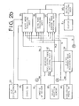
- Output signals of the sensors and pulses of the switches are applied to an electronic control unit 20 which produces a clutch current control signal to the clutch 2 and a control signal for controlling the transmission ratio (i) and a line pressure control singal to the control circuit 17.
- a transmission ratio changing speed control section 30 is applied with a drive pulley speed signal N of the sensor 21, driven pulley speed signal Ns of the sensor 22, and throttle position signal e of the sensor 29 to produce the transmission ratio control signal dependent on a desired transmission ratio changing speed di/dt.
- a line pressure control section 31 is applied with an engine speed signal Ne of the sensor 19, throttle position signal ⁇ of the sensor 29, actual transmission speed ratio signal i (N S /N P ) of the transmission ratio changing speed control section 30 to produce the line pressure control signal dependent on a desired line pressure.
- a reverse excitation mode deciding section 32 is applied with engine speed signal Ne of the sensor 19 and drive position signal of the select position sensor 26.
- the reverse excitation mode deciding section 32 produces a reverse excitation signal which is applied to an output deciding section 33, so that a small reverse current flows in the clutch 2 to release the clutch completely.
- a clutch current mode deciding section 34 is applied with signals from the reverse excitation mode deciding section 32 and accelerator pedal switch 28, and vehicle speed signal V from driven pulley speed sensor 22 for deciding driving conditions such as starting mode to produce output signals.
- the output signals are applied to a start mode providing section 35, drag mode providing section 36, and clutch lock-up engage mode providing section 37.
- the start mode providing section 35 decides clutch current of starting characteristic dependent on the engine speed Ne at ordinary start or at closing of the choke switch. 24 or air conditioner switch 23.
- the starting characteristic is corrected by signals from the throttle valve opening degree e, vehicle speed V, and driving positions of D-range and R-range.
- the drag mode providing section 36 decides a small drag current when the accelerator pedal 27 is released at a low speed in each drive position for providing a drag torque to the clutch 2 for the smooth start of the vehicle.
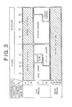
- the clutch lock-up engage mode providing section 37 decides a lock-up current in response to the vehicle speed V and throttle opening degree 8 at each drive position for entirely engaging the clutch 2. Outputs of sections 35, 36 and 37 are applied to the output deciding section 33 to control the clutch current. A range of each mode is shown in Fig. 3.
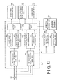
- the clutch current mode deciding section 34 is provided with an accelerator pedal depressed mode section 40 and an accelerator pedal released mode section 41, each applied with output signals of throttle valve opening degree 6, vehicle speed V and reverse excitation mode deciding section 32.
- the accelerator pedal depressed mode section 40 is connected to a start mode deciding section 42 and lock-up engage mode deciding section 43.
- the mode is decided depending on whether the vehicle speed is higher or lower than a predetermined vehicle speed V 4 at which a lock-up current flows in the coil as shown in Fig. 3. Accordingly, respective output signals of the sections 42 and 43 are applied to the start mode providing section 35 and lock-up engage mode providing section 37 through an output section 44.
- the accelerator pedal released mode section 41 is connected to a lock-up engage mode deciding section 45 and coasting deciding section 46.
- the coasting deciding section 46 applied an output signal to the drag mode providing section 36 through an output section 47.
- the lock-up engage mode providing section 37 is selected.
- the accelerator pedal released mode section 41 is connected to a vehicle speed detecting section 49 and a vehicle speed increment calculator 48 to which the vehicle speed signal V is applied.
- the output signal of the calculator 48 that is increment ⁇ V and the output signal of the vehicle speed detecting section 49 that is vehicle speed Va are supplied to a downhill acceleration deciding section 50.
- a downhill acceleration deciding section 50 When an increment ⁇ V of vehicle speed is larger than a predetermined value ⁇ V S ( ⁇ V ⁇ V S ) and the vehicle speed Va is higher than a predetermined value V S which is lower than V 4 ( Va > V ), it is decided that the vehicle is in downhill acceleration state at section 50.
- the lock-up engage mode providing section is selected to lock-up the clutch.
- the program is repeated at regular intervals.
- a step S1 it is detected whether the accelerator pedal is released. If it is detected at the step Sl that the accelerator pedal is depressed, the present speed V is set to a an acceleration start vehicle speed V c at a step S8 and the decision of the downhill acceleration state is cancelled at step S9. If the accelerator pedal is released, a present vehicle speed V a and a vehicle speed V b at the last program are compared with each other at a step S2. When the present vehicle speed V a is lower than the previous speed Vb, the present speed V a is set as acceleration start vehicle speed V c at a step S3.
- the increment ⁇ V is compared a c with the predetermined value Q V s . If ⁇ V is larger than the ⁇ V , the present vehicle speed V is compared with a predetermined speed V s .
- the present speed is higher (V a ⁇ V s , it is determined that the vehicle is in the downhill acceleration state at a step S7. Thus, the clutch is locked up, so that the engine braking is effected.
- the present vehicle speed V a is set as the last vehicle speed V b for the program.
- a reverse current I B becomes a small drag current I d .
- the vehicle is started without depressing the accelerator pedal in drag current mode and the vehicle is accelerated.
- the lock-up engage s mode is selected so that a lock-up current IL flows.
- clutch 2 is entirely engaged thereby providing an engine braking effect.
- the lock-up current I L continues flowing as long as the vehicle speed increases.
- the drag mode is selected so that the drag current I d flows again.
- the clutch is entirely engaged when the vehicle is accelerated while coasting on downhills.
- sufficient engine braking effect can be provided to increase safety.
- both of suitable engine braking effect and coasting effect can be properly obtained by selecting proper clutch current.
Landscapes
- Engineering & Computer Science (AREA)
- Mechanical Engineering (AREA)
- General Engineering & Computer Science (AREA)
- Chemical & Material Sciences (AREA)
- Combustion & Propulsion (AREA)
- Transportation (AREA)
- Physics & Mathematics (AREA)
- Fluid Mechanics (AREA)
- Automation & Control Theory (AREA)
- Electromagnetism (AREA)
- Hydraulic Clutches, Magnetic Clutches, Fluid Clutches, And Fluid Joints (AREA)
- Control Of Driving Devices And Active Controlling Of Vehicle (AREA)
Applications Claiming Priority (2)
| Application Number | Priority Date | Filing Date | Title |
|---|---|---|---|
| JP83121/86 | 1986-04-09 | ||
| JP61083121A JPS62238126A (ja) | 1986-04-09 | 1986-04-09 | 車両用自動クラツチの制御装置 |
Publications (3)
| Publication Number | Publication Date |
|---|---|
| EP0242127A2 true EP0242127A2 (fr) | 1987-10-21 |
| EP0242127A3 EP0242127A3 (en) | 1988-02-03 |
| EP0242127B1 EP0242127B1 (fr) | 1990-01-17 |
Family
ID=13793373
Family Applications (1)
| Application Number | Title | Priority Date | Filing Date |
|---|---|---|---|
| EP87303097A Expired - Lifetime EP0242127B1 (fr) | 1986-04-09 | 1987-04-09 | Système pour commander l'embrayage d'un véhicule |
Country Status (4)
| Country | Link |
|---|---|
| US (1) | US4911275A (fr) |
| EP (1) | EP0242127B1 (fr) |
| JP (1) | JPS62238126A (fr) |
| DE (1) | DE3761415D1 (fr) |
Cited By (4)
| Publication number | Priority date | Publication date | Assignee | Title |
|---|---|---|---|---|
| EP0860624A3 (fr) * | 1997-02-20 | 1999-05-26 | Volkswagen Aktiengesellschaft | Procédé de régulation pour embrayage automaituqe dans des conditions de décélération |
| US6939265B2 (en) * | 2001-05-21 | 2005-09-06 | Luk Lamellen Und Kupplungsbau Beteiligungs Kg | Method of controlling a motor vehicle with an automated clutch device |
| WO2008113688A3 (fr) * | 2007-03-17 | 2008-11-27 | Zahnradfabrik Friedrichshafen | Procédé permettant de faire fonctionner une boîte de vitesses automatique |
| US9739371B1 (en) | 2016-06-14 | 2017-08-22 | Allison Transmission, Inc. | Torque converter lockup clutch slip control |
Families Citing this family (19)
| Publication number | Priority date | Publication date | Assignee | Title |
|---|---|---|---|---|
| JP3331771B2 (ja) * | 1994-08-31 | 2002-10-07 | スズキ株式会社 | エンジンの制御装置 |
| US5794170A (en) * | 1994-11-14 | 1998-08-11 | Nissan Motor Co., Ltd. | Downhill coasting situation detecting device for automotive vehicle |
| US5722912A (en) * | 1995-08-30 | 1998-03-03 | Honda Giken Kogyo Kabushiki Kaisha | Lock-up control system for automatic transmissions |
| JPH09126249A (ja) * | 1995-10-30 | 1997-05-13 | Fuji Heavy Ind Ltd | 電磁パウダクラッチの冷却機構 |
| DE19610950B4 (de) * | 1996-03-20 | 2006-04-06 | Robert Bosch Gmbh | System zur Verstellung der Übersetzung eines stufenlosen Getriebes |
| JP3725972B2 (ja) * | 1998-02-23 | 2005-12-14 | いすゞ自動車株式会社 | クラッチ自動制御車両 |
| DE19835937A1 (de) * | 1998-08-08 | 2000-02-10 | Wabco Gmbh | Verfahren zur Regelung der Abstiegsgeschwindigkeit eines Gelände-Fahrzeugs |
| JP3397160B2 (ja) * | 1999-02-12 | 2003-04-14 | トヨタ自動車株式会社 | 動力源と無段変速機を備えた車両の制御装置 |
| JP3360643B2 (ja) | 1999-04-06 | 2002-12-24 | トヨタ自動車株式会社 | 動力源と無段変速機を備えた車両の制御装置 |
| JP2003527540A (ja) * | 1999-05-27 | 2003-09-16 | ルーク ラメレン ウント クツプルングスバウ ベタイリグングス コマンディートゲゼルシャフト | 特に自動車のためのトルク伝達装置 |
| DE10292470D2 (de) | 2001-06-05 | 2004-04-29 | Luk Lamellen & Kupplungsbau | Steuerverfahren für das Bergabrollen eines Fahrzeugs mit automatisch betätigbarer Kupplung |
| CN101356386B (zh) * | 2006-01-05 | 2010-12-22 | 沃尔沃拉斯特瓦格纳公司 | 用于控制车辆内的自动离合器的分离的方法 |
| JP5472046B2 (ja) * | 2010-11-09 | 2014-04-16 | トヨタ自動車株式会社 | 車両用走行制御装置 |
| DE102011083332B4 (de) | 2011-09-23 | 2023-01-26 | Ford Global Technologies, Llc | Verfahren und Vorrichtung zum automatischen Aktivieren bzw. Deaktivieren einer Segel-Betriebsart bei einem Kraftfahrzeug mit Verbrennungsmotor |
| US9921589B2 (en) * | 2011-09-23 | 2018-03-20 | Ford Global Technologies, Llc | Method and device for controlling a coasting operating mode in a motor vehicle with an internal combustion engine |
| EP2865912B1 (fr) * | 2012-06-20 | 2017-11-08 | Toyota Jidosha Kabushiki Kaisha | Dispositif de commande de véhicule |
| JP6476025B2 (ja) * | 2015-03-17 | 2019-02-27 | ジヤトコ株式会社 | 車両制御装置、及びその制御方法 |
| DE102021206546A1 (de) | 2021-06-24 | 2022-12-29 | Zf Friedrichshafen Ag | Verfahren und Steuergerät zum Betreiben eines Antriebsstrangs |
| DE102021206547B4 (de) | 2021-06-24 | 2024-12-24 | Zf Friedrichshafen Ag | Verfahren und Steuergerät zum Betreiben eines Antriebsstrangs |
Family Cites Families (8)
| Publication number | Priority date | Publication date | Assignee | Title |
|---|---|---|---|---|
| JPS5715024A (en) * | 1980-06-26 | 1982-01-26 | Mitsubishi Electric Corp | Electromagnetic clutch controller for vehicle |
| JPS5899546A (ja) * | 1981-12-04 | 1983-06-13 | Fuji Heavy Ind Ltd | 電磁式クラッチ付無段変速機の制御装置 |
| JPS60139534A (ja) * | 1983-12-27 | 1985-07-24 | Fuji Heavy Ind Ltd | 車両用電磁式クラツチのクラツチトルク制御装置 |
| JPH0623022B2 (ja) * | 1984-01-30 | 1994-03-30 | 富士重工業株式会社 | 車両用電磁式クラツチの制御装置 |
| JPS60161221A (ja) * | 1984-01-31 | 1985-08-22 | Fuji Heavy Ind Ltd | 車両用電磁式クラツチの制御装置 |
| JPS60161224A (ja) * | 1984-01-31 | 1985-08-22 | Fuji Heavy Ind Ltd | 電磁式クラツチ付無段変速機のクラツチ制御装置 |
| JP2570666B2 (ja) * | 1984-09-29 | 1997-01-08 | 日本精工株式会社 | 電磁粉クラッチを有するトロイダル型無段変速機の制御装置 |
| JPS61184134A (ja) * | 1985-02-09 | 1986-08-16 | Mazda Motor Corp | 自動車のクラツチ制御装置 |
-
1986
- 1986-04-09 JP JP61083121A patent/JPS62238126A/ja active Pending
-
1987
- 1987-04-09 DE DE8787303097T patent/DE3761415D1/de not_active Expired - Lifetime
- 1987-04-09 EP EP87303097A patent/EP0242127B1/fr not_active Expired - Lifetime
-
1988
- 1988-11-21 US US07/275,636 patent/US4911275A/en not_active Expired - Lifetime
Cited By (5)
| Publication number | Priority date | Publication date | Assignee | Title |
|---|---|---|---|---|
| EP0860624A3 (fr) * | 1997-02-20 | 1999-05-26 | Volkswagen Aktiengesellschaft | Procédé de régulation pour embrayage automaituqe dans des conditions de décélération |
| US6939265B2 (en) * | 2001-05-21 | 2005-09-06 | Luk Lamellen Und Kupplungsbau Beteiligungs Kg | Method of controlling a motor vehicle with an automated clutch device |
| WO2008113688A3 (fr) * | 2007-03-17 | 2008-11-27 | Zahnradfabrik Friedrichshafen | Procédé permettant de faire fonctionner une boîte de vitesses automatique |
| US8663067B2 (en) | 2007-03-17 | 2014-03-04 | Zf Friedrichshafen Ag | Method for operating an automatic transmission |
| US9739371B1 (en) | 2016-06-14 | 2017-08-22 | Allison Transmission, Inc. | Torque converter lockup clutch slip control |
Also Published As
| Publication number | Publication date |
|---|---|
| JPS62238126A (ja) | 1987-10-19 |
| DE3761415D1 (de) | 1990-02-22 |
| EP0242127B1 (fr) | 1990-01-17 |
| EP0242127A3 (en) | 1988-02-03 |
| US4911275A (en) | 1990-03-27 |
Similar Documents
| Publication | Publication Date | Title |
|---|---|---|
| EP0242127B1 (fr) | Système pour commander l'embrayage d'un véhicule | |
| EP0240283B1 (fr) | Système pour commander l'embrayage d'un véhicule automobile | |
| EP0244222B1 (fr) | Système de commande d'un embrayage d'un véhicule | |
| EP0276022B1 (fr) | Système de commande pour l'embrayage d'un véhicule | |
| US5009127A (en) | Transmission ratio control system for a continuously variable transmission | |
| US4947971A (en) | Control system for a clutch for a motor vehicle | |
| US4823925A (en) | Control system for a clutch for a vehicle | |
| EP0241289B1 (fr) | Système de commande d'un embrayage électromagnétique pour un véhicule | |
| US5209332A (en) | Control system for a clutch of a motor vehicle | |
| US4825991A (en) | Control system for a clutch for a vehicle | |
| US4846321A (en) | Control system for a clutch for a vehicle | |
| US4792027A (en) | Control system for a clutch for a vehicle | |
| US4977988A (en) | Control system for a clutch for a vehicle | |
| EP0240284B1 (fr) | Système pour commander l'embrayage électromagnétique d'un véhicule | |
| US4848544A (en) | Control system for a clutch for a vehicle | |
| EP0240281B1 (fr) | Système de commande pour un embrayage électromagnétique d'un véhicule automobile | |
| EP0250228B1 (fr) | Système de commande d'un embrayage pour un véhicule | |
| JP2821535B2 (ja) | 車両用自動クラッチの制御装置 | |
| EP0251733A2 (fr) | Système de commande d'un embrayage pour véhicule |
Legal Events
| Date | Code | Title | Description |
|---|---|---|---|
| PUAI | Public reference made under article 153(3) epc to a published international application that has entered the european phase |
Free format text: ORIGINAL CODE: 0009012 |
|
| 17P | Request for examination filed |
Effective date: 19870416 |
|
| AK | Designated contracting states |
Kind code of ref document: A2 Designated state(s): DE GB IT NL SE |
|
| PUAL | Search report despatched |
Free format text: ORIGINAL CODE: 0009013 |
|
| AK | Designated contracting states |
Kind code of ref document: A3 Designated state(s): DE GB IT NL SE |
|
| 17Q | First examination report despatched |
Effective date: 19890120 |
|
| GRAA | (expected) grant |
Free format text: ORIGINAL CODE: 0009210 |
|
| AK | Designated contracting states |
Kind code of ref document: B1 Designated state(s): DE GB IT NL SE |
|
| REF | Corresponds to: |
Ref document number: 3761415 Country of ref document: DE Date of ref document: 19900222 |
|
| ITF | It: translation for a ep patent filed | ||
| PLBE | No opposition filed within time limit |
Free format text: ORIGINAL CODE: 0009261 |
|
| STAA | Information on the status of an ep patent application or granted ep patent |
Free format text: STATUS: NO OPPOSITION FILED WITHIN TIME LIMIT |
|
| 26N | No opposition filed | ||
| ITTA | It: last paid annual fee | ||
| PGFP | Annual fee paid to national office [announced via postgrant information from national office to epo] |
Ref country code: SE Payment date: 19920416 Year of fee payment: 6 |
|
| PGFP | Annual fee paid to national office [announced via postgrant information from national office to epo] |
Ref country code: NL Payment date: 19920430 Year of fee payment: 6 |
|
| PG25 | Lapsed in a contracting state [announced via postgrant information from national office to epo] |
Ref country code: SE Effective date: 19930410 |
|
| PG25 | Lapsed in a contracting state [announced via postgrant information from national office to epo] |
Ref country code: NL Effective date: 19931101 |
|
| NLV4 | Nl: lapsed or anulled due to non-payment of the annual fee | ||
| EUG | Se: european patent has lapsed |
Ref document number: 87303097.7 Effective date: 19931110 |
|
| PGFP | Annual fee paid to national office [announced via postgrant information from national office to epo] |
Ref country code: GB Payment date: 19970407 Year of fee payment: 11 |
|
| PGFP | Annual fee paid to national office [announced via postgrant information from national office to epo] |
Ref country code: DE Payment date: 19970425 Year of fee payment: 11 |
|
| PG25 | Lapsed in a contracting state [announced via postgrant information from national office to epo] |
Ref country code: GB Free format text: LAPSE BECAUSE OF NON-PAYMENT OF DUE FEES Effective date: 19980409 |
|
| GBPC | Gb: european patent ceased through non-payment of renewal fee |
Effective date: 19980409 |
|
| PG25 | Lapsed in a contracting state [announced via postgrant information from national office to epo] |
Ref country code: DE Free format text: LAPSE BECAUSE OF NON-PAYMENT OF DUE FEES Effective date: 19990202 |
|
| PG25 | Lapsed in a contracting state [announced via postgrant information from national office to epo] |
Ref country code: IT Free format text: LAPSE BECAUSE OF NON-PAYMENT OF DUE FEES Effective date: 20050409 |