EP0242448A1 - Landwirtschaftliche Ballenpresse - Google Patents
Landwirtschaftliche Ballenpresse Download PDFInfo
- Publication number
- EP0242448A1 EP0242448A1 EP86200302A EP86200302A EP0242448A1 EP 0242448 A1 EP0242448 A1 EP 0242448A1 EP 86200302 A EP86200302 A EP 86200302A EP 86200302 A EP86200302 A EP 86200302A EP 0242448 A1 EP0242448 A1 EP 0242448A1
- Authority
- EP
- European Patent Office
- Prior art keywords
- rotatable member
- trip arm
- recess
- bale
- arm
- Prior art date
- Legal status (The legal status is an assumption and is not a legal conclusion. Google has not performed a legal analysis and makes no representation as to the accuracy of the status listed.)
- Granted
Links
- 239000000463 material Substances 0.000 claims abstract description 10
- 230000001960 triggered effect Effects 0.000 claims abstract description 4
- 230000007246 mechanism Effects 0.000 claims description 11
- 230000008878 coupling Effects 0.000 claims 1
- 238000010168 coupling process Methods 0.000 claims 1
- 238000005859 coupling reaction Methods 0.000 claims 1
- 238000002789 length control Methods 0.000 description 5
- 230000002411 adverse Effects 0.000 description 1
- 230000015572 biosynthetic process Effects 0.000 description 1
- 238000010276 construction Methods 0.000 description 1
- 230000007257 malfunction Effects 0.000 description 1
- 239000002184 metal Substances 0.000 description 1
- 230000002250 progressing effect Effects 0.000 description 1
- 230000003014 reinforcing effect Effects 0.000 description 1
- 238000005096 rolling process Methods 0.000 description 1
Images

Classifications
-
- A—HUMAN NECESSITIES
- A01—AGRICULTURE; FORESTRY; ANIMAL HUSBANDRY; HUNTING; TRAPPING; FISHING
- A01F—PROCESSING OF HARVESTED PRODUCE; HAY OR STRAW PRESSES; DEVICES FOR STORING AGRICULTURAL OR HORTICULTURAL PRODUCE
- A01F15/00—Baling presses for straw, hay or the like
- A01F15/08—Details
- A01F15/0841—Drives for balers
- A01F15/0858—Drives for balers for the tying devices or needles
- A01F2015/0866—Clutching means for the knotting process; Bale length measuring means for triggering the clutching mean
-
- Y—GENERAL TAGGING OF NEW TECHNOLOGICAL DEVELOPMENTS; GENERAL TAGGING OF CROSS-SECTIONAL TECHNOLOGIES SPANNING OVER SEVERAL SECTIONS OF THE IPC; TECHNICAL SUBJECTS COVERED BY FORMER USPC CROSS-REFERENCE ART COLLECTIONS [XRACs] AND DIGESTS
- Y10—TECHNICAL SUBJECTS COVERED BY FORMER USPC
- Y10T—TECHNICAL SUBJECTS COVERED BY FORMER US CLASSIFICATION
- Y10T74/00—Machine element or mechanism
- Y10T74/19—Gearing
- Y10T74/19614—Disconnecting means
Definitions
- This invention relates to agricultural balers and more particularly, to such balers provided with mechanisms for controlling the length of bales being formed.
- balers providing rectangular bales of crop material have been fitted with mechanisms for controlling the length of the bales being formed. Bales of the required length are being tied and then discharged from the machine.
- accuracy of known bale length control mechanisms has been found lacking which until more recently has not been a particularly serious matter.
- specialist equipment for handling bales it has become necessary to control the length of bales more accurately because any significant variation may adversely affect the ability of the equipment to handle and/or transport the bales.
- the variation in the length of a bale arises from the fact that a plunger is reciprocable within a bale case or chamber to compress individual wads of crop material, fed from a feed chamber, into an integral bale.
- the bale length control mechanism When the bale length control mechanism is operated, the completed bale is tied in the time it takes for the plunger to undergo a full stroke so that, if the length control mechanism is operated later or early, then either one more or one less plunger stroke will take place, whereby the length of the bale will be greater or less by one wad of crop material usually of the order of 10 cms.
- the length control mechanism could malfunction to the extent of allowing more than one extra or less plunger strokes but normally the discrepancy in length is due only to one extra stroke.
- the length control mechanism is usually in the form of a trip mechanism and the latter often "hangs up” at the point of tripping, thus allowing the baler plunger to undergo a further stroke and thus add an extra wad of crop material to the otherwise completed bale.
- the trip mechanism comprises a trip arm in the form of a sector member provided with a track (often toothed) which is co-operable with, and driven by, a rotary member (often a toothed wheel) which, in turn, is driven by a star wheel which extends into the bale chamber and is rotated by the bales being formed as they progress along the bale chamber.
- a trip arm in the form of a sector member provided with a track (often toothed) which is co-operable with, and driven by, a rotary member (often a toothed wheel) which, in turn, is driven by a star wheel which extends into the bale chamber and is rotated by the bales being formed as they progress along the bale chamber.
- a baler comprising means for securing a completed bale of material and metering means for triggering the operation of the securing means; the metering means including a rotatable member drivingly co-operable with a trip arm; relative driving movement between the trip arm and the rotatable member taking place on rotation of the member until said member engages a recess in the trip arm, at which point, operation of the securing means is triggered and, the extent of said relative driving movement being representative of a dimension of the bale being formed, the baler being characterized in that the metering means further comprises a freely rotatable member mounted on the trip arm at the entry of the recess for, when during operation, the rotatable member is at the point to enter into said recess, engaging said rotatable member and thereby braking the driving connection between the rotatable member (35) and the trip arm (30).
- the provision of the freely rotatable member is a simple but highly effective way of ensuring that the securing means is always triggered at the same point in the bale formation sequence, whereby bales of subtantially constant length are produced.
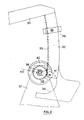
- the basic construction of the baler is conventional and only the top of the bale case or chamber 10 is shown in which a rectangular bale of crop material is formed and, when completed, is tied and eventually discharged from the machine.
- the tying operation is effected by securing means which may be in the form of conventional needles which enter the bale chamber 10 from below and carry twine with which the bale is wrapped; the twine being tied by one or more knotters (not shown), depending on how many strands of twine are employed across the bale.
- the knotters form part of the securing means.
- the bale chamber 10 has two opposed sides 11, a top 12 and can be provided with angled corner reinforcing members 13 extending longitudinally of the bale chamber 10.
- a shaft 15 is journalled in the brackets 14 and extends therebetween transversely of the bale chamber 10.
- the knotters are carried and operated by the shaft 15 and driven from the baler operating power source by an endless chain (not shown) via a sprocket (also not shown). The pitch of circle of this sprocket is indicated at 18.
- a one-revolution clutch 19 is mounted on the shaft 15 and drivingly connects this sprocket to the shaft 15 for one revolution each time the clutch 19 is actuated. This then drives the knotters through one complete tying cycle which is accomplished during a return stroke of the plunger (not shown) operating within the bale chamber 10.
- the clutch 19 has a stop pawl 20 which normally engages a detent 21 to hold the clutch 19 disengaged.
- the detent 21 is provided at one end of generally horizontal arm 24 of a bell crank lever which is pivoted at 25 to the associated bracket 14.
- the other arm 26 of the bell crank lever extends generally vertically and carries a cam follower 28 which is arranged to engage a cam surface (not shown) on the continuously rotating portion of the clutch 19.
- the upper end of the other arm 26 is connected to one end of a spring 29, the other end of which is attached to the associated bracket 14.
- the spring 29 operates to urge the bell crank lever 24, 26 in a counterclockwise direction as seen in Figure 1 about its pivot 25 so as to move the detent 21 downwardly out of engagement with the clutch stop pawl 20 and the cam follower 28 towards the cam surface for engagement therewith.
- a trip arm 30 which has a portion 31 pivotally attached at one end at 27 to the bell crank arm 26.
- a second portion 32 of the trip arm 30 is hooked with respect to the portion 31 and is in the form of a sector formed with teeth to provide a rack 33 on one edge.
- the outer end of the second trip arm portion 32 is formed with a trip notch or recess 34.
- the rack 33 normally engages a pinion 35 fixed to a shaft 36 journalled in a pair of spaced brackets 37 attached to the top wall 12 of the bale chamber 10.
- the shaft 36 extends across the bale chamber 10 and also has fixed thereto a toothed metering wheel 38 (usually referred to as a star wheel) which extends through the top wall 12 into the bale chamber 10 for engagement with the bales progressing therealong.
- a toothed metering wheel 38 (usually referred to as a star wheel) which extends through the top wall 12 into the bale chamber 10 for engagement with the bales progressing therealong.
- the operation of the metering means is based on rotation of the metering wheel 38 which is effected by the bales moving progressively along the bale chamber 10 as they are being formed and in as much as the wheel 38 engages the top of these bales during said movement.
- Rotation of the wheel 38 results in rotation of the shaft 36 and hence rotation of the pinion 35 which, because it is held stationary, drives the rack 33, and hence the trip arm 30, counterclockwise about the pivot 27.
- the movement of the rack 33 relative to the pinion 35 is guided by two discs 40 provided on either side of the pinion and engageable with respective sides of the trip arm portion 32.
- the clutch 19 is now operated and thus drives the shaft 15 and hence the knotters which tie the twine or the like with which the completed bale has been wrapped.
- the cam follower 28 is engaged by a rise in the cam surface (not shown) whereby the bell crank lever 24, 26 is pivoted clockwise and drives the trip arm 30 to the right so as to disengage the recess 34 from the pinion 35 and allow the trip arm 30 to drop back to its initial position of Figure 1 which is dictated by a movable stop 39 on the trip arm portion 32.
- the trip arm portion 32 is formed from a folded piece of sheet metal and the roller 41 is mounted therebetween on a pivot 42.
- roller 41 may be positioned such that the point on the periphery thereof engaged by the pinion 35, is below the outer extremities of the teeth of the rack 33, it also may be positioned so that this point is proud of the rack teeth, thus again ensuring that the drive connection between the rack 33 and pinion 35 is broken positively when the recess is at the point to engage with the pinion 35.
Landscapes
- Life Sciences & Earth Sciences (AREA)
- Environmental Sciences (AREA)
- Storage Of Harvested Produce (AREA)
Priority Applications (3)
| Application Number | Priority Date | Filing Date | Title |
|---|---|---|---|
| DE8686200302T DE3663321D1 (en) | 1986-02-27 | 1986-02-27 | Agricultural balers |
| EP86200302A EP0242448B1 (de) | 1986-02-27 | 1986-02-27 | Landwirtschaftliche Ballenpresse |
| US07/016,690 US4815372A (en) | 1986-02-27 | 1987-02-19 | Bale length control for agricultural balers |
Applications Claiming Priority (1)
| Application Number | Priority Date | Filing Date | Title |
|---|---|---|---|
| EP86200302A EP0242448B1 (de) | 1986-02-27 | 1986-02-27 | Landwirtschaftliche Ballenpresse |
Publications (2)
| Publication Number | Publication Date |
|---|---|
| EP0242448A1 true EP0242448A1 (de) | 1987-10-28 |
| EP0242448B1 EP0242448B1 (de) | 1989-05-17 |
Family
ID=8195705
Family Applications (1)
| Application Number | Title | Priority Date | Filing Date |
|---|---|---|---|
| EP86200302A Expired EP0242448B1 (de) | 1986-02-27 | 1986-02-27 | Landwirtschaftliche Ballenpresse |
Country Status (3)
| Country | Link |
|---|---|
| US (1) | US4815372A (de) |
| EP (1) | EP0242448B1 (de) |
| DE (1) | DE3663321D1 (de) |
Cited By (2)
| Publication number | Priority date | Publication date | Assignee | Title |
|---|---|---|---|---|
| WO1989003720A1 (en) * | 1987-10-23 | 1989-05-05 | Massachusetts Institute Of Technology | Methods and devices for gas cleaning |
| EP1042950A1 (de) * | 1999-04-03 | 2000-10-11 | Case Harvesting Systems GmbH | Grossballenpresse |
Families Citing this family (2)
| Publication number | Priority date | Publication date | Assignee | Title |
|---|---|---|---|---|
| US5482066A (en) * | 1994-01-11 | 1996-01-09 | Kemac, Inc. | Parts washing machine |
| US12376528B2 (en) | 2019-12-30 | 2025-08-05 | Agco Corporation | Square baler needle lockout device |
Citations (2)
| Publication number | Priority date | Publication date | Assignee | Title |
|---|---|---|---|---|
| US2911904A (en) * | 1955-06-21 | 1959-11-10 | Case Co J I | Automatic tying mechanism for balers |
| DE1920534A1 (de) * | 1968-06-21 | 1970-08-27 | Sperry Rand Corp | Klemmvorrichtung fuer Bindeschnur einer Verknotungseinheit fuer Ballenpressen |
Family Cites Families (6)
| Publication number | Priority date | Publication date | Assignee | Title |
|---|---|---|---|---|
| US75523A (en) * | 1868-03-17 | Daniel l | ||
| US664100A (en) * | 1894-01-17 | 1900-12-18 | Walter Scott | Bed-motion for cylinder printing-machines. |
| US2897748A (en) * | 1957-03-26 | 1959-08-04 | Sperry Rand Corp | Hay baler |
| US3221639A (en) * | 1964-10-23 | 1965-12-07 | Sperry Rand Corp | Bale length control device |
| US3862592A (en) * | 1973-04-30 | 1975-01-28 | Percy F Freeman | Bale forming and tying mechanism |
| US3931760A (en) * | 1975-03-03 | 1976-01-13 | Deere & Company | Bale length control mechanism |
-
1986
- 1986-02-27 DE DE8686200302T patent/DE3663321D1/de not_active Expired
- 1986-02-27 EP EP86200302A patent/EP0242448B1/de not_active Expired
-
1987
- 1987-02-19 US US07/016,690 patent/US4815372A/en not_active Expired - Lifetime
Patent Citations (2)
| Publication number | Priority date | Publication date | Assignee | Title |
|---|---|---|---|---|
| US2911904A (en) * | 1955-06-21 | 1959-11-10 | Case Co J I | Automatic tying mechanism for balers |
| DE1920534A1 (de) * | 1968-06-21 | 1970-08-27 | Sperry Rand Corp | Klemmvorrichtung fuer Bindeschnur einer Verknotungseinheit fuer Ballenpressen |
Cited By (2)
| Publication number | Priority date | Publication date | Assignee | Title |
|---|---|---|---|---|
| WO1989003720A1 (en) * | 1987-10-23 | 1989-05-05 | Massachusetts Institute Of Technology | Methods and devices for gas cleaning |
| EP1042950A1 (de) * | 1999-04-03 | 2000-10-11 | Case Harvesting Systems GmbH | Grossballenpresse |
Also Published As
| Publication number | Publication date |
|---|---|
| DE3663321D1 (en) | 1989-06-22 |
| EP0242448B1 (de) | 1989-05-17 |
| US4815372A (en) | 1989-03-28 |
Similar Documents
| Publication | Publication Date | Title |
|---|---|---|
| DE2748594C2 (de) | Ballenformvorrichtung | |
| DE19715280C2 (de) | Kolbenpresse zur Herstellung von Preßballen aus Erntegut | |
| US4557189A (en) | Apparatus for binding rolled bales of agricultural harvested crops | |
| US6161368A (en) | Baler for harvested crops | |
| US4117775A (en) | Tying needle safety control for crop balers | |
| ES2010487A4 (es) | Sistema de control para detectar mal funcionamiento de un mecanismo anulador en su embalador de cosecha | |
| EP0242448B1 (de) | Landwirtschaftliche Ballenpresse | |
| EP0883986B1 (de) | Sicherheitsvorrichtung für eine Nadelauslöseeinrichtung | |
| EP0426905B1 (de) | Vorrichtung zum Einrücken der Knotenkupplung | |
| US6644181B2 (en) | Binding device for a big baler | |
| US5156085A (en) | Knotter trip mechanism with cooperating clutch mechanism | |
| US2826985A (en) | Rotary baler | |
| US3221639A (en) | Bale length control device | |
| US4455930A (en) | Method and apparatus for delivering twine to a baler knotter | |
| EP0087432B1 (de) | Ballenpresse | |
| US3862592A (en) | Bale forming and tying mechanism | |
| US3419300A (en) | Twine finger for knotter mechanism of baler | |
| EP0158404B1 (de) | Kupplungsmechanismus für den Knüpfer | |
| US2701517A (en) | Metering and trigger mechanism for bale tiers | |
| US4493498A (en) | Knotter with an improved Geneva mechanism | |
| US2911904A (en) | Automatic tying mechanism for balers | |
| US3931760A (en) | Bale length control mechanism | |
| US2469578A (en) | Baler wire cutting and holding means | |
| EP0086205B1 (de) | Verfahren und vorrichtung, um dem knüpfapparat einer strohpresse den faden zuzuführen | |
| US2772628A (en) | Bale metering and tripping mechanism |
Legal Events
| Date | Code | Title | Description |
|---|---|---|---|
| PUAI | Public reference made under article 153(3) epc to a published international application that has entered the european phase |
Free format text: ORIGINAL CODE: 0009012 |
|
| 17P | Request for examination filed |
Effective date: 19860227 |
|
| AK | Designated contracting states |
Kind code of ref document: A1 Designated state(s): DE FR GB |
|
| RAP3 | Party data changed (applicant data changed or rights of an application transferred) |
Owner name: FORD NEW HOLLAND N.V. |
|
| 17Q | First examination report despatched |
Effective date: 19880909 |
|
| GRAA | (expected) grant |
Free format text: ORIGINAL CODE: 0009210 |
|
| AK | Designated contracting states |
Kind code of ref document: B1 Designated state(s): DE FR GB |
|
| REF | Corresponds to: |
Ref document number: 3663321 Country of ref document: DE Date of ref document: 19890622 |
|
| ET | Fr: translation filed | ||
| PLBE | No opposition filed within time limit |
Free format text: ORIGINAL CODE: 0009261 |
|
| STAA | Information on the status of an ep patent application or granted ep patent |
Free format text: STATUS: NO OPPOSITION FILED WITHIN TIME LIMIT |
|
| 26N | No opposition filed | ||
| REG | Reference to a national code |
Ref country code: GB Ref legal event code: IF02 |
|
| REG | Reference to a national code |
Ref country code: FR Ref legal event code: CD |
|
| PGFP | Annual fee paid to national office [announced via postgrant information from national office to epo] |
Ref country code: FR Payment date: 20041221 Year of fee payment: 20 |
|
| PGFP | Annual fee paid to national office [announced via postgrant information from national office to epo] |
Ref country code: GB Payment date: 20041222 Year of fee payment: 20 |
|
| PGFP | Annual fee paid to national office [announced via postgrant information from national office to epo] |
Ref country code: DE Payment date: 20041223 Year of fee payment: 20 |
|
| REG | Reference to a national code |
Ref country code: GB Ref legal event code: PE20 |
|
| PG25 | Lapsed in a contracting state [announced via postgrant information from national office to epo] |
Ref country code: GB Free format text: LAPSE BECAUSE OF EXPIRATION OF PROTECTION Effective date: 20060226 |