EP0242648A2 - Dispositif d'encrage pour une rotative d'impression planographique - Google Patents
Dispositif d'encrage pour une rotative d'impression planographique Download PDFInfo
- Publication number
- EP0242648A2 EP0242648A2 EP87104792A EP87104792A EP0242648A2 EP 0242648 A2 EP0242648 A2 EP 0242648A2 EP 87104792 A EP87104792 A EP 87104792A EP 87104792 A EP87104792 A EP 87104792A EP 0242648 A2 EP0242648 A2 EP 0242648A2
- Authority
- EP
- European Patent Office
- Prior art keywords
- roller
- inking unit
- stamp
- unit according
- holder
- Prior art date
- Legal status (The legal status is an assumption and is not a legal conclusion. Google has not performed a legal analysis and makes no representation as to the accuracy of the status listed.)
- Withdrawn
Links
Images
Classifications
-
- B—PERFORMING OPERATIONS; TRANSPORTING
- B41—PRINTING; LINING MACHINES; TYPEWRITERS; STAMPS
- B41F—PRINTING MACHINES OR PRESSES
- B41F31/00—Inking arrangements or devices
- B41F31/15—Devices for moving vibrator-rollers
-
- B—PERFORMING OPERATIONS; TRANSPORTING
- B41—PRINTING; LINING MACHINES; TYPEWRITERS; STAMPS
- B41F—PRINTING MACHINES OR PRESSES
- B41F31/00—Inking arrangements or devices
Definitions
- the invention relates to an inking unit for a rotary flat printing machine with an ink fountain roller, a plurality of transfer and friction rollers and at least one application roller, and a device for uniformizing the color relief on the application roller.
- Such an inking unit is known from DE-OS 20 52 806.
- a doctor blade from which the doctored ink is fed to a collecting container, is assigned to several friction rollers interacting with an application roller.
- Much more ink is supplied from the ink fountain than the plate needs for printing.
- a considerably thicker layer of ink than required is applied to the application roller. This ink layer is split on the downstream rubbing rollers. The ink removed from the application roller by the friction rollers is scraped off and returned to the collecting container.
- a disadvantage of this inking unit is, on the one hand, that the metering of the amount of ink actually required for printing cannot be carried out by the ink knife suitable for precise metering or the cycle times of the lifting roller on the ink fountain roller. Rather, this must be done by multiple color splitting between the applicator roller and the friction rollers.
- the ink splitting does not completely eliminate a relief present on the applicator roller, since the ink layer on the applicator roller splits into two equally strong sub-layers on each friction roller, so that in principle a relief is retained.
- the invention has for its object to develop an inking unit of the type mentioned in such a way that with precise meterability of those to be applied to the plate cylinder Any amount of color relief that occurs.
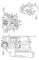
- the inking unit shown in FIG. 1 comprises an ink fountain 1 with an ink fountain roller 2 and an ink knife 3.
- a lifting roller 4 interacts with the ink fountain roller 3, which transfers the ink to a rubbing roller 5.
- the inking unit also has a number of transfer rollers 6, friction rollers 7 and applicator rollers 8, 9.
- the arrangement of the rollers of the inking unit is of no importance for the invention; for example, a differently designed lifter inking unit or a film inking unit could also be equipped according to the invention.
- the application rollers 8, 9 transfer the ink to a plate cylinder 10 rotating in the direction of arrow a.
- a stamp 11 can be set tangentially in the direction of arrow b to the application roller 9, which supplies ink to the plate cylinder as the last one of the application rollers 8, 9.
- the stamp 11 extends over the entire length of the application roller 9 and has a T-shaped cross section with a flat contact surface 12 facing the application roller 9.
- a carrier 14 is fastened at its two ends to a side wall 13 in which the rollers of the inking unit are mounted. Between two side parts 15 of the carrier 14, a holder 16 is mounted so as to be movable radially to the application roller 9. One end of a pressure spring 17, the other end of which rests on an abutment 18, is supported on the holder 16. The abutment 18 is screwed into a continuous thread of the carrier 14. By further screwing in or out the abutment 18, the force exerted by the pressure spring 17 on the holder 16 can be changed.
- the holder 16 has two side parts 19.
- a roller 20 is mounted on each of the two side parts 19.
- the two rollers 20 are thus under the action of the pressure spring 17 on the stamp 11 and press it against the applicator roller 9.
- the holder 16 carries two further rollers 21 indicated by dashed lines, which abut on both sides of the T-shaped middle piece of the holder 11 and thus its lateral Prevent displacement.
- a further roller 22 is mounted on the underside of the stamp 11, which engages in a curved groove guide 23 of a flange 24 fixedly connected to the applicator roller 9.
- On the holder 14 there are also a bottom part 25, which prevents the stamp 11 from falling out of the holder 15, and a front plate 26, which secures the holder 16 against displacements parallel to the axis of the application roller 9.
- the applicator roller 9 supplies the plate cylinder 10 with the most color, it is sufficient to assign the stamp to this roller. In principle, however, there is the possibility of also assigning a stamp 11 to further application rollers.
- the cam-groove guide 23 together with the roller 22 ensures a back and forth movement of the stamp 11 which runs parallel to the axis of the roller 9.
- this is not absolutely necessary, since in some cases it is the only one Pressure of the stamp 11 against an applicator roller 9 can produce a sufficiently uniform ink layer on this roller.
- the ink knife 3 and the ink fountain roller 2 can be adjusted very simply and precisely via the cycle times of the lifting roller 4 or in film inking units.
Landscapes
- Inking, Control Or Cleaning Of Printing Machines (AREA)
- Screen Printers (AREA)
Applications Claiming Priority (2)
| Application Number | Priority Date | Filing Date | Title |
|---|---|---|---|
| DE3613877 | 1986-04-24 | ||
| DE19863613877 DE3613877A1 (de) | 1986-04-24 | 1986-04-24 | Farbwerk fuer eine rotationsflachdruckmaschine |
Publications (2)
| Publication Number | Publication Date |
|---|---|
| EP0242648A2 true EP0242648A2 (fr) | 1987-10-28 |
| EP0242648A3 EP0242648A3 (fr) | 1989-04-26 |
Family
ID=6299439
Family Applications (1)
| Application Number | Title | Priority Date | Filing Date |
|---|---|---|---|
| EP87104792A Withdrawn EP0242648A3 (fr) | 1986-04-24 | 1987-04-01 | Dispositif d'encrage pour une rotative d'impression planographique |
Country Status (4)
| Country | Link |
|---|---|
| US (1) | US4753166A (fr) |
| EP (1) | EP0242648A3 (fr) |
| JP (1) | JPS62257850A (fr) |
| DE (1) | DE3613877A1 (fr) |
Families Citing this family (5)
| Publication number | Priority date | Publication date | Assignee | Title |
|---|---|---|---|---|
| US4796530A (en) * | 1987-06-01 | 1989-01-10 | Pathfinder Graphic Associates Inc. | Oscillating roll for printing presses |
| US5178678A (en) * | 1989-06-13 | 1993-01-12 | Dahlgren International, Inc. | Retractable coater assembly including a coating blanket cylinder |
| US4934305A (en) * | 1989-06-13 | 1990-06-19 | Dahlgren International, Inc. | Retractable coater assembly including a coating blanket cylinder |
| US5630363A (en) | 1995-08-14 | 1997-05-20 | Williamson Printing Corporation | Combined lithographic/flexographic printing apparatus and process |
| CN100575082C (zh) * | 2004-08-04 | 2009-12-30 | 海德堡印刷机械股份公司 | 印刷机 |
Family Cites Families (21)
| Publication number | Priority date | Publication date | Assignee | Title |
|---|---|---|---|---|
| DE238850C (fr) * | ||||
| DE346247C (de) * | 1920-04-23 | 1921-12-28 | Albert & Cie A G | Farbwerk fuer Druckmaschinen |
| GB256703A (en) * | 1925-05-14 | 1926-08-16 | Isaac Charles Squier | Improvements in inking mechanism for printing presses |
| US1942490A (en) * | 1932-09-23 | 1934-01-09 | Hugh T Quigley | Ink double-rolling control |
| US2076203A (en) * | 1934-12-21 | 1937-04-06 | Mailander Willy | Photogravure plate printing press |
| US2318504A (en) * | 1938-12-09 | 1943-05-04 | Frederick W Lodding | Doctor operating mechanism for rolls and cylinders |
| DE2052806A1 (de) * | 1970-10-28 | 1972-05-04 | Koenig & Bauer Schnellpressfab | Farbwerk fur Druckmaschinen |
| DE2243248A1 (de) * | 1972-09-02 | 1974-03-21 | Roland Offsetmaschf | Farbwerk an bogen verarbeitenden maschinen, insbesondere offsetmaschinen |
| DE2509837A1 (de) * | 1974-04-24 | 1975-11-06 | Xerox Corp | Verfahren zum farbtraenken einer oberflaeche |
| CH583097A5 (fr) * | 1975-05-05 | 1976-12-31 | Wifag Maschf | |
| US4126091A (en) * | 1976-12-21 | 1978-11-21 | Cohen Abraham N | Fountain blade and apparatus for calibrating the same |
| DE2658362C3 (de) * | 1976-12-23 | 1984-08-09 | Hinterkopf, Kurt G., Dipl.-Ing. (FH), 7332 Eislingen | Farbwerk für eine Druckmaschine, insbesondere zum Bedrucken von Tuben, Hülsen u.dgl. |
| US4151797A (en) * | 1977-05-04 | 1979-05-01 | Mid America Tag And Label Company, Inc. | Doctor blade apparatus |
| US4354449A (en) * | 1978-07-03 | 1982-10-19 | The Black Clawson Company | Two sided coater |
| DE2902230A1 (de) * | 1979-01-20 | 1980-07-24 | Maschf Augsburg Nuernberg Ag | Farbwerk |
| DE3028406C2 (de) * | 1980-07-26 | 1983-09-15 | Heidelberger Druckmaschinen Ag, 6900 Heidelberg | Vorrichtung zum axialen Hin- und Herbewegen von Reibwalzen im Farbwerk von Druckmaschinen |
| DD154530A5 (de) * | 1980-11-05 | 1982-03-31 | Dahlgren Mfg Co | Verfahren und vorrichtung zum dosieren von druckfarbe |
| US4398463A (en) * | 1981-08-19 | 1983-08-16 | Motter Printing Press Co. | Non-repeat doctor blade drive |
| DE3225378A1 (de) * | 1982-07-07 | 1984-01-12 | Koenig & Bauer AG, 8700 Würzburg | Farbwerk |
| DE3324893C1 (de) * | 1983-07-09 | 1985-03-14 | Heidelberger Druckmaschinen Ag, 6900 Heidelberg | Vorrichtung zum Dosieren der Farbe bei Offsetdruckmaschinen |
| DE3344778C1 (de) * | 1983-12-10 | 1985-04-11 | M.A.N.- Roland Druckmaschinen AG, 6050 Offenbach | Farbdosiervorrichtung für das Farbwerk einer Durckmaschine |
-
1986
- 1986-04-24 DE DE19863613877 patent/DE3613877A1/de active Granted
-
1987
- 1987-03-27 US US07/031,699 patent/US4753166A/en not_active Expired - Fee Related
- 1987-04-01 EP EP87104792A patent/EP0242648A3/fr not_active Withdrawn
- 1987-04-16 JP JP62092141A patent/JPS62257850A/ja active Pending
Also Published As
| Publication number | Publication date |
|---|---|
| EP0242648A3 (fr) | 1989-04-26 |
| DE3613877A1 (de) | 1987-10-29 |
| JPS62257850A (ja) | 1987-11-10 |
| US4753166A (en) | 1988-06-28 |
| DE3613877C2 (fr) | 1988-09-01 |
Similar Documents
| Publication | Publication Date | Title |
|---|---|---|
| CH620864A5 (fr) | ||
| EP0453910B1 (fr) | Chambre de racle | |
| CH672096A5 (fr) | ||
| DE1923475B2 (de) | Vorrichtung zur an- und abstellung der feuchtwalzen einer offset-rotationsdruckmaschine mit einem aus einer tauchwalze, einer zumesswalze, einer zwischenwalze und einer oder mehreren auftragswalzen bestehenden feuchtwerk, das eine schalteinrichtung, die ueber hebel bedienbar ist, aufweist | |
| EP0182156A2 (fr) | Machine d'impression offset | |
| EP0751256A2 (fr) | Ensemble de dosage | |
| EP0617168A1 (fr) | Dispositif de dosage pour l'enduction de bandes en mouvement, de préférence de papier ou de carton | |
| DE4213660C2 (de) | Kurzfarbwerk für eine Rollenrotationsdruckmaschine | |
| DE1243695B (de) | Farbwerk fuer Druckmaschinen | |
| DE102012201378A1 (de) | Vorrichtung und Verfahren zur Anstellung einer Rakel an eine Mantelfläche einer rotierbaren Walze | |
| EP0512267B1 (fr) | Laminoir | |
| DE3613877C2 (fr) | ||
| DE4400563C2 (de) | Walze in einem Farbwerk oder Feuchtwerk einer Rotationsdruckmaschine | |
| EP0210671B1 (fr) | Dispositif de mouillage pour machine à imprimer | |
| DE4004963A1 (de) | Vorrichtung zum auftragen von klebstoff auf zuschnitte von verpackungsmaterial | |
| DE4213663C2 (de) | Rakelbalken für ein Kurzfarbwerk einer Rollenrotationsdruckmaschine | |
| CH652347A5 (de) | Vorrichtung zum aufbringen eines fluessigen bzw. halbfluessigen mediums auf die druckplatte einer druckmaschine, insbesondere offsetdruckmaschine. | |
| DE3302872A1 (de) | Kurzfarbwerk | |
| EP0195378B1 (fr) | Dispositif d'impression | |
| EP0845354B1 (fr) | Bac à encre pour presses rotatives | |
| EP0741018A2 (fr) | Dispositif pour le placement d'un rouleau d'application | |
| DE3630491A1 (de) | Vorrichtung zum wahlweisen axialen bewegen von farbauftragwalzen | |
| DD148607A1 (de) | Farbwerk | |
| DE3336919C2 (de) | Vorrichtung zum zonenweisen Verstellen eines Farbmessers | |
| DE1915280B2 (de) | Vorrichtung zum Einstellen der Auftragwalze eines Farbwerks einer Druckmaschine |
Legal Events
| Date | Code | Title | Description |
|---|---|---|---|
| PUAI | Public reference made under article 153(3) epc to a published international application that has entered the european phase |
Free format text: ORIGINAL CODE: 0009012 |
|
| AK | Designated contracting states |
Kind code of ref document: A2 Designated state(s): CH DE FR IT LI SE |
|
| PUAL | Search report despatched |
Free format text: ORIGINAL CODE: 0009013 |
|
| AK | Designated contracting states |
Kind code of ref document: A3 Designated state(s): CH DE FR IT LI SE |
|
| 17P | Request for examination filed |
Effective date: 19890310 |
|
| STAA | Information on the status of an ep patent application or granted ep patent |
Free format text: STATUS: THE APPLICATION IS DEEMED TO BE WITHDRAWN |
|
| 18D | Application deemed to be withdrawn |
Effective date: 19901003 |
|
| RIN1 | Information on inventor provided before grant (corrected) |
Inventor name: FISCHER, HERMANN |