EP0242725A2 - Spektrophotometer für Fernablesung - Google Patents
Spektrophotometer für Fernablesung Download PDFInfo
- Publication number
- EP0242725A2 EP0242725A2 EP87105293A EP87105293A EP0242725A2 EP 0242725 A2 EP0242725 A2 EP 0242725A2 EP 87105293 A EP87105293 A EP 87105293A EP 87105293 A EP87105293 A EP 87105293A EP 0242725 A2 EP0242725 A2 EP 0242725A2
- Authority
- EP
- European Patent Office
- Prior art keywords
- illumination
- sample
- remote reading
- reading spectrophotometer
- optical
- Prior art date
- Legal status (The legal status is an assumption and is not a legal conclusion. Google has not performed a legal analysis and makes no representation as to the accuracy of the status listed.)
- Granted
Links
Images


Classifications
-
- G—PHYSICS
- G01—MEASURING; TESTING
- G01N—INVESTIGATING OR ANALYSING MATERIALS BY DETERMINING THEIR CHEMICAL OR PHYSICAL PROPERTIES
- G01N21/00—Investigating or analysing materials by the use of optical means, i.e. using sub-millimetre waves, infrared, visible or ultraviolet light
- G01N21/17—Systems in which incident light is modified in accordance with the properties of the material investigated
- G01N21/47—Scattering, i.e. diffuse reflection
- G01N21/4738—Diffuse reflection, e.g. also for testing fluids, fibrous materials
- G01N21/474—Details of optical heads therefor, e.g. using optical fibres
-
- G—PHYSICS
- G01—MEASURING; TESTING
- G01J—MEASUREMENT OF INTENSITY, VELOCITY, SPECTRAL CONTENT, POLARISATION, PHASE OR PULSE CHARACTERISTICS OF INFRARED, VISIBLE OR ULTRAVIOLET LIGHT; COLORIMETRY; RADIATION PYROMETRY
- G01J3/00—Spectrometry; Spectrophotometry; Monochromators; Measuring colours
- G01J3/02—Details
- G01J3/0205—Optical elements not provided otherwise, e.g. optical manifolds, diffusers, windows
- G01J3/0254—Spectrometers, other than colorimeters, making use of an integrating sphere
-
- G—PHYSICS
- G01—MEASURING; TESTING
- G01J—MEASUREMENT OF INTENSITY, VELOCITY, SPECTRAL CONTENT, POLARISATION, PHASE OR PULSE CHARACTERISTICS OF INFRARED, VISIBLE OR ULTRAVIOLET LIGHT; COLORIMETRY; RADIATION PYROMETRY
- G01J3/00—Spectrometry; Spectrophotometry; Monochromators; Measuring colours
- G01J3/28—Investigating the spectrum
- G01J2003/2866—Markers; Calibrating of scan
-
- G—PHYSICS
- G01—MEASURING; TESTING
- G01J—MEASUREMENT OF INTENSITY, VELOCITY, SPECTRAL CONTENT, POLARISATION, PHASE OR PULSE CHARACTERISTICS OF INFRARED, VISIBLE OR ULTRAVIOLET LIGHT; COLORIMETRY; RADIATION PYROMETRY
- G01J3/00—Spectrometry; Spectrophotometry; Monochromators; Measuring colours
- G01J3/28—Investigating the spectrum
- G01J3/42—Absorption spectrometry; Double beam spectrometry; Flicker spectrometry; Reflection spectrometry
- G01J2003/425—Reflectance
-
- G—PHYSICS
- G01—MEASURING; TESTING
- G01J—MEASUREMENT OF INTENSITY, VELOCITY, SPECTRAL CONTENT, POLARISATION, PHASE OR PULSE CHARACTERISTICS OF INFRARED, VISIBLE OR ULTRAVIOLET LIGHT; COLORIMETRY; RADIATION PYROMETRY
- G01J3/00—Spectrometry; Spectrophotometry; Monochromators; Measuring colours
- G01J3/28—Investigating the spectrum
- G01J3/30—Measuring the intensity of spectral lines directly on the spectrum itself
- G01J3/36—Investigating two or more bands of a spectrum by separate detectors
-
- G—PHYSICS
- G01—MEASURING; TESTING
- G01N—INVESTIGATING OR ANALYSING MATERIALS BY DETERMINING THEIR CHEMICAL OR PHYSICAL PROPERTIES
- G01N21/00—Investigating or analysing materials by the use of optical means, i.e. using sub-millimetre waves, infrared, visible or ultraviolet light
- G01N21/17—Systems in which incident light is modified in accordance with the properties of the material investigated
- G01N2021/1793—Remote sensing
-
- G—PHYSICS
- G01—MEASURING; TESTING
- G01N—INVESTIGATING OR ANALYSING MATERIALS BY DETERMINING THEIR CHEMICAL OR PHYSICAL PROPERTIES
- G01N2201/00—Features of devices classified in G01N21/00
- G01N2201/06—Illumination; Optics
- G01N2201/065—Integrating spheres
-
- G—PHYSICS
- G01—MEASURING; TESTING
- G01N—INVESTIGATING OR ANALYSING MATERIALS BY DETERMINING THEIR CHEMICAL OR PHYSICAL PROPERTIES
- G01N2201/00—Features of devices classified in G01N21/00
- G01N2201/06—Illumination; Optics
- G01N2201/069—Supply of sources
- G01N2201/0696—Pulsed
-
- G—PHYSICS
- G01—MEASURING; TESTING
- G01N—INVESTIGATING OR ANALYSING MATERIALS BY DETERMINING THEIR CHEMICAL OR PHYSICAL PROPERTIES
- G01N2201/00—Features of devices classified in G01N21/00
- G01N2201/08—Optical fibres; light guides
- G01N2201/0806—Light rod
-
- G—PHYSICS
- G01—MEASURING; TESTING
- G01N—INVESTIGATING OR ANALYSING MATERIALS BY DETERMINING THEIR CHEMICAL OR PHYSICAL PROPERTIES
- G01N2201/00—Features of devices classified in G01N21/00
- G01N2201/12—Circuits of general importance; Signal processing
- G01N2201/126—Microprocessor processing
Definitions
- This invention relates to a remote reading spectrophotometer for conveniently and accurately measuring the spectral characteristics of a sample at relatively long distances.
- Spectrophotometers are widely used in many settings to determine spectral reflectance.
- spectrophotometers are used to determine whether goods in production are of consistently acceptable appearance.
- the object is to ensure that the spectral reflectance of the production material is consistent throughout its length and width so that the ultimate goods will be of the highest possible quality.
- textile manufacturers use spectrophotometers during continuous prodcution to monitor the consistency and effectiveness of their dying processes. Ideally, the textile manufacturers would place a spectrophotometer on every final inspection rack to ensure consistent quality of each roll of material at the final production stage prior to shipping.
- limitations of prior spectrophotometers make it impractical to mount a spectrophotometer on every inspection rack.
- Prior spectrophotometers positioned close to the sample surface simply cannot accurately measure some surfaces.
- Prior spectrophotometers include an illumination source which emits light in many directions from a point source and a detector which receives and detects the light reflected from the surface being measured. This arrangement provides an adequate measurement for most continuous flat surfaces when the light source and detector are placed close to the sample, but it is unreliable when surfaces having a relief profile are spatially scanned.
- the manufacture of sculptured carpets is one application where accurate spectral measurements would be desirable but have, heretobefore, been unattainable.
- the said carpets have an uneven surface and a traditional spectrophotometer placed close to such a carpet will not give accurate spectral reflectance measurements since each area of the sculptured carpet reflects light in different directions at varying intensities. Consequently, the light reflected to the detector differs widely from area to area as a result of the carpet contour and a scan of this surface with a traditional spectrophotometer will yield erratic and unrealiable results.
- a remote reading spectrophotometer which comprises illumination means; first optical means for directing illumination from said illumination means to an area of a sample to be measured; means for obtaining an illumination beam from said first optical means; second optical means for sequentially focusing component wavelengths of said illumination reflected from said sample onto a monochromator or polychromator; and analyzing means for analyzing said reflected illumination and said reference beam to determine the spectral characteristics of said sample.
- a high intensity illumination source preferably a pulsed Xenon lamp
- An illumination focusing lens focuses a magni fied image of the source or, alternatively, projects a collimated beam from the source onto an area of the sample to be measured.
- One end of at least one reference fiber optic member is positioned in the path of the illumination to obtain a reference beam for comparison purposes. The other end of the fiber optic member is butted against a bandpass filter adjacent to a reference detector.
- a sample imaging lens is aligned to view a portion of the illuminated sample area and focuses the image onto a polychromator positioned so that the light reflected from the sample is separated into its component wavelengths for separate detection by an array of detectors.
- the detected sample illumination and reference beams are amplified and converted into digital signals for processing by a microprocessor.
- the microprocessor determines the spectral reflectance of the sample using the reference beam information as a basis for determining the characteristics of the sample illumination.
- the reflected sample illumination is averaged over a relatively large sample area.
- a Kohler type illumination optics system similar to the illumination systems used in film projectors is provided.
- the illumination from the preferred pulsed Xenon lamp is incident upon a condenser lens and passes through an aperture to an objective lens.
- the objective lens focuses an image of the aperture onto an area of the sample to provide uniform sample illumination.
- a beamsplitter is placed between the condenser lens and the objective lens to obtain an illumination reference beam.
- the reference beam is focused onto the distant wall of an integrating sphere coated on its inner surface with a uniform white coating to produce an integrated diffuse reference source.
- the optical path from the illuminated area of the sample to the sample imaging lens passes through or alongside the integrating sphere.
- a beamswitch is provided which sequentially directs the integrated reference beam, as imaged on the inner surface of the integrated sphere, and the reflected sample image onto the polychromator during two sequential flashes of the preferred pulsed Xenon lamp.
- One or more discrete wavelength detectors preferably consisting of an optical fiber connected to a bandpass filter and a reference detector, are associated with the integrating sphere to monitor the spectral characteristics of the illumination source during both the reference and sample flashes.
- the microprocessor normalizes the illumination source between the two flashes utilizing the information obtained from the discrete wavelength detectors and then compares the sample and reference measurements on the basis of the normalized illumination. From this comparison the spectral reflectance characteristics of the sample are determined.
- the illumination and sample fields of view overlap to provide a relatively long depth of view once the system is aligned. Since the sample illumination is very uniform, this system is able to provide accurate spectral reflectance measurements over a long depth of field without realignment or recalibration. By sampling a relatively large, uniformly illuminated surface area the present invention provides accurate spectral reflectance measurements which are less dependent upon surface vibrations than prior spectrophotometers.
- a second polychromator is provided to receive and comprehensively analyze the spectral characteristics from the discrete wavelength detectors.
- the reference beam is focused directly onto a second polychromator without any integrating sphere.
- the reference beam is projected onto a diffuser by a conjugate objective lens and the beamswitch alternately directs the diffuse reference illumination from the diffuser or the reflected sample image to the polychromator.
- the discrete wavelength detectors for providing a normalization reference preferably constitute fibers disposed in the path of the diffuse illumination.
- a spectrophotometer which remarkably permits the spectral reflectance of the sample to be measured at a relatively great distance to the sample.
- this permits the spectrophotometer according to the invention to be mounted away from the sample without any need for expensive bridge mounting.
- the ability of the spectrophotometer of this invention to measure spectral reflectance at a distance to the sample allows the spectrophotometer to be removed from the immediate industrial processing environment of the sample, as by placing the spectrophotometer behind a clear glass barrier away from the production line.
- the spectrophotometer is able to accurately average the measurement of a uniformly illuminated sample area to advantageously reduce inaccuracies which might otherwise result from measuring a localized area of an irregularly contoured surface.
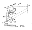
- a spectrophotometer generally shown as 10, is provided having an illumination source 12, a first optical means 14 consisting of one or more lenses, reference beam means 16 to carry a reference beam to one or more reference detectors 18, a second, reflected light optical means 20 to focus the illumination reflected from a sample A onto a polychromator 22 which separates and detects the intensity of the reflected sample illumination at numerous wavelengths, amplifying and integrating circuitry 46, and a microprocessor 40 to receive and process the data generated by the polychromator 22 and reference detectors 18 for further use in data display and/or system control.
- illumination source 12 preferably a high intensity pulsed Xenon lamp or continuous Xenon arc lamp, projects light to a focusing lens 24.
- a curved polished reflector 26 may be disposed behind the lamp 12 to ensure that as much light as possible is directed toward focusing lens 24 and to minimize the effects of beam drift or arc wander.
- polished reflector 26 is a spherical mirror with a magnification factor of -1.
- Focusing lens 24 projects the illumination from light source 12 toward the sample A so as to illuminate a portion thereof.
- Focusing lens 24 may either focus the illumination onto sample A as a magnified image of the lamp 12 or project the light in a collimated beam, as shown in Fig. 1, to create a defocused spot on the sample. In either case, an area of the sample is illuminated.
- One or more fiber optic pick-ups 28 are disposed in the path of the sample illumination to provide a reference beam of the illumination projected toward sample A.
- the reference beams from fiber optic elements 28 are filtered through bandpass filters 29 and are incident upon reference beam detectors 18, as by butting the end of each optical fiber against the filter and detector pair.
- the filters 29 might have a bandwidth on the order of 30 nm so that reference measurements at roughly two selected wavelengths are obtained.
- the reference beam may be obtained using traditional optical elements, such as a beamsplitter and a focusing lens.
- Sample A responds to the incident light by reflecting and absorbing different amounts of light at each wavelength to define the spectral "fingerprint" of the sample.
- a second optical arrangement 20, shown in Fig. 1 as a reflected light focusing lens 30, is provided to receive light reflected from a portion of the illuminated area of sample A and focus that reflected light onto a polychromator 22, where the reflected light is broken down into its component wavelengths for detection.
- Polychromator 22 includes a narrow slit 23 placed at the focal point of lens 30, a collimating lens 34, a dispersive element 36 such as a diffraction grating or a prism which receives the collimated beam from collimating lens 34 and separates the beam into its component wavelengths, and a focusing lens 38 which focuses the separated light from the dispersive element 36 onto a detector array 32.
- Detector array 32 includes detectors positioned to receive incident light corresponding to each wavelength region, thereby providing a multiple channel detection system. For convenience, detector array 32 is shown as an array of ten detectors to provide a ten channel system.
- Processing circuitry 46 receives the signals from each detector of array 32 for processing in an appropriate manner. This processing may involve amplification and integration of the signals for transmission to microprocessor 40. Needless to say, an analog-to-digital converter must be included, preferably within the microprocessor 40, in order for the microprocessor to receive and understand the amplified analog detector signals.
- FIG 3 shows an alternative arrangement for polychromator 22.
- fiber optic members 28 are led directly into the polychromator where dedicated filters 29 and reference detectors 18 are provided. It is contemplated that reference detectors 18 may simply be an extension of detector array 32.
- the polychromator arrangements described above and shown in Figs. 2 and 3 are preferred, other polychromator arrangements may be suitable and, indeed, even a monochromator arrangement may be used.
- the individual wavelengths of the reflected sample illumination to be measured may be sequentially directed to a single detector by adjusting the color separation device.
- the single detector signal would then be relayed to the amplifying and microprocessing circuitry.
- the analog-to-digital converter is included within the microprocessor 40, which receives and stores the data from the reference detectors and the sample detector array 32.
- the reference detector data is used to normalize the sample illumination to account for any shifts which may have occurred since the instrument was calibrated,and the sample measurement is then processed to calculate the spectral characteristics of the sample.
- the microprocessor may then provide a display of sample's spectral characteristics, i.e., the degree of reflectance of the sample at each measured wavelength, and/or automatically make process control adjustments based upon the sample measurements.
- the preferred illumination source is a high intensity pulsed Xenon lamp.
- Use of this readily available source with the dual beam measuring technique of this invention advantageously permits ambient room light to be ignored.
- heretofore unknown accuracy is obtained since the characteristics of the incident as well as reflected illumination are measured by the present invention. Consequently, the spectrophotometer according to the invention can be used in room light at relatively long distances without any interference from ambient light. Indeed, the invention permits accurate spectral reflectance measurement at distances on the order of 122 cm to 610 cm.
- sources than the preferred high intensity pulsed Xenon lamp may be used as, for example, a high intensity pulsed Krypton lamp or other pulsed noble gas lamp. It is also believed that a continuous source such as an arc lamp which provides high intensity illumination or a light source modulated to frequencies above room light could be used.
- Fig. 1 The optical configuration shown in Fig. 1 and described above has been found acceptable for numerous applications and may be applied with success, but certain limitations of that particular configuration have led to improvements which permit even greater accuracy and reliability in spectral measurements at long distances.
- the preferred Xenon illumination may vary over a small area of the illuminated spot depending upon the location of the lamp's "hot spots" in the image. Since lamp sources and, more particularly, the preferred Xenon lamp, often suffer from single beam drift or arc wander, the illumination at the sample can vary even without adjustment of the optics or movement of the sample. The effects of variations in the illumination at the relatively small reference beam pick-ups 28 disposed in the illumination path can be even more pronounced.
- the curved mirror 26 disposed behind light source 12 helps reducing the effects of beam drift and arc wander, but complete uniformity is not achieved with this improvement alone.
- Fig. 1 the structure shown in Fig. 1 must be refocused and the non-uniform light source must be recalibrated if the sample distance changes. Since the illumination at the sample is not very uniform, the working range is limited to a relatively shallow depth of focus surrounding the actual focal point.
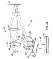
- Fig. 4 a second preferred embodiment of the invention including a Kohler type optical arrangement to assure uniform illumination at the sample is shown.
- the preferred pulsed Xenon light source 12 is provided with a curved reflector 26 to maximize the illumination directed to a first illumination lens 48 and reduce the effects of beam drift.
- Aperture defining means 51 such as a plate, are provided adjacent to first lens 48 to define a distinct illumination aperture.
- Lens 48 is preferably a condenser lens aligned to focus the illumination from light source 12 onto an objective lens 50, which focuses an image of the aperture onto the sample A resulting in a highly uniform illumination at the sample A.
- objective lens 50 compensates for any slight variations in light source 12 so that the illuminated area of sample A remains steady.
- the illumination optics of the second preferred embodiment provides a uniformly illuminated spot on the sample A. This facilitates proper alignment of the illumination and detection optics to assure an overlapping field of view and, consequently, accurate detection of the reflected illumination.
- the reference beam is obtained by providing a beamsplitter 52 between first and second lens elements 48 and 50, respectively.
- Beamsplitter 52 reflects a portion of the sample illumination from first lens 48 to an integrating sphere 54 through a first integrating sphere aperture 56.
- the reference beam is focused at a point on the far wall of the integrating sphere 54 from opening 56,and the inner walls of the integrating sphere 54 are coated with a uniform white coating so that the entire sphere becomes illuminated with a diffuse image of the reference beam.
- Integrating sphere 54 is also provided with second and third integrating sphere apertures 58 and 60, respectively.
- the reflected sample beam from a portion of the illuminated area of sample A passes through integrating sphere 54 along the chord defined by apertures 58 and 60 to sample focusing lens 30, which focuses the beam onto polychromator 22.
- the sample beam is detected by detector array 32 (not shown), processed by amplifying and integrating circuitry 46, and sent to microprocessor 40 so that the information can be translated into useful numerical data corresponding to the spectral reflectance characteristics of sample A.
- a beamswitch 64 is provided adjacent to third integrating sphere aperture 60.
- the beamswitch 64 permits unobstructed viewing of the sample beam by focusing lens 30, and in another position a reference beam from a portion of the white wall of integrating sphere 54 is directed to focusing lens 30 to the exclusion of the reflected sample image.
- beamswitch 64 which may, for example, be a pivoting prism, permits either the integrated reference beam or the sample beam to be selectively viewed by sample focusing lens 30 and, consequently, polychromator 22.
- the preferred pulsed Xenon lamp is used as illumination source 12
- two sequential pulsed flashes are provided.
- beamswitch 64 directs the sample beam to focusing lens 30 to be detected by polychromator 22.
- the spectral information from the sample is detected during this flash and is stored by microprocessor 40.
- beamswitch 64 alters the line of sight of focusing lens 30 to a portion of the inside wall of integrating sphere 54 so that the integrated reference beam is focused onto polychromator 22.
- the spectral information from the reference flash is also stored by microprocessor 40.
- microprocessor 40 has stored in it the full spectral characteristics of both the reference beam and the sample beam. Consequently, the date obtained from the sample beam can be analyzed relative to the reference beam data to determine the spectral characteristics of the sample A.
- two fiber optic pick-ups 128 are preferably led from integrating sphere 54 directly into polychromator 22, where they connect to bandpass filters 29 and dedicated reference detectors 18 (see Fig.3). It has been found that this type of measurement during both flashes at just two wavelengths, such as approximately 440 and 620 nanometers, can be correlated to give a reliable indication of shifts or failures in the illumination source. For more demanding applications, the measurements at these select wavelengths can be correlated to indicate changes at other wavelengths so that the reference and sample flashes can be mormalized to provide a more accurate comparison of the reference beam and sample image measurements.
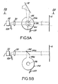
- Figs. 5A and 5B show the reference beam from beamsplitter 52 reflected into integrating sphere 154 through aperture 156. In this arrangement, the sample beam passes alongside the integrating sphere adjacent to the reference aperture 156a.
- Figure 5B taken along line 5B-5B of Fig.
- beamswitch 164 alternates between the position shown wherein the reference beam from integrating sphere 154 is directed to focusing lens 30, and position 164a, shown in phantom, out of the path of the sample beam, such that the sample beam is directed to focusing lens 30 to the exclusion of the reference beam. Consequently, polychromator 22 alternately receives and detects light from the reference and sample beams.
- fiber optic pick-ups 128 provide a partial reference at select wavelengths during both flashes.
- the integrating sphere might be replaced by another suitable optical arrangement which provides a uniform averaging of the reference beam.
- Fig. 5C One such arrangement is shown in Fig. 5C.
- the reference beam from beamsplitter 52 is focused by a conjugate objective lens 150 similar to the sample illumination objective lens 50 onto a diffuser 70.
- Beamswitch 164 selectively directs either the sample beam (position 164a) or the diffuse reference beam (position 164) to focusing lens 30 and polychromator 22.
- fiber optic pick-ups 228 would be placed in the path of the reference beam illumination from diffuser 70 in a manner similar to the placement of optical fiber pick-ups 28 in the first preferred embodiment shown in Fig. 1.
- optical fibers 228 are not subject to the illumination variations experienced by fibers 28 since fibers 228 are disposed in the path of uniform diffuse illumination rather than the image of the lamp source 12 as in the first preferred embodiment.
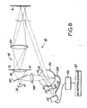
- a fiber optic pick-up 128 of the second preferred embodiment could be connected to a second polychromator 122, as shown in Fig. 6, in order to monitor the full reference beam over all pertinent wavelengths during both the reference and sample beam flashes.
- both polychromators could be connected to similar analyzing circuitry. This particular arrangement is desirable since a complete evaluation of the illumination source 12 at all pertinent wavelengths would be obtained during both the reference and sample flashes. Thus, any shift in the illumination source 12 would be known from second polychromator 122 and could be used to correlate the reference and sample beams to give a very accurate indication of the spectral reflectance of the sample.
- reference and sample beams could be measured simultaneously by two polychromators during a single flash of the preferred pulsed Xenon lamp.
- the reference beam is reflected from beamsplitter 52 to a focusing lens 150 and is focused onto second polychromator 122 in order to simulate the sample illumination.
- the data from both polychromators, 22 and 122 could be processed by similar amplifying and integrating circuitry 46 and microprocessor 40.
- the disadvantage of the configuration shown in Fig. 7 is that the first and second polychromators 22, 122 should be accurately calibrated relative to one another so that differences between the detection characteristics of the polychromators do not skew the evaluation of the sample reflectance.
- FIG. 8 A further alternativeconfiguration of the second preferred embodiment of the invention is shown in Fig. 8.
- the reference beam is obtained by placing a beamsplitter 152 between light source 12 and first lens element 48.
- Beamsplitter 152 reflects some of the illumination from lamp 12 to a conjugate lens element 148 which focuses the illumination onto the far wall of integrating sphere 54 through aperture 56.
- the sample beam passes through the integrating sphere 54 through second and third apertures 58, 60 and is focused onto polychromator 22 by focusing lens 30.
- beamswitch 64 permits both the sample and reference beams to be measured and integrating sphere optical pick-ups 128 permit the illumination from both flashes to be monitored at select wavelengths.
- the conjugate reference beam optical configuration shown in Fig. 8 could be combined with a dual polychromator system (Fig. 7) or with a diffuser type system (Fig. 5C) rather than an integrating sphere.
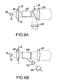
- the first illumination optical arrangement 14 may include an integrating rod such as a fiber optic bundle.
- Figs. 9A and 9B Such arrangements are shown in Figs. 9A and 9B.
- Fig. 9A an illumination system according to the invention including an integrating rod 68 is shown.
- the integrating rod 68 ensures that the illumination from first lens element 48 is accurately projected onto second lens element 50 to further assure uniform sample illumination.
- Beamsplitter 52 is positioned between integrating rod 68 and second lens element 50, as shown, to project the reference beam onto a conjugate second lens element 150 in a manner similar to the embodiment shown in Fig. 8.
- Lens element 50 could, of course, focus an image of the end of integrating rod 68 onto the sample or a Kohler optical arrangement could be provided in place of lens element 50 for even greater uniformity.
- FIG. 9B An alternative illumination optics arrangement including an integrating rod 168 is shown in Fig. 9B.
- Integrating rod 168 could be split to provide the sample and reference beams so that the illumination from lamp 12 enters integrating rod 168 from first lens element 48 and is split to provide both appropriate illumination of second lens element 50 and the reference beam.
- the reference beam from integrating rod 168 can, for example, be imaged through a conjugate objective lens 150 onto a second polychromator 122 in similar manner as described in connection with Fig. 7.
- the reference branch of the split integrating rod 168 could be coupled with other reference beam illumination systems shown herein. It is readily apparent that this arrangement is particularly suited to fiber optics technology.
- the second preferred embodiment of the invention provides remarkably uniform illumination at the sample which is, for the most part, independent of the spectrophotometer to sample distance.
- the illumination and measurement fields of view overlap for a relatively great distance to provide a very long depth of field.
- the measurement field of view fully overlaps the projected illumination at positions B and C as well.
- the present system in accordance with the second preferred embodiment is aligned for a sample distance of, approximately, 275 cm, the depth of view of the system is from, appr., 122 cm to infinity.
- the measurement variations experienced with the first preferred embodiment of the invention due to the various locations of lamp source "hot spots" in the illuminated area are minimized.
- averaging over a portion of the illuminated area of the sample surface can be achieved with the result that the only distance limitation on the system according to the second preferred embodiment is the brightness level of the illumination source.
- the relatively large sample area viewed by the system according to the second preferred embodiment provides more accurate measurement of the spectral reflectance of the sample since the measurement constitutes an integration over the entire area within the sample field of view. Since sample surfaces actually vary from one area to another, this averaging effect contributes to the outstanding accuracy of the present system compared to prior close measurement spectrophotometers. Indeed, the localized measurement used by prior spectrophotometers is partially responsible for the inability of traditional spectrophotometers to penetrate the market for measuring relief surfaces such as sculptured carpets. With prior spectrophotometers, the contour variations in such carpets result in dramatic changes in the relative distance from the illumination and pick-up members to the sample. This causes wide detection variations.
- the invention permits the spectral characteristics of irregular surfaces to be accurately measured from a distance by taking an overview of a relatively large sample area and averaging the results to accurately determine spectral response. Consequently, any variation in the relative distance from the illumination and detection members to the sample is minimal and any resulting measurement variations are inconsequential.
- the invention advantageously combines the ability to measure spectral reflectance characteristics at a relatively long distance with a long depth of focus and large sample area averaging.
- This unique combination of features permits the spectrophotometer of the invention to be mounted away from the sample surface. Accordingly, the spectrophotometer of the invention is inexpensive to install compared to prior spectrophotometers since the need for expensive custom designed bridge mountings is eliminated. Indeed, by providing spectral measurement from a distance to the sample, spectrophotometers of the invention can be used in applications where prior art spectrophotometers cannot even be considered.
- the unique features of the invention are particularly adapted for providing an inexpensive angular scanning system since the illumination and detection optical paths subtend a narrow angle. As a result, the respective optical apertures can be placed closely adjacent to one another.
- the spectrophotometer according to the second preferred embodiment can be arranged in a scanning configuration by providing a scanning mirror 76 pivotally mounted at center point 78.
- scanning mirror 76 is driven in a "flyback" or “sawtooth” pattern to accomplish an angular scan across sample A.
- the illumination beam is reflected to sample A and the corresponding reflected sample beam remains within the measurement field of view.
- a raster scan could be provided either by pivoting scanning mirror 76 in two directions or by providing a second scanning mirror in a known manner.
- FIG. 12 A commercial application of the scanning spectrophotometer of Fig. 11 is shown in Fig. 12.
- Scanning spectrophotometer 10 is mounted high above the continuous production sheet material and performs an angular scan across the entire width of the continuous sheet during the pivoting movement of scanning mirror 76 (see Fig. 11).
- a calibrated measurement standard can be placed adjacent to the production sheet so that the standard is regularly included in the scanning sweep of spectrophotometer 10.
- the spectrophotometer of the invention is mounted at a fixed location away from the sample to be measured.
- the illumination and measurement optics are aligned at an appropriate median sample distance and a known calibration standard is placed at the sample location.
- the spectrophotometer is then calibrated based on this standard and may thereafter be used to measure the spectral reflectance of a sample.
- the scanning spectrophotometer calibration standards corresponding to various points of scan, e.g., left, right and center, be provided to calibrate the scanning spectrophotometer to compensate for any angular color variations introduced by the different scan angles.
- the spectrophotometer should periodically be recalibrated using the known standard to ensure accuracy.
Landscapes
- Physics & Mathematics (AREA)
- Spectroscopy & Molecular Physics (AREA)
- General Physics & Mathematics (AREA)
- General Health & Medical Sciences (AREA)
- Analytical Chemistry (AREA)
- Biochemistry (AREA)
- Chemical & Material Sciences (AREA)
- Life Sciences & Earth Sciences (AREA)
- Immunology (AREA)
- Pathology (AREA)
- Health & Medical Sciences (AREA)
- Investigating Or Analysing Materials By Optical Means (AREA)
- Spectrometry And Color Measurement (AREA)
Applications Claiming Priority (3)
| Application Number | Priority Date | Filing Date | Title |
|---|---|---|---|
| US855168 | 1986-04-23 | ||
| US06/855,168 US4770530A (en) | 1986-04-23 | 1986-04-23 | Remote spectrophotometer |
| CA000538433A CA1319531C (en) | 1986-04-23 | 1987-05-29 | Remote spectrophotometer |
Publications (3)
| Publication Number | Publication Date |
|---|---|
| EP0242725A2 true EP0242725A2 (de) | 1987-10-28 |
| EP0242725A3 EP0242725A3 (en) | 1989-10-11 |
| EP0242725B1 EP0242725B1 (de) | 1994-01-05 |
Family
ID=25671364
Family Applications (1)
| Application Number | Title | Priority Date | Filing Date |
|---|---|---|---|
| EP87105293A Expired - Lifetime EP0242725B1 (de) | 1986-04-23 | 1987-04-09 | Spektrophotometer für Fernablesung |
Country Status (5)
| Country | Link |
|---|---|
| US (1) | US4770530A (de) |
| EP (1) | EP0242725B1 (de) |
| CA (1) | CA1319531C (de) |
| DE (2) | DE3788670T2 (de) |
| GB (1) | GB2189623B (de) |
Cited By (9)
| Publication number | Priority date | Publication date | Assignee | Title |
|---|---|---|---|---|
| EP0331629A1 (de) * | 1988-02-02 | 1989-09-06 | GRETAG Aktiengesellschaft | Handgerät zur Erfassung der optischen Remissionseigenschaften |
| US4929084A (en) * | 1988-02-02 | 1990-05-29 | Gretag Aktiengesellschaft | Measuring head |
| US4968140A (en) * | 1988-02-02 | 1990-11-06 | Gretag Aktiengesellschaft | Manual device for the determination or measurement of photometric data using a measuring head |
| WO1996024046A1 (de) * | 1995-02-04 | 1996-08-08 | Honeywell Ag | Vorrichtung zur farbmessung |
| DE19528855A1 (de) * | 1995-08-05 | 1997-02-06 | Leybold Ag | Verfahren und Vorrichtung zur spektralen Remissions- und Transmissionsmessung |
| WO1998012541A1 (en) * | 1996-09-16 | 1998-03-26 | Varian Australia Pty. Ltd. | Improved spectrophotometer |
| WO2000033039A1 (en) * | 1998-12-03 | 2000-06-08 | Varian Australia Pty. Ltd. | Uv-vis spectrophotometry |
| AU730982B2 (en) * | 1996-09-16 | 2001-03-22 | Agilent Technologies Australia (M) Pty Ltd | Improved spectrophotometer |
| EP3136084A1 (de) * | 2015-08-28 | 2017-03-01 | Samsung Electronics Co., Ltd. | Optischer sensor und verfahren zum betrieb des optischen sensors |
Families Citing this family (28)
| Publication number | Priority date | Publication date | Assignee | Title |
|---|---|---|---|---|
| US4888484A (en) * | 1986-02-20 | 1989-12-19 | Automatik Machinery Corporation | Apparatus and method for spectrophotometric analysis of a material in a moving process stream |
| DE3701721A1 (de) * | 1987-01-22 | 1988-08-04 | Zeiss Carl Fa | Remissionsmessgeraet zur beruehrungslosen messung |
| EP0371643A3 (de) * | 1988-11-23 | 1991-05-29 | W.R. Grace & Co.-Conn. | Verfahren und Vorrichtung zum Nachprüfen von Werkstücken |
| US5055684A (en) * | 1989-12-06 | 1991-10-08 | Nirsystems Incorporated | System to reduce wave shift error in spectrophotometer caused by hot spots in the light source |
| DE4005878A1 (de) * | 1990-02-24 | 1991-08-29 | Bruker Analytische Messtechnik | Raman-spektrometer |
| US5088821A (en) * | 1990-06-29 | 1992-02-18 | Nicolas J. Harrick | Spectroscopic analysis system with remote terminals |
| US6597457B1 (en) * | 1991-12-09 | 2003-07-22 | Goodrich Corporation | Calibration of solar reflectance panel |
| US5747813A (en) * | 1992-06-16 | 1998-05-05 | Kla-Tencop. Corporation | Broadband microspectro-reflectometer |
| DE4224299C2 (de) * | 1992-07-23 | 1994-05-19 | Ohle Klaus Michael | Spektrometer |
| WO1995007446A1 (de) * | 1993-09-10 | 1995-03-16 | Kabelwerke Reinshagen Gmbh | Spektrometer |
| IL111809A (en) * | 1993-12-09 | 1998-12-06 | Hughes Aircraft Co | Integrated detector for laser sensors |
| US6459425B1 (en) * | 1997-08-25 | 2002-10-01 | Richard A. Holub | System for automatic color calibration |
| DE19609916A1 (de) * | 1996-03-14 | 1997-09-18 | Robert Prof Dr Ing Massen | Preisgünstiger spektroskopischer Sensor für die Erkennung von Kunststoffen |
| WO2000040935A1 (en) * | 1999-01-08 | 2000-07-13 | Adc Telecommunications, Inc. | Spectrometer |
| US6317200B1 (en) * | 1999-04-13 | 2001-11-13 | Excel Precision Corp. | Positional measurement with normalized signal processing |
| JP3674504B2 (ja) * | 2000-12-11 | 2005-07-20 | ウシオ電機株式会社 | 分光反射率測定装置および分光反射率測定方法 |
| SE523138C2 (sv) * | 2001-01-11 | 2004-03-30 | Bestwood Ab | Förfarande och utrustning för belysning och insamling av strålning |
| ITVI20020159A1 (it) * | 2002-07-15 | 2004-01-15 | Job Joint Srl | Metodo per il rilevamento ed il controllo di caratteristiche di riflessione di un prodotto laminare, nonche' apparato per la realizzazione d |
| HU229699B1 (hu) * | 2007-05-23 | 2014-05-28 | Mta Termeszettudomanyi Kutatokoezpont Mta Ttk | Pinhole kamerát alkalmazó, leképzõ optikai vizsgálóberendezés (reflektométer, polariméter, ellipszométer) |
| US9160914B2 (en) * | 2011-06-28 | 2015-10-13 | Inview Technology Corporation | User control of the visual performance of a compressive imaging system |
| WO2016151778A1 (ja) * | 2015-03-24 | 2016-09-29 | 大塚電子株式会社 | 分光輝度計の校正に用いる基準光源装置及びそれを用いる校正方法 |
| WO2017010261A1 (ja) * | 2015-07-10 | 2017-01-19 | ソニー株式会社 | 検査装置、検査方法、及び、プログラム |
| US10904514B2 (en) | 2017-02-09 | 2021-01-26 | Facebook Technologies, Llc | Polarization illumination using acousto-optic structured light in 3D depth sensing |
| US10613413B1 (en) | 2017-05-31 | 2020-04-07 | Facebook Technologies, Llc | Ultra-wide field-of-view scanning devices for depth sensing |
| US10181200B1 (en) | 2017-06-28 | 2019-01-15 | Facebook Technologies, Llc | Circularly polarized illumination and detection for depth sensing |
| US10574973B2 (en) * | 2017-09-06 | 2020-02-25 | Facebook Technologies, Llc | Non-mechanical beam steering for depth sensing |
| CN111256824B (zh) * | 2020-03-26 | 2024-08-16 | 深圳市威福光电科技有限公司 | 一种新型光路测色仪 |
| EP4356083A4 (de) * | 2021-06-16 | 2025-03-05 | Univerzita Palackého v Olomouci | Vorrichtung zur messung der spektralen reflexion, insbesondere konkaver kugelspiegeloberflächen, und verfahren zur messung an dieser vorrichtung |
Family Cites Families (16)
| Publication number | Priority date | Publication date | Assignee | Title |
|---|---|---|---|---|
| US3458261A (en) * | 1964-09-25 | 1969-07-29 | Kollmorgen Corp | Pulsed light photometric apparatus for measuring light characteristics of moving materials |
| US3446972A (en) * | 1966-07-18 | 1969-05-27 | Kollmorgen Corp | Automatic gain control for photomultiplier tubes employing a monitoring photocell |
| US3891317A (en) * | 1971-12-06 | 1975-06-24 | Kollmorgen Corp | Photometric device for printer light source and the like |
| US3813172A (en) * | 1972-01-03 | 1974-05-28 | Kollmorgen Corp | Photometric device with a plurality of measuring fields |
| US3818198A (en) * | 1972-08-31 | 1974-06-18 | Kollmorgen Corp | Automatic direct-reading photometer apparatus and method |
| US3822098A (en) * | 1973-05-02 | 1974-07-02 | Mc Donnell Douglas Corp | Multispectral sensor means measuring depolarized radiation |
| US3999062A (en) * | 1975-10-01 | 1976-12-21 | International Business Machines Corporation | Spectrophotometer for dual mode fluorescence analysis |
| US3999864A (en) * | 1975-11-17 | 1976-12-28 | International Business Machines Corporation | Gloss measuring instrument |
| US4022534A (en) * | 1976-03-23 | 1977-05-10 | Kollmorgen Corporation | Reflectometer optical system |
| US4097152A (en) * | 1976-08-25 | 1978-06-27 | Kollmorgen Corporation | Spectrophotometer with visual spectrum display |
| FR2364437A1 (fr) * | 1976-09-13 | 1978-04-07 | Kollmorgen Tech Corp | Spectrophotometre a prelevement de signaux en parallele |
| EP0081702A1 (de) * | 1981-11-25 | 1983-06-22 | Kollmorgen Technologies Corporation | Elektro-optisches System zur Farbüberwachung |
| JPS58102114A (ja) * | 1981-12-14 | 1983-06-17 | Union Giken:Kk | 分光測光装置 |
| US4529308A (en) * | 1982-05-28 | 1985-07-16 | Hunter Associates Laboratory, Inc. | Spectrophotometer apparatus and method including scale drift correction feature |
| HU188795B (en) * | 1982-05-28 | 1986-05-28 | Koezponti Elelmiszeripari Kutato Intezet,Hu | Detecting arrangement for meassuring the intensity of radiation scattering at a given angle from a sample exposed to radiation of given angle of incidence |
| US4449821A (en) * | 1982-07-14 | 1984-05-22 | E. I. Du Pont De Nemours And Company | Process colorimeter |
-
1986
- 1986-04-23 US US06/855,168 patent/US4770530A/en not_active Expired - Lifetime
-
1987
- 1987-04-09 DE DE3788670T patent/DE3788670T2/de not_active Expired - Fee Related
- 1987-04-09 EP EP87105293A patent/EP0242725B1/de not_active Expired - Lifetime
- 1987-04-13 GB GB8708847A patent/GB2189623B/en not_active Expired - Lifetime
- 1987-04-14 DE DE19873713149 patent/DE3713149A1/de not_active Withdrawn
- 1987-05-29 CA CA000538433A patent/CA1319531C/en not_active Expired - Fee Related
Cited By (16)
| Publication number | Priority date | Publication date | Assignee | Title |
|---|---|---|---|---|
| EP0331629A1 (de) * | 1988-02-02 | 1989-09-06 | GRETAG Aktiengesellschaft | Handgerät zur Erfassung der optischen Remissionseigenschaften |
| US4929084A (en) * | 1988-02-02 | 1990-05-29 | Gretag Aktiengesellschaft | Measuring head |
| US4961646A (en) * | 1988-02-02 | 1990-10-09 | Gretag Aktiengesellschaft | Manual device for the detection of optical reflection properties |
| US4968140A (en) * | 1988-02-02 | 1990-11-06 | Gretag Aktiengesellschaft | Manual device for the determination or measurement of photometric data using a measuring head |
| GB2313909B (en) * | 1995-02-04 | 1999-03-31 | Honeywell Ag | Device for colour measuring |
| GB2313909A (en) * | 1995-02-04 | 1997-12-10 | Honeywell Ag | Colour measuring device |
| WO1996024046A1 (de) * | 1995-02-04 | 1996-08-08 | Honeywell Ag | Vorrichtung zur farbmessung |
| DE19528855A1 (de) * | 1995-08-05 | 1997-02-06 | Leybold Ag | Verfahren und Vorrichtung zur spektralen Remissions- und Transmissionsmessung |
| WO1998012541A1 (en) * | 1996-09-16 | 1998-03-26 | Varian Australia Pty. Ltd. | Improved spectrophotometer |
| US6002477A (en) * | 1996-09-16 | 1999-12-14 | Varian, Inc. | Spectrophotometer |
| AU730982B2 (en) * | 1996-09-16 | 2001-03-22 | Agilent Technologies Australia (M) Pty Ltd | Improved spectrophotometer |
| WO2000033039A1 (en) * | 1998-12-03 | 2000-06-08 | Varian Australia Pty. Ltd. | Uv-vis spectrophotometry |
| AU751519B2 (en) * | 1998-12-03 | 2002-08-15 | Agilent Technologies Australia (M) Pty Ltd | UV-VIS spectrophotometry |
| EP3136084A1 (de) * | 2015-08-28 | 2017-03-01 | Samsung Electronics Co., Ltd. | Optischer sensor und verfahren zum betrieb des optischen sensors |
| US10859492B2 (en) | 2015-08-28 | 2020-12-08 | Samsung Electronics Co., Ltd. | Optical sensor and method of operating the optical sensor |
| US12016654B2 (en) | 2015-08-28 | 2024-06-25 | Samsung Electronics Co., Ltd. | Optical sensor and method of operating the optical sensor |
Also Published As
| Publication number | Publication date |
|---|---|
| CA1319531C (en) | 1993-06-29 |
| DE3788670D1 (de) | 1994-02-17 |
| DE3788670T2 (de) | 1994-07-21 |
| US4770530A (en) | 1988-09-13 |
| GB2189623A (en) | 1987-10-28 |
| GB2189623B (en) | 1991-01-30 |
| EP0242725A3 (en) | 1989-10-11 |
| DE3713149A1 (de) | 1987-10-29 |
| GB8708847D0 (en) | 1987-05-20 |
| EP0242725B1 (de) | 1994-01-05 |
Similar Documents
| Publication | Publication Date | Title |
|---|---|---|
| EP0242725B1 (de) | Spektrophotometer für Fernablesung | |
| JP2518822B2 (ja) | 無接触反射率測定装置 | |
| US5771094A (en) | Film measurement system with improved calibration | |
| US5072128A (en) | Defect inspecting apparatus using multiple color light to detect defects | |
| US4886355A (en) | Combined gloss and color measuring instrument | |
| US4919535A (en) | Reflectance measuring apparatus for making contactless measurements | |
| GB2445956A (en) | Multiple-source spectrometer with tunable filter | |
| US4565444A (en) | Electronically scanned spectrometer color, brightness and opacity measurement and control system | |
| US5831740A (en) | Optical characteristic measuring apparatus with correction for distance variation | |
| US5347358A (en) | Refractometer | |
| US5122672A (en) | Surface quality analyzer apparatus and method | |
| US5297555A (en) | Multichannel spectrometer | |
| FI78355B (fi) | Metod foer maetning av glans och apparatur foer tillaempning av metoden. | |
| JPH09105673A (ja) | 分光装置 | |
| US6549291B1 (en) | Process for continuous determination of the optical layer thickness of coatings | |
| DE69005681T2 (de) | Transmissions-/Reflektionsdensitometer mit zwei Messköpfen. | |
| US4794258A (en) | Spectroanalytical gas measuring apparatus | |
| EP1476740B1 (de) | Verfahren und gerät zur überprüfung des betriebes eines optischen scanners | |
| EP0177273B1 (de) | Kamera zur optischen Untersuchung | |
| JPS63313024A (ja) | 遠隔読取型分光測光器 | |
| EP1716408B1 (de) | Messvorrichtung mit faseroptik | |
| US20040065833A1 (en) | Method and apparatus for illuminating and collecting radiation | |
| US20030090655A1 (en) | Accurate small-spot spectrometry instrument | |
| SU1218292A1 (ru) | Устройство дл измерени толщины покрытий | |
| KR900005642B1 (ko) | 광파이버 구조 및 외경측정의 장치 및 방법 |
Legal Events
| Date | Code | Title | Description |
|---|---|---|---|
| PUAI | Public reference made under article 153(3) epc to a published international application that has entered the european phase |
Free format text: ORIGINAL CODE: 0009012 |
|
| AK | Designated contracting states |
Kind code of ref document: A2 Designated state(s): CH DE FR IT LI NL |
|
| PUAL | Search report despatched |
Free format text: ORIGINAL CODE: 0009013 |
|
| AK | Designated contracting states |
Kind code of ref document: A3 Designated state(s): CH DE FR IT LI NL |
|
| RAP1 | Party data changed (applicant data changed or rights of an application transferred) |
Owner name: KOLLMORGEN CORPORATION |
|
| 17P | Request for examination filed |
Effective date: 19900330 |
|
| 17Q | First examination report despatched |
Effective date: 19910423 |
|
| RAP1 | Party data changed (applicant data changed or rights of an application transferred) |
Owner name: KOLLMORGEN CORPORATION |
|
| GRAA | (expected) grant |
Free format text: ORIGINAL CODE: 0009210 |
|
| AK | Designated contracting states |
Kind code of ref document: B1 Designated state(s): CH DE FR IT LI NL |
|
| RAP2 | Party data changed (patent owner data changed or rights of a patent transferred) |
Owner name: KOLLMORGEN INSTRUMENTS CORPORATION |
|
| REF | Corresponds to: |
Ref document number: 3788670 Country of ref document: DE Date of ref document: 19940217 |
|
| ITF | It: translation for a ep patent filed | ||
| ITTA | It: last paid annual fee | ||
| PGFP | Annual fee paid to national office [announced via postgrant information from national office to epo] |
Ref country code: NL Payment date: 19940430 Year of fee payment: 8 |
|
| ET | Fr: translation filed | ||
| PLBE | No opposition filed within time limit |
Free format text: ORIGINAL CODE: 0009261 |
|
| STAA | Information on the status of an ep patent application or granted ep patent |
Free format text: STATUS: NO OPPOSITION FILED WITHIN TIME LIMIT |
|
| 26N | No opposition filed | ||
| PG25 | Lapsed in a contracting state [announced via postgrant information from national office to epo] |
Ref country code: NL Effective date: 19951101 |
|
| NLV4 | Nl: lapsed or anulled due to non-payment of the annual fee |
Effective date: 19951101 |
|
| REG | Reference to a national code |
Ref country code: CH Ref legal event code: PUE Owner name: KOLLMORGEN INSTRUMENTS CORPORATION TRANSFER- GRETA |
|
| REG | Reference to a national code |
Ref country code: FR Ref legal event code: TP |
|
| PGFP | Annual fee paid to national office [announced via postgrant information from national office to epo] |
Ref country code: FR Payment date: 20000417 Year of fee payment: 14 |
|
| PGFP | Annual fee paid to national office [announced via postgrant information from national office to epo] |
Ref country code: CH Payment date: 20000425 Year of fee payment: 14 |
|
| PGFP | Annual fee paid to national office [announced via postgrant information from national office to epo] |
Ref country code: DE Payment date: 20000628 Year of fee payment: 14 |
|
| PG25 | Lapsed in a contracting state [announced via postgrant information from national office to epo] |
Ref country code: FR Free format text: THE PATENT HAS BEEN ANNULLED BY A DECISION OF A NATIONAL AUTHORITY Effective date: 20010430 |
|
| PG25 | Lapsed in a contracting state [announced via postgrant information from national office to epo] |
Ref country code: LI Free format text: LAPSE BECAUSE OF NON-PAYMENT OF DUE FEES Effective date: 20010508 Ref country code: CH Free format text: LAPSE BECAUSE OF NON-PAYMENT OF DUE FEES Effective date: 20010508 |
|
| REG | Reference to a national code |
Ref country code: CH Ref legal event code: PL |
|
| PG25 | Lapsed in a contracting state [announced via postgrant information from national office to epo] |
Ref country code: DE Free format text: LAPSE BECAUSE OF NON-PAYMENT OF DUE FEES Effective date: 20020201 |
|
| REG | Reference to a national code |
Ref country code: FR Ref legal event code: ST |
|
| PG25 | Lapsed in a contracting state [announced via postgrant information from national office to epo] |
Ref country code: IT Free format text: LAPSE BECAUSE OF NON-PAYMENT OF DUE FEES Effective date: 20050409 |