EP0242762A2 - Dispositif pour conduire une pile de feuilles à un dispositif de coupe - Google Patents
Dispositif pour conduire une pile de feuilles à un dispositif de coupe Download PDFInfo
- Publication number
- EP0242762A2 EP0242762A2 EP87105448A EP87105448A EP0242762A2 EP 0242762 A2 EP0242762 A2 EP 0242762A2 EP 87105448 A EP87105448 A EP 87105448A EP 87105448 A EP87105448 A EP 87105448A EP 0242762 A2 EP0242762 A2 EP 0242762A2
- Authority
- EP
- European Patent Office
- Prior art keywords
- transport plate
- arrangement according
- station
- further processing
- stop
- Prior art date
- Legal status (The legal status is an assumption and is not a legal conclusion. Google has not performed a legal analysis and makes no representation as to the accuracy of the status listed.)
- Granted
Links
Images


Classifications
-
- B—PERFORMING OPERATIONS; TRANSPORTING
- B26—HAND CUTTING TOOLS; CUTTING; SEVERING
- B26D—CUTTING; DETAILS COMMON TO MACHINES FOR PERFORATING, PUNCHING, CUTTING-OUT, STAMPING-OUT OR SEVERING
- B26D7/00—Details of apparatus for cutting, cutting-out, stamping-out, punching, perforating, or severing by means other than cutting
- B26D7/01—Means for holding or positioning work
- B26D7/015—Means for holding or positioning work for sheet material or piles of sheets
-
- B—PERFORMING OPERATIONS; TRANSPORTING
- B26—HAND CUTTING TOOLS; CUTTING; SEVERING
- B26D—CUTTING; DETAILS COMMON TO MACHINES FOR PERFORATING, PUNCHING, CUTTING-OUT, STAMPING-OUT OR SEVERING
- B26D1/00—Cutting through work characterised by the nature or movement of the cutting member or particular materials not otherwise provided for; Apparatus or machines therefor; Cutting members therefor
- B26D1/01—Cutting through work characterised by the nature or movement of the cutting member or particular materials not otherwise provided for; Apparatus or machines therefor; Cutting members therefor involving a cutting member which does not travel with the work
- B26D1/04—Cutting through work characterised by the nature or movement of the cutting member or particular materials not otherwise provided for; Apparatus or machines therefor; Cutting members therefor involving a cutting member which does not travel with the work having a linearly-movable cutting member
- B26D1/06—Cutting through work characterised by the nature or movement of the cutting member or particular materials not otherwise provided for; Apparatus or machines therefor; Cutting members therefor involving a cutting member which does not travel with the work having a linearly-movable cutting member wherein the cutting member reciprocates
- B26D1/08—Cutting through work characterised by the nature or movement of the cutting member or particular materials not otherwise provided for; Apparatus or machines therefor; Cutting members therefor involving a cutting member which does not travel with the work having a linearly-movable cutting member wherein the cutting member reciprocates of the guillotine type
-
- B—PERFORMING OPERATIONS; TRANSPORTING
- B26—HAND CUTTING TOOLS; CUTTING; SEVERING
- B26D—CUTTING; DETAILS COMMON TO MACHINES FOR PERFORATING, PUNCHING, CUTTING-OUT, STAMPING-OUT OR SEVERING
- B26D7/00—Details of apparatus for cutting, cutting-out, stamping-out, punching, perforating, or severing by means other than cutting
- B26D7/06—Arrangements for feeding or delivering work of other than sheet, web, or filamentary form
- B26D7/0675—Arrangements for feeding or delivering work of other than sheet, web, or filamentary form specially adapted for piles of sheets
-
- Y—GENERAL TAGGING OF NEW TECHNOLOGICAL DEVELOPMENTS; GENERAL TAGGING OF CROSS-SECTIONAL TECHNOLOGIES SPANNING OVER SEVERAL SECTIONS OF THE IPC; TECHNICAL SUBJECTS COVERED BY FORMER USPC CROSS-REFERENCE ART COLLECTIONS [XRACs] AND DIGESTS
- Y10—TECHNICAL SUBJECTS COVERED BY FORMER USPC
- Y10S—TECHNICAL SUBJECTS COVERED BY FORMER USPC CROSS-REFERENCE ART COLLECTIONS [XRACs] AND DIGESTS
- Y10S414/00—Material or article handling
- Y10S414/10—Associated with forming or dispersing groups of intersupporting articles, e.g. stacking patterns
- Y10S414/12—Associated with forming or dispersing groups of intersupporting articles, e.g. stacking patterns including means pressing against top or end of group
-
- Y—GENERAL TAGGING OF NEW TECHNOLOGICAL DEVELOPMENTS; GENERAL TAGGING OF CROSS-SECTIONAL TECHNOLOGIES SPANNING OVER SEVERAL SECTIONS OF THE IPC; TECHNICAL SUBJECTS COVERED BY FORMER USPC CROSS-REFERENCE ART COLLECTIONS [XRACs] AND DIGESTS
- Y10—TECHNICAL SUBJECTS COVERED BY FORMER USPC
- Y10T—TECHNICAL SUBJECTS COVERED BY FORMER US CLASSIFICATION
- Y10T83/00—Cutting
- Y10T83/202—With product handling means
- Y10T83/2033—Including means to form or hold pile of product pieces
- Y10T83/2037—In stacked or packed relation
- Y10T83/2055—And means to resist stack movement
-
- Y—GENERAL TAGGING OF NEW TECHNOLOGICAL DEVELOPMENTS; GENERAL TAGGING OF CROSS-SECTIONAL TECHNOLOGIES SPANNING OVER SEVERAL SECTIONS OF THE IPC; TECHNICAL SUBJECTS COVERED BY FORMER USPC CROSS-REFERENCE ART COLLECTIONS [XRACs] AND DIGESTS
- Y10—TECHNICAL SUBJECTS COVERED BY FORMER USPC
- Y10T—TECHNICAL SUBJECTS COVERED BY FORMER US CLASSIFICATION
- Y10T83/00—Cutting
- Y10T83/444—Tool engages work during dwell of intermittent workfeed
- Y10T83/4637—With means to guide, position, or present work to work-feed means
- Y10T83/464—Means to transport work to work-feed means
- Y10T83/4642—Including means to pick articles from pack or stack
-
- Y—GENERAL TAGGING OF NEW TECHNOLOGICAL DEVELOPMENTS; GENERAL TAGGING OF CROSS-SECTIONAL TECHNOLOGIES SPANNING OVER SEVERAL SECTIONS OF THE IPC; TECHNICAL SUBJECTS COVERED BY FORMER USPC CROSS-REFERENCE ART COLLECTIONS [XRACs] AND DIGESTS
- Y10—TECHNICAL SUBJECTS COVERED BY FORMER USPC
- Y10T—TECHNICAL SUBJECTS COVERED BY FORMER US CLASSIFICATION
- Y10T83/00—Cutting
- Y10T83/748—With work immobilizer
- Y10T83/7593—Work-stop abutment
- Y10T83/7607—Normal to plane of cut
Definitions
- the invention relates to an arrangement for feeding stacked, sheet-like goods to a further processing station, in particular a cutting station, with a table surface which has an input field for receiving the goods and a working field for further processing.
- a feed arrangement of this type is known from the in-house magazine "Polar Information" 18, 1985, Example 1, from the A. Mohr Maschinenfabrik company.
- Stack of large sheet material such as paper, cardboard, plastic film and. Like., are pushed from a height-adjustable table by means of a cross slide from the side onto the input field of a cutting device, which is located behind the cutting knife and the press beam and is formed by a stationary table surface.
- both the height-adjustable table and provide the entrance field with air outlet openings. These have air valves that open when loaded by the stack.
- the invention is therefore based on the object of specifying a feed arrangement of the type described at the outset in which the alignment then also takes a minimum Effort is required if stacks of smaller sheet sizes and in particular several such stacks of smaller sheet sizes are fed simultaneously.
- the input field is formed by a transport plate which is movable on guides from a transfer station to the further processing station.
- the stacks rest on the transport plate during the entire feed movement up to the entry field. Even with smaller sheet sizes, the position of the stacks on the transport plate and relative to one another remains unchanged. Accordingly, since the stacks do not move against one another during the feed movement, corresponding correction-alignment work steps can be omitted.
- the transport plate moves on guides within the processing station. If a stack is placed on a specific point on the transport plate, it passes through a defined path. This also facilitates the alignment process. When the transport plate takes on its function as an entry field, the path from it to the work field is short.
- the feed devices usually used for moving the stacks from the input field to the working field are sufficient to bring the stacks to the working field in a well-ordered manner, so that - if at all - only a minimal alignment, which can be carried out very quickly, is necessary.
- the guides run approximately perpendicular to a stop for aligning the material before further processing.
- the stacks can be brought so close to the stop that a subsequent alignment on this stop by hand is very quick goes. It is even possible to drive the stack against the stop using the transport plate and thus achieve an at least partially automatic alignment.
- the transport plate can be moved along the guides by means of a drive motor. In this way, automatic feeding can be achieved. With appropriate control of the drive motor, each stack can be put to rest at a precisely defined point in the input field.
- a proximity initiator for switching off the drive motor can be assigned to the stop.
- the transport plate is therefore automatically advanced by the motor until the foremost stack in the feed direction actuates the proximity switch.
- the drive motor advantageously moves a coupling piece along the guides, and the transport plate has means for engaging the coupling piece. This results in a much simpler construction than if each transport plate were provided with its own motor.
- a feed device which pushes the material from the transport plate onto the work area approximately at right angles to the guides, and that the effective width of the feed device is less than the length of the transport plate. It is therefore possible for the feed device to take with it only a part of the stacked goods supplied on the transport plate. This enables an even more precise alignment to be achieved. In addition, it takes on the additional task of bringing the next stack or stacks into the effective range of the feed device. In this way, stacks with ratio moderately small sheet size can be efficiently fed to a further processing point.
- a loading station for the transport plate provided outside the further processing station is favorable.
- the loading process can largely be carried out independently of the further processing process.
- a pre-alignment station located outside the further processing station with at least one auxiliary stop running at the edge of the transport plate offers particular advantages. If the stacks have already received a defined position on the transport plate in the pre-alignment station, they also have this position on the entry field and can therefore be finally aligned even more quickly.
- auxiliary stop In the simplest case, you can get by with an auxiliary stop. However, it is expedient to use two auxiliary stops running at right angles to one another. In this way, the stacks in the pre-alignment station can be placed exactly on the transport plate in two dimensions.
- the height of one auxiliary stop is adjustable so that the loaded transport plate can be moved above or below the auxiliary stop. This results in relatively short distances for the transport plate.
- the loading station is provided with an air spreading device which has a low! holder and a spreading element parallel thereto, which is movable under pressure on the surface of the stacked goods along the transport plate.
- an air spreading device which has a low! holder and a spreading element parallel thereto, which is movable under pressure on the surface of the stacked goods along the transport plate.
- an auxiliary stop In terms of construction, it is recommended that an auxiliary stop have a bar that overlaps the transport plate and that forms the hold-down device.
- the double function of the auxiliary stop results in a small space requirement.
- a buffer shelf located outside the further processing station, which receives several loaded transport plates one above the other and is height-adjustable so that each of these transport plates can be brought to the table level.
- the buffer rack offers the possibility of very fast loading at the further processing station. It can also pick up an empty transport plate, provided that it is not removed to the opposite side.
- the buffer rack can also be exchangeable as a whole and can therefore be loaded and unloaded elsewhere.
- a particularly space-saving design results if the transfer station can be loaded with the transport plate transversely to the direction of transfer, two guide rails guiding the transport plate between them, and if the guide rail facing the processing station can be lowered below the path of movement of the transport plate.
- the transfer station can have a device for stopping the transport plate during the loading movement. This results in an alignment with respect to the guides and a defined one Position in which the transport plate can be gripped by the coupling piece of the motor.
- the transport plate has a depression on the underside, into which a catch engages at the transfer station at the end of the loading movement.
- a motorized lowering device is favorable, which simultaneously lowers the one guide rail and the catch. After actuating the lowering device, the transport plate can be moved along the guides to the entry field.
- the transport plate is supported on its underside on rollers over at least part of its movement path. At least where the feeding movement is done by hand, such rollers are useful for easier displacement of the transport plate. In this case, it is sufficient if the rollers rotate about axes running perpendicular to the movement path, that is to say they have a relatively simple structure.
- the loading and pre-aligning station is located in the area of a first cutting station, which is designed for the production of block strips by parallel cuts, and that the transfer station is located near a second cutting station, which is used for cutting the block strips is designed in the transverse direction.
- a first cutting station which is designed for the production of block strips by parallel cuts
- the transfer station is located near a second cutting station, which is used for cutting the block strips is designed in the transverse direction.
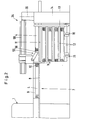
- Fig. 1 there is a first cutting station 1 in the form of a face-cutting machine with an indicated cutting line 2.
- Block strips 4 are separated from the stack 3 from large-area sheet material, the stack 3 being aligned in the usual way on a side stop 5 and by a feed device 6 be advanced step by step.
- the block strips 4 are collected according to FIGS. 1 and 2 at a loading and pre-alignment station 7 on a transport plate 8. At their edges there are two stops 9 and 10 which run perpendicular to one another and by means of which the block strips 4 can be placed next to one another on the transport plate 8 in a perfectly aligned manner.
- the loaded transport plate 8 can be moved from the loading and pre-alignment station to the right into the! 1 and 2 are moved after the stop 9 has moved away in the direction of arrow a and the stop 10 has been moved downward in the direction of arrow b.
- the loaded transport plate 8 arrives at a transfer station 11, which is formed by a currently effective tier 12 of a buffer shelf 13. This is assigned a lifting device 14 with which the floors 12 can each be brought to the height required for the transfer of the transport plate 8.
- the buffer shelf 13 is mounted on wheels 15 and 16 so that it can be replaced as a whole and can also be loaded and unloaded elsewhere.
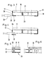
- each tier 12 has two guide rails 17 and 18 running in the loading direction c, between which a transport plate 8 is guided.
- cylindrical rollers 19 are provided, the axes 20 of which extend perpendicular to the loading direction c.
- the rollers are made of plastic, which has a low coefficient of friction.
- the rollers 19 are arranged in three rows and are each mounted in tubular supports 21 with a rectangular cross section.
- the guide rail 17 can be displaced downward by means of a lowering device 22 against the force of a spring, not shown, so that the transport plate 8 can be moved further in the direction of the arrow d.
- the lowering device 22 has two servomotors 23 and 24, here in the form of a pneumatic or hydraulic piston-cylinder unit, each of which has a plunger 25 with an inclined surface 26. When the lowering device 22 is actuated, the inclined surface interacts with the underside 27 of an opening 28 in the guide rail 17 in order to urge the guide rail downward.
- a stop device 29 is provided (FIGS. 5, 6 and 8).
- This stop device consists of a recess 30 on the underside of the transport plate 8 and a catch 31 held on the guide rail 17, which is loaded by a spring 32.
- An inclined surface 33 is connected upstream of the depression, so that the catch 31 is first pressed down before it snaps into the depression 30.
- the catch 31 also emerges from the depression 30, so that the transport plate 8 is thereby released.
- the transfer station 11 connects directly to a second cutting station 34, the cutting line 35 of which is again only indicated by dash-dotted lines.
- This cutting station has a work surface which consists of an input field 36, a work field 37 and an output field 38.
- the input field 36 which roughly comprises the area B1
- the working area 37 which roughly comprises the area B2
- the exit area 38 which can extend over the area B3, serves to receive the finished cut stacks . Where this is desired, these stacks can be processed further in additional processing stations, for example in a bundling station 40 and / or a punching station 41, as is indicated by dash-dotted lines in FIG. 1.
- the cutting station 34 has two guides 42 and 43 of such a length that they extend beyond the actual input field 36.
- the transport plate 8 is moved by a motor.
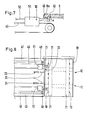
- a motor 44 drives an endless chain 46 via a drive wheel 45, which chain is guided near the transfer station 11 via a further deflection wheel 47.
- a coupling piece 48 is attached to the chain 46 and can engage in a recess 49 in the transport plate 8.
- the coupling piece 48 is mounted about an axis 50 in the housing of a servomotor 51.
- the servomotor can be operated pneumatically, hydraulically or electrically. If energy is supplied to it via a supply line 52, the coupling piece 48 pivots in the direction of arrow e into the coupling position illustrated in FIG. 7.
- the transport plate 8 can in the direction of arrow d from the transfer station 11 in the area of Input field 36 are drawn.
- a height-adjustable stop 53 which is raised by means of an inclined surface 8a (FIG. 7) from the transport plate 8 moving in the direction d and to which a proximity initiator 54 is assigned.
- the motor 44 is switched off.
- the block strips now have a defined position within the input field 36 of the cutting station 34.
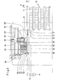
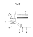
- a feed device 55 has individual segments 56. These can be pivoted upwards from an active position (fully extended in FIG. 10) about an axis 57 arranged behind them into an inactive position (dash-dotted lines in FIG. 10). 1, the effective width of the feed device 55 corresponds to three times the width of a block strip 4. If the feed device 55 is now moved along its path 58 by a desired amount, only the first three block strips are taken along and onto the Work field 37 transferred. By adjusting the effective width of the feed device, it can be adapted to any other number or width of the block strips.
- the pressure slide 39 which presses the block strips against the stop 53 near the cutting line 35, is effective on the working field in order to make a final alignment.
- This pressure slide 39 is actuated by means of a servomotor 60 in the direction of arrow d and can be displaced in height by means of a servomotor 61.
- the carriage i 62 carrying the arrangement can be moved horizontally along a guide 63.
- a hold-down device 64 is also provided, which is also held by the carriage 62 and can be pressed down by means of servomotors 65. He holds the next block strip so that the first three block strips. can be moved without affecting the subsequent block strips.
- Another pressure slide 66 which can be moved in the direction of arrow f, acts on the end faces of the block strips so that they are aligned with the active segments 56 of the feed device 55.
- the transverse alignment with the pressure slide 39 and the longitudinal alignment with the pressure slide 66 require only a minimal outlay, since the advanced block strips already have a defined position. Then a very precise cut is made.
- the block strips are then advanced step by step by means of the feed device 55 and cut in the transverse direction after each new alignment. As soon as the block strips treated in this way have been cut, the feed device 55 returns to its starting position.
- the motor 44 moves the transport plate 8 further in the direction of the arrow d until the now most forward block strip 4 is detected by the proximity switch 54 and the motor is switched off again.
- the step-by-step advancement and the alignment preceding each cut are then repeated by means of the pressure slides 39 and 66.
- a modified loading and pre-alignment station 107 is illustrated in FIG. 11.
- Transport plate 8 and block strips 4 are unchanged.
- the auxiliary stop 110 cannot be lowered downwards, but can be lifted horizontally from the block strip 4 in the direction of the arrow g and then moved upwards along the arrow h by an actuator so that it takes up the position shown in broken lines.
- the loaded transport plate 8 can then be moved under the auxiliary stop 110.
- an air streaking device 64 which has a hold-down device 65 which is formed by a bar 65 of the auxiliary stop 110 which overlaps the transport plate 8.
- This hold-down device can be moved downward by the path i after the moving-off movement g in order to press the block strips 4 onto one edge on the transport plate 8.
- a servomotor 66 in the form of a pneumatic cylinder is provided to generate the contact pressure and to carry out the movements h and i.
- an air spreading element 67 in the form of a rotatable spreading roller which is held on a guide 69 with the interposition of a servomotor 68 in the form of a pneumatic cylinder, so that it is lowered onto the block strips 4 along the path k and then along the transport plate 8 the surface of the block stack 4 can be moved on the way 1, whereby the air is pressed out between the sheets of the block stack. This almost completely prevents the sheets from moving against each other.
- the spreading roller 67 is then returned to the starting position via the paths m and n.
- the vertical movements are made using the Actuator 68, which causes horizontal movements with the aid of an only indicated motor 70 and an associated chain drive.
- the second cutting station and the feed arrangement can be operated largely automatically. There is also the possibility of automatically forwarding the stack of labels located on the exit field 38 to the bundling station 40 or punching station 41. As a result, a single operator is sufficient for the production of the labels, who produces the block strips at the cutting station 1, places them correctly on the loading and pre-aligning station 7 and otherwise only monitors the automatic process of the system.
- the empty transport plates on the side of the input field 36 facing away from the buffer shelf 13 can be removed.
- the servomotors required for the automatic sequence can be operated pneumatically, hydraulically, mechanically, electrically or in any other known manner.
- the loading station can be spatially separated from the pre-alignment station. Conversely, it is also possible to combine the loading station, the pre-alignment station and the transfer station with one another.
- the transport plate 8 can also have air holes in a known manner, in particular only when loaded by a stack of opening air holes, which, when the transport plate 8 is loaded in the station 7 and possibly also when this plate is unloaded, by the active parts of the feed device 55 with a compressed air source get connected.
Landscapes
- Life Sciences & Earth Sciences (AREA)
- Forests & Forestry (AREA)
- Engineering & Computer Science (AREA)
- Mechanical Engineering (AREA)
- Pile Receivers (AREA)
- Feeding Of Workpieces (AREA)
- Feeding Of Articles By Means Other Than Belts Or Rollers (AREA)
- Branching, Merging, And Special Transfer Between Conveyors (AREA)
Applications Claiming Priority (2)
| Application Number | Priority Date | Filing Date | Title |
|---|---|---|---|
| DE3613315 | 1986-04-19 | ||
| DE19863613315 DE3613315A1 (de) | 1986-04-19 | 1986-04-19 | Anordnung zum zufuehren von gestapeltem, blattfoermigen gut zu einer weiterverarbeitungsstation, insbesondere schneidstation |
Publications (3)
| Publication Number | Publication Date |
|---|---|
| EP0242762A2 true EP0242762A2 (fr) | 1987-10-28 |
| EP0242762A3 EP0242762A3 (en) | 1989-12-06 |
| EP0242762B1 EP0242762B1 (fr) | 1991-07-03 |
Family
ID=6299100
Family Applications (1)
| Application Number | Title | Priority Date | Filing Date |
|---|---|---|---|
| EP87105448A Expired - Lifetime EP0242762B1 (fr) | 1986-04-19 | 1987-04-13 | Dispositif pour conduire une pile de feuilles à un dispositif de coupe |
Country Status (5)
| Country | Link |
|---|---|
| US (1) | US5150647A (fr) |
| EP (1) | EP0242762B1 (fr) |
| JP (1) | JPH0825158B2 (fr) |
| DE (2) | DE3613315A1 (fr) |
| ES (1) | ES2023375B3 (fr) |
Cited By (5)
| Publication number | Priority date | Publication date | Assignee | Title |
|---|---|---|---|---|
| EP0453935A1 (fr) * | 1990-04-26 | 1991-10-30 | Wolfgang Mohr | Procédé et dispositif pour transporter des matériaux en feuilles superposées d'une table de réception vers une table d'alimentation dans une machine de coupe |
| EP0455134A1 (fr) * | 1990-05-03 | 1991-11-06 | GIBEN IMPIANTI S.p.A. | Appareil pour transférer des piles de panneaux dans une installation de découpage de type angulaire |
| EP0641631A1 (fr) * | 1993-08-26 | 1995-03-08 | Kolbus GmbH & Co. KG | Méthode et machine pour la coupe sur les trois côtés de piles de livres, brochures ou similaires |
| EP2179823A1 (fr) | 2008-10-10 | 2010-04-28 | Adolf Mohr Maschinenfabrik GmbH & Co. KG | Procédé de production de piles utilitaires à l'aide d'une machine de coupe plane |
| EP2228182A1 (fr) | 2009-03-11 | 2010-09-15 | Adolf Mohr Maschinenfabrik GmbH & Co. KG | Procédé de production de piles utiles à l'aide d'une machine de découpage de plans |
Families Citing this family (11)
| Publication number | Priority date | Publication date | Assignee | Title |
|---|---|---|---|---|
| DE3941273A1 (de) * | 1989-12-14 | 1991-06-20 | Rockwool Mineralwolle | Verfahren zur waerme- und/oder schalldaemmung von gebaeuden |
| JP2694585B2 (ja) * | 1991-12-19 | 1997-12-24 | 富士写真フイルム株式会社 | 断裁装置、空気抜き装置及びシート重なり防止装置 |
| US5694823A (en) * | 1994-10-18 | 1997-12-09 | The Challenge Machinery Company | Document trimming apparatus |
| DE19523699A1 (de) * | 1995-06-29 | 1997-01-09 | Will E C H Gmbh & Co | Vorrichtung zum Entfernen von Lufteinschlüssen aus Papierstapeln |
| EP0936166A1 (fr) * | 1998-02-10 | 1999-08-18 | E.I. Du Pont De Nemours And Company | Dispositif de coupe à haute vitesse |
| EP1018409B1 (fr) * | 1998-12-28 | 2003-03-26 | Adolf Mohr Maschinenfabrik GmbH & Co. KG | Procédé pour la formation et le traitement ultérieur de petites piles de produits en feuilles |
| DE19926073C2 (de) * | 1999-06-08 | 2001-05-10 | Polar Bandpack Buendelmaschine | Vorrichtung zur Handhabung von Planschnittprodukten |
| EP1172185A1 (fr) * | 2000-07-14 | 2002-01-16 | Adolf Mohr Maschinenfabrik GmbH & Co. KG | Dispositif pour la coupe de matériaux en feuille |
| US7097727B2 (en) * | 2003-05-06 | 2006-08-29 | 3M Innovative Properties Company | Inline accumulating die padder |
| JP4780604B2 (ja) * | 2005-10-07 | 2011-09-28 | カール事務器株式会社 | 用紙の位置決め機構 |
| CN118288017A (zh) * | 2024-04-10 | 2024-07-05 | 斯美科智能制造(杭州)有限公司 | 一种磁流体轴承柱的磁体安装机 |
Family Cites Families (25)
| Publication number | Priority date | Publication date | Assignee | Title |
|---|---|---|---|---|
| US1883449A (en) * | 1929-08-10 | 1932-10-18 | Box Blank Corp | Packing process for silk yarn and the like |
| US2376470A (en) * | 1944-02-26 | 1945-05-22 | Int Paper Co | Sheet cutter |
| US2834388A (en) * | 1954-10-04 | 1958-05-13 | Us Slicing Machine Co Inc | Slicing machine slicer, stacker, and weigher |
| DE1144685B (de) * | 1959-11-12 | 1963-03-07 | Southworth Machine Co | Einrichtung zum Foerdern von Papierbogenstoessen, z. B. in eine Papierschneidemaschine |
| US3165956A (en) * | 1962-05-02 | 1965-01-19 | Miehle Goss Dexter Inc | Paper pile aligner for automatic cutter |
| US3424044A (en) * | 1966-03-10 | 1969-01-28 | Miehle Goss Dexter Inc | Continuous three-knife trimmer |
| DE2225910A1 (de) * | 1972-05-27 | 1973-12-13 | Baumann Heinrich | Vorrichtung zum aufeinandersetzen von teilstapeln aus papierbogen zu einem gesamtstapel |
| GB1439310A (en) * | 1973-10-26 | 1976-06-16 | Minolta Camera Kko | Printing paper cutting device for use in copying apparatus |
| US4034636A (en) * | 1975-07-16 | 1977-07-12 | Gerber Garment Technology, Inc. | Method and apparatus for placing a multi-ply layup of sheet material on a work table |
| US4036381A (en) * | 1975-09-05 | 1977-07-19 | International Business Machines Corporation | Apparatus for transferring sample holders relative to a movable magazine |
| DE2723162C2 (de) * | 1977-05-23 | 1987-03-26 | Karl Mohr | Verfahren zum Entlüften eines auf einem Rütteltisch gerüttelten Teilstapels zu schneidenden Gutes und Vorrichtung zur Durchführung des Verfahrens |
| DE2758291C3 (de) * | 1977-12-27 | 1980-07-10 | Jagenberg-Werke Ag, 4000 Duesseldorf | Stapelwechselvorrichtung |
| US4364311A (en) * | 1980-09-05 | 1982-12-21 | Platt Iii James B | Precision trimming and precision cross-cutting apparatus and method for bulk material |
| CH639045A5 (fr) * | 1981-02-03 | 1983-10-31 | Bobst Sa | Dispositif pour introduire des paquets de feuilles dans une machine les travaillant. |
| JPS58102699A (ja) * | 1981-12-16 | 1983-06-18 | 株式会社共同精機工作所 | シ−トの断裁処理方法 |
| CH663750A5 (de) * | 1982-04-08 | 1988-01-15 | De La Rue Giori Sa | Verfahren und vorrichtung zur herstellung druckfrischer, numerierter und auf format geschnittener wertscheine. |
| US4509417A (en) * | 1983-02-12 | 1985-04-09 | E.C.H. Will (Gmbh & Co.) | Apparatus for expelling air from stacks of paper sheets or the like |
| US4588341A (en) * | 1983-07-08 | 1986-05-13 | Motoda Denshi Kogyo Kabushiki Kaisha | Article delivery apparatus |
| SE438139B (sv) * | 1983-08-19 | 1985-04-01 | Ibm Svenska Ab | Docknings- och fixeringssystem for en robot eller liknande system for dockning och fixering av en pallett som har forts till en approximativ arbetsposition |
| US4720463A (en) * | 1985-03-01 | 1988-01-19 | Sherwood Medical Company | Automated microbiological testing apparatus |
| DE3540203C2 (de) * | 1985-11-13 | 1993-12-09 | Will E C H Gmbh & Co | Vorrichtung zum Fördern von Papierstapeln |
| US4641555A (en) * | 1986-01-31 | 1987-02-10 | Johnson Dewey A | Paper handling system |
| DE3644872A1 (de) * | 1986-02-05 | 1987-09-03 | Womako Masch Konstr | Planschneider zum querabtrennen von papierstapeln |
| DE3623004A1 (de) * | 1986-07-09 | 1988-01-28 | Wolfgang Mohr | Planschneidemaschine |
| US4984516A (en) * | 1988-10-07 | 1991-01-15 | Attilio Scalzitti | Apparatus for removing fluid from overlapping sheets of material |
-
1986
- 1986-04-19 DE DE19863613315 patent/DE3613315A1/de active Granted
-
1987
- 1987-04-13 ES ES87105448T patent/ES2023375B3/es not_active Expired - Lifetime
- 1987-04-13 EP EP87105448A patent/EP0242762B1/fr not_active Expired - Lifetime
- 1987-04-13 DE DE8787105448T patent/DE3771114D1/de not_active Expired - Lifetime
- 1987-04-17 JP JP62096100A patent/JPH0825158B2/ja not_active Expired - Lifetime
-
1989
- 1989-10-26 US US07/427,979 patent/US5150647A/en not_active Expired - Lifetime
Cited By (6)
| Publication number | Priority date | Publication date | Assignee | Title |
|---|---|---|---|---|
| EP0453935A1 (fr) * | 1990-04-26 | 1991-10-30 | Wolfgang Mohr | Procédé et dispositif pour transporter des matériaux en feuilles superposées d'une table de réception vers une table d'alimentation dans une machine de coupe |
| EP0455134A1 (fr) * | 1990-05-03 | 1991-11-06 | GIBEN IMPIANTI S.p.A. | Appareil pour transférer des piles de panneaux dans une installation de découpage de type angulaire |
| EP0641631A1 (fr) * | 1993-08-26 | 1995-03-08 | Kolbus GmbH & Co. KG | Méthode et machine pour la coupe sur les trois côtés de piles de livres, brochures ou similaires |
| EP2179823A1 (fr) | 2008-10-10 | 2010-04-28 | Adolf Mohr Maschinenfabrik GmbH & Co. KG | Procédé de production de piles utilitaires à l'aide d'une machine de coupe plane |
| EP2228182A1 (fr) | 2009-03-11 | 2010-09-15 | Adolf Mohr Maschinenfabrik GmbH & Co. KG | Procédé de production de piles utiles à l'aide d'une machine de découpage de plans |
| US8387498B2 (en) | 2009-03-11 | 2013-03-05 | Adolf Mohr Maschinenfabrik Gmbh & Co. Kg | Method for cutting stacks of sheet material |
Also Published As
| Publication number | Publication date |
|---|---|
| DE3771114D1 (de) | 1991-08-08 |
| DE3613315A1 (de) | 1987-10-22 |
| JPS62249843A (ja) | 1987-10-30 |
| US5150647A (en) | 1992-09-29 |
| DE3613315C2 (fr) | 1989-06-22 |
| EP0242762B1 (fr) | 1991-07-03 |
| JPH0825158B2 (ja) | 1996-03-13 |
| EP0242762A3 (en) | 1989-12-06 |
| ES2023375B3 (es) | 1992-01-16 |
Similar Documents
| Publication | Publication Date | Title |
|---|---|---|
| EP0242763B1 (fr) | Dispositif pour couper des feuilles empilées | |
| EP0242762B1 (fr) | Dispositif pour conduire une pile de feuilles à un dispositif de coupe | |
| EP2243606B1 (fr) | Installation de fabrication de plaques en lamelles de bois et procédé destiné à la fabrication de telles plaques | |
| DE2931780A1 (de) | Vorrichtung zum aufteilen einer platte in kleinformatige zuschnitte | |
| EP0494404A1 (fr) | Appareil d'alimentation des plaques pour scies à découper des plaques | |
| EP0252418B1 (fr) | Guillotine | |
| DE2753668C2 (de) | Verfahren und Vorrichtung zur Bildung eines in Schneid- und Stanzmaschinen verarbeitungsfähigen Stapels aus Bogen | |
| DE3515729C2 (fr) | ||
| DE69128660T2 (de) | Einrichtung zum Sortieren von kleinen, aus Blechen gestanzten Werkstücken | |
| DE3716666C2 (de) | Plattenaufteilanlage mit einer Längssäge und einer Quersäge | |
| EP1018408B1 (fr) | Guillotine pour couper des produits en feuilles empilées | |
| DE3613462A1 (de) | Vorrichtung zum be- und entladen eines stapellifts | |
| DE4224010A1 (de) | Vorrichtung zum handhaben von bahn- oder bogenmaterial aus papier | |
| DE8014325U1 (de) | Maschine zum rillen von platten, insbesondere fuer gedruckte schaltungen | |
| DE60102097T2 (de) | Auslegerstation einer Formpresse und Werkzeugsatz für eine solche Station | |
| EP0453806B1 (fr) | Installation pour empiler des pièces constituées d'éléments plats séparés ou de paquets desdits éléments plats | |
| DE19926822A1 (de) | Plattenwechselvorrichtung | |
| EP0751086B1 (fr) | Dispositif pour extraire les inclusions d'air de piles de papier | |
| DE2134375A1 (de) | Selbsttaetig arbeitende vorrichtung zum beschicken von schneidemaschinen mit gestapeltem gut und zum abfuehren und stapeln des geschnittenen gutes mittels zweier der maschine zugeordneter liftsaeulen, an denen ein verfahrbarer traeger zur aufnahme des schneidgutes angeordnet ist | |
| EP0489681B1 (fr) | Procédé et dispositif pour déplacer des pièces en forme de bandes ou de panneaux, empilés et juxtaposés sur une surface de support à faible coefficient de frottement | |
| DE1953150B2 (de) | Vorrichtung zum Ritzen von Glas tafeln | |
| DE3632018A1 (de) | Aufteilanlage fuer plattenfoermige werkstuecke | |
| DE3317084C2 (fr) | ||
| DE69611135T2 (de) | Rahmen mit Schnellspanneinrichtung für Stanzwerkzeuge | |
| AT410541B (de) | Vorrichtung zum stapeln von formatzuschnitten mit einem verfahrbaren gabelwagen |
Legal Events
| Date | Code | Title | Description |
|---|---|---|---|
| PUAI | Public reference made under article 153(3) epc to a published international application that has entered the european phase |
Free format text: ORIGINAL CODE: 0009012 |
|
| AK | Designated contracting states |
Kind code of ref document: A2 Designated state(s): BE CH DE ES FR GB IT LI NL SE |
|
| PUAL | Search report despatched |
Free format text: ORIGINAL CODE: 0009013 |
|
| AK | Designated contracting states |
Kind code of ref document: A3 Designated state(s): BE CH DE ES FR GB IT LI NL SE |
|
| 17P | Request for examination filed |
Effective date: 19900120 |
|
| 17Q | First examination report despatched |
Effective date: 19900828 |
|
| GRAA | (expected) grant |
Free format text: ORIGINAL CODE: 0009210 |
|
| AK | Designated contracting states |
Kind code of ref document: B1 Designated state(s): BE CH DE ES FR GB IT LI NL SE |
|
| ITF | It: translation for a ep patent filed | ||
| REF | Corresponds to: |
Ref document number: 3771114 Country of ref document: DE Date of ref document: 19910808 |
|
| GBT | Gb: translation of ep patent filed (gb section 77(6)(a)/1977) | ||
| ET | Fr: translation filed | ||
| REG | Reference to a national code |
Ref country code: ES Ref legal event code: FG2A Ref document number: 2023375 Country of ref document: ES Kind code of ref document: B3 |
|
| PLBE | No opposition filed within time limit |
Free format text: ORIGINAL CODE: 0009261 |
|
| STAA | Information on the status of an ep patent application or granted ep patent |
Free format text: STATUS: NO OPPOSITION FILED WITHIN TIME LIMIT |
|
| 26N | No opposition filed | ||
| EAL | Se: european patent in force in sweden |
Ref document number: 87105448.2 |
|
| REG | Reference to a national code |
Ref country code: CH Ref legal event code: PUE Owner name: WOLFGANG MOHR TRANSFER- ADOLF MOHR MASCHINENFABRIK |
|
| REG | Reference to a national code |
Ref country code: FR Ref legal event code: TP |
|
| NLS | Nl: assignments of ep-patents |
Owner name: ADOLF MOHR MASCHINENFABRIK GMBH & CO. KG |
|
| REG | Reference to a national code |
Ref country code: GB Ref legal event code: 732E |
|
| REG | Reference to a national code |
Ref country code: ES Ref legal event code: PC2A |
|
| PGFP | Annual fee paid to national office [announced via postgrant information from national office to epo] |
Ref country code: SE Payment date: 20010309 Year of fee payment: 15 |
|
| PGFP | Annual fee paid to national office [announced via postgrant information from national office to epo] |
Ref country code: FR Payment date: 20010315 Year of fee payment: 15 |
|
| PGFP | Annual fee paid to national office [announced via postgrant information from national office to epo] |
Ref country code: BE Payment date: 20010327 Year of fee payment: 15 |
|
| PGFP | Annual fee paid to national office [announced via postgrant information from national office to epo] |
Ref country code: ES Payment date: 20010409 Year of fee payment: 15 |
|
| PGFP | Annual fee paid to national office [announced via postgrant information from national office to epo] |
Ref country code: GB Payment date: 20010411 Year of fee payment: 15 |
|
| PGFP | Annual fee paid to national office [announced via postgrant information from national office to epo] |
Ref country code: CH Payment date: 20010426 Year of fee payment: 15 |
|
| PGFP | Annual fee paid to national office [announced via postgrant information from national office to epo] |
Ref country code: NL Payment date: 20010430 Year of fee payment: 15 |
|
| REG | Reference to a national code |
Ref country code: GB Ref legal event code: IF02 |
|
| PG25 | Lapsed in a contracting state [announced via postgrant information from national office to epo] |
Ref country code: GB Free format text: LAPSE BECAUSE OF NON-PAYMENT OF DUE FEES Effective date: 20020413 |
|
| PG25 | Lapsed in a contracting state [announced via postgrant information from national office to epo] |
Ref country code: SE Free format text: LAPSE BECAUSE OF NON-PAYMENT OF DUE FEES Effective date: 20020414 Ref country code: ES Free format text: LAPSE BECAUSE OF NON-PAYMENT OF DUE FEES Effective date: 20020414 |
|
| PG25 | Lapsed in a contracting state [announced via postgrant information from national office to epo] |
Ref country code: LI Free format text: LAPSE BECAUSE OF NON-PAYMENT OF DUE FEES Effective date: 20020430 Ref country code: CH Free format text: LAPSE BECAUSE OF NON-PAYMENT OF DUE FEES Effective date: 20020430 Ref country code: BE Free format text: LAPSE BECAUSE OF NON-PAYMENT OF DUE FEES Effective date: 20020430 |
|
| PG25 | Lapsed in a contracting state [announced via postgrant information from national office to epo] |
Ref country code: NL Free format text: LAPSE BECAUSE OF NON-PAYMENT OF DUE FEES Effective date: 20021101 |
|
| EUG | Se: european patent has lapsed |
Ref document number: 87105448.2 |
|
| GBPC | Gb: european patent ceased through non-payment of renewal fee |
Effective date: 20020413 |
|
| REG | Reference to a national code |
Ref country code: CH Ref legal event code: PL |
|
| PG25 | Lapsed in a contracting state [announced via postgrant information from national office to epo] |
Ref country code: FR Free format text: LAPSE BECAUSE OF NON-PAYMENT OF DUE FEES Effective date: 20021231 |
|
| NLV4 | Nl: lapsed or anulled due to non-payment of the annual fee |
Effective date: 20021101 |
|
| REG | Reference to a national code |
Ref country code: FR Ref legal event code: ST |
|
| REG | Reference to a national code |
Ref country code: ES Ref legal event code: FD2A Effective date: 20030514 |
|
| PGFP | Annual fee paid to national office [announced via postgrant information from national office to epo] |
Ref country code: DE Payment date: 20040416 Year of fee payment: 18 |
|
| PG25 | Lapsed in a contracting state [announced via postgrant information from national office to epo] |
Ref country code: IT Free format text: LAPSE BECAUSE OF NON-PAYMENT OF DUE FEES;WARNING: LAPSES OF ITALIAN PATENTS WITH EFFECTIVE DATE BEFORE 2007 MAY HAVE OCCURRED AT ANY TIME BEFORE 2007. THE CORRECT EFFECTIVE DATE MAY BE DIFFERENT FROM THE ONE RECORDED. Effective date: 20050413 |
|
| PG25 | Lapsed in a contracting state [announced via postgrant information from national office to epo] |
Ref country code: DE Free format text: LAPSE BECAUSE OF NON-PAYMENT OF DUE FEES Effective date: 20051101 |