EP0242764A2 - Méthode et dispositif pour le transfert décentralisé de la fonction maître dans des systèmes multiordinateurs avec un canal de transmission en boucle - Google Patents
Méthode et dispositif pour le transfert décentralisé de la fonction maître dans des systèmes multiordinateurs avec un canal de transmission en boucle Download PDFInfo
- Publication number
- EP0242764A2 EP0242764A2 EP87105454A EP87105454A EP0242764A2 EP 0242764 A2 EP0242764 A2 EP 0242764A2 EP 87105454 A EP87105454 A EP 87105454A EP 87105454 A EP87105454 A EP 87105454A EP 0242764 A2 EP0242764 A2 EP 0242764A2
- Authority
- EP
- European Patent Office
- Prior art keywords
- control signal
- transmission
- input
- output
- gate circuit
- Prior art date
- Legal status (The legal status is an assumption and is not a legal conclusion. Google has not performed a legal analysis and makes no representation as to the accuracy of the status listed.)
- Ceased
Links
- 230000005540 biological transmission Effects 0.000 title claims abstract description 125
- 238000000034 method Methods 0.000 title claims abstract description 29
- 238000012546 transfer Methods 0.000 title description 8
- 230000010365 information processing Effects 0.000 claims abstract description 21
- 230000011664 signaling Effects 0.000 claims description 8
- 238000012545 processing Methods 0.000 claims description 3
- 230000008054 signal transmission Effects 0.000 claims description 2
- 230000001960 triggered effect Effects 0.000 claims description 2
- 230000001934 delay Effects 0.000 abstract 1
- 238000012432 intermediate storage Methods 0.000 description 3
- 238000004891 communication Methods 0.000 description 2
- 230000003111 delayed effect Effects 0.000 description 2
- 230000001419 dependent effect Effects 0.000 description 2
- 238000001514 detection method Methods 0.000 description 2
- 238000010586 diagram Methods 0.000 description 2
- 230000002349 favourable effect Effects 0.000 description 2
- 238000003780 insertion Methods 0.000 description 2
- 230000037431 insertion Effects 0.000 description 2
- 230000003213 activating effect Effects 0.000 description 1
- 230000004913 activation Effects 0.000 description 1
- 238000013475 authorization Methods 0.000 description 1
- 230000000694 effects Effects 0.000 description 1
- 238000011156 evaluation Methods 0.000 description 1
- 238000004801 process automation Methods 0.000 description 1
- 230000035484 reaction time Effects 0.000 description 1
- 230000003068 static effect Effects 0.000 description 1
- 238000003860 storage Methods 0.000 description 1
- 230000002123 temporal effect Effects 0.000 description 1
Images
Classifications
-
- H—ELECTRICITY
- H04—ELECTRIC COMMUNICATION TECHNIQUE
- H04L—TRANSMISSION OF DIGITAL INFORMATION, e.g. TELEGRAPHIC COMMUNICATION
- H04L12/00—Data switching networks
- H04L12/28—Data switching networks characterised by path configuration, e.g. LAN [Local Area Networks] or WAN [Wide Area Networks]
- H04L12/42—Loop networks
- H04L12/427—Loop networks with decentralised control
- H04L12/433—Loop networks with decentralised control with asynchronous transmission, e.g. token ring, register insertion
Definitions
- the invention relates to a method and a device for transmitting the master function in multi-computer systems with an annular transmission channel, in which Subscriber stations are connected to each other in series via a unidirectional transmission channel and each have a receiving and a transmitting device and a switching device which interrupts and closes the transmission channel between the receiving and transmitting device, the transmission channel only interrupting the switching devices of the current master station during the user data transmission , all other subscriber stations immediately switch through the received signals to their transmitting devices during data transmission and the transmission of the master function is initiated by control signals sent by the current master station.
- serial transmission systems For data transmission between system components of a multi-computer system for process data processing, process and laboratory automation, office communication, etc. parallel and serial transmission methods are known. In hierarchically structured, spatially distributed decentralized systems, serial transmission systems are primarily used for reasons of data backup, flexibility and to enable the shortest possible transmission paths.
- Priority procedures, the fair allocation and the sequential allocation distinguished.
- process automation systems with hierarchically structured intelligent subscriber stations which also have to exchange messages with each other and have to adhere to a strictly defined reaction time to alarms and messages, only processes with decentralized allocation and as free as possible a request time grid can be considered.
- the ring or multiple ring structure is known for the connection of several subscribers (see, for example, US Pat. No. 4,486,852, US Pat. No. 4,495,617, US Pat. No. 4,501,021, DE-OS 3,150 474, DE-OS 3 012 105 and DD-PS 225 293 as well as Heger / Steusloff / Syrbe: real-time computer system with distributed microprocessors, Fraunhofer Institute for Information and Data Processing, Düsseldorf 1979 and Mahrber: rtp-Seminar Bussysteme, R. Oldenbourg-Verlag , Kunststoff / Vienna 1984).
- Typical decentrally controlled access procedures include the slot procedure, in which sections circulate on the ring, into which messages are written by the sender, which are deleted by the receiver, and the register insertion ring, in which a station willing to send a message telegram between two on the ring inserts existing telegrams, whereby it temporarily stores the subsequent telegram and only sends it after its own.
- Disadvantages are the less flexible reaction to different and changing load cases with the slot procedure with regard to the amount of messages from the stations, since a large part of the channel capacity can be tied up by empty slots and the high effort for the intermediate storage and protection against failures in the register insertion ring.
- Another typical decentrally controlled access procedure ren is the identification procedure (token - passing), in which the transmission authorization is transferred from one subscriber station to the next by means of a special message, the so-called token, and the latter then exercises the transmission right or forwards the token.
- token token
- Each subscriber station willing to send must wait for the token, remove it from the ring after it has been recognized, and send the token again after transmitting its data telegram.
- the advantages of the identifier method are its simplicity, the decentralized access control and the independence of the message length.
- a disadvantage is the necessary temporary storage associated with the recognition of the token in each subscriber station, as a result of which the transmission power of the transmission channel is reduced.
- the invention seeks to remedy this.
- the object of the invention is to provide a method and a device for the decentrally controlled transmission of the master function in decentralized multi-computer systems with an annular transmission channel.
- Each subscriber station in the ring-shaped transmission channel should be completely equal and no monitor station should exist.
- no additional delay should occur in the subscriber stations wishing to transmit, and all subscriber stations should be constructed in a completely identical manner with regard to controlling the master transfer and perform the same functions.
- the master transfer should not be temporarily stored the control signals in the participants willing to send may be required, and reception and transmission of control signals take place essentially simultaneously.
- the method according to the invention for transmitting the master function in decentralized multi-computer systems with an annular transmission channel is one in which Subscriber stations are connected to each other in series via a unidirectional transmission channel and each have a receiving and a transmitting device and a switching device which interrupts and closes the transmission channel between the receiving and transmitting device, the transmission channel only interrupting the switching devices of the current master station during the user data transmission , all other subscriber stations immediately switch through the received signals to their transmitting devices during data transmission and the transmission of the master function is triggered by control signals sent by the current master station, characterized in that three different control signals are used to transmit the master function, a first control signal is sent by the current master station immediately after a data telegram sent by it, all subscriber stations with a transmission request after receiving the first control signal interrupt the transmission channel by opening their switching device, with a second control signal transmitted by the current master station according to the first control signal, the master function is transmitted to the next willing subscriber station following in the transmission direction, the third control signal is sent
- the proposed method steps according to the invention are explained in more detail below:
- the switching devices of all other participants are closed during the user data transmission by the current master.
- the ring-shaped transmission channel thus begins in the transmitter and ends in the receiver of the current master, with all other participants immediately switching through the received information to their transmitter without intermediate storage and are themselves only slaves.
- the first control signal sent by the current master after its data telegram to the transmission channel is transmitted in the same way as the previous user data, which is why a suitable bit combination must be used to prevent the first control signal from occurring in the user data.
- the reception of the first control signal leads to the interruption of the transmission channel in all participants with a request to transmit, so that during the following control phase the transmission channel is structured from a number of point-to-point connections between the participants with a request to transmit and the current master, all participants remain in the state described above without sending request.
- second and third control signals are essentially transmitted simultaneously to the transmission channel, with only the current master second and all participants with a request to send each send a third control signal.
- the master control is transmitted to this subscriber by means of the second control signal, which only reaches the subscriber immediately following in the transmission direction, while all other subscribers willing to send and the current master receive a third control signal and are prompted to close their switching devices, thereby resetting the transmission channel the initial structure assumes, that is, begins and ends in the new current master.
- the method steps described are repeated after each user data transmission, regardless of their length, as a result of which the master function in the ring-shaped multi-computer system constantly rotates in the transmission direction and only the computers with the current transmission request are included in the control of the master transfer.
- the duration of the second control signal must not be selected to be greater than the duration of the third control signal in order to close the switching device of the current master before the second control signal has been sent completely and thus before the master function is transmitted to the next willing participant to avoid.
- the time difference between the end of the transmission of the second control signal and the reception of the second or third control signal by the current master as a result of the structure-related finite ring circulation time is bridged by the fact that the master constantly repeats the second control signal, while the first two and the first and circulate third control signal on the transmission ring.
- the current master station receives the first and second control signals it has sent itself again, which means that it remains the current master station and, if no new request to send can be recorded in the meantime, repeats the transmission of the first and second control signals .
- the time between two successive transmissions of the first two control signals must be greater than or equal to the sum of all the transit times on the transmission ring and the temporal length of the two signals in order to prevent error situations caused by the simultaneous presence of several first and second control signals on the transmission ring could arise.
- bit patterns for the second and for the third control signal so that the two signals are in the first bit position distinguish what the participants already receive information about their specific status (master or slave) during the next data transfer by receiving this bit.
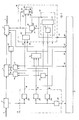
- the device for carrying out the method that achieves the above object has an information processing unit and a control unit for controlling access to the transmission channel is characterized in that the receiving device is connected to a demodulator which has a useful data output and a first, second and third control signal output, of which the useful data output is connected to the information processing unit, the first control signal output is connected to a first input of a first gate circuit, the second control signal output with a first input of a second gate circuit and the third control signal output with a signal input for closing the switching device and with a first stop input of a control signal generator for the first and second control signals are connected, a transmission request signal output of the information processing unit to a second input the first gate circuit and is connected to a second input of the second gate circuit, an output of the first gate circuit is connected to a signal input for opening the switching device and to a start input of a control signal generator for the third control signal, which is connected to a first input of the transmission device, a second input of the transmission device is connected to a serial user data output
- the demodulator expediently consists of a useful data demodulator and three comparators arranged in parallel, the outputs of which are the useful data output and the first, second and third control signal outputs.
- the two stop inputs of the control signal generator for the first and second control signals are linked to one another via an OR circuit; the stop inputs of the signal generator for the second control signal are in parallel at the output of the OR circuit; the output of the information processing unit is connected to the start input of the control signal generator for the first control signal and to the second stop input of the control signal generator for the second control signal for the end signaling of the useful data transmission; the two outputs of the control signal transmitter for the first and the second control signal are connected to the end signaling of the control signal transmission at the start input of the control signal transmitter for the second control signal; and the start input of the control signal generator for the first control signal is also connected to a control signal repetition circuit.
- the control signal repetition circuit advantageously consists of a third gate circuit with three inputs and a timing element, the Control signal output of the demodulator for the first control signal via the timing element to the first input of the gate circuit, the control signal output of the demodulator for the second control signal to the second input of the gate circuit and a feedback output of the switching device are connected to the third input of the gate circuit.
- a timer is advantageously connected to the first control signal output of the demodulator, the output of which is connected to a third input of the second gate circuit and to a second input of a fourth gate circuit which is arranged in front of the signal input for closing the switching device.
- the functioning of the circuit arrangement corresponds to the method.
- the switching device is opened via the comparator circuit for the first control signal and via the first gate circuit when an internal transmission request has already been made at the first gate circuit Signal from the information processing unit is present.
- the signal generator for the third control signal is then activated by activating it via the transmitting device Control signal sent to the next participant with the switching device open, which in turn closes its switching device after it has been detected by means of the third comparator circuit.
- a third control signal is likewise received by the receiving device, which leads to the closing of the switching device, or a second control signal is received, which leads to the control of the second gate circuit via the comparator circuit.
- An output signal is generated at the second gate circuit if there is a transmission request at the same time.
- the output signal of the second gate circuit signals the information processing unit to take over the master function and causes the user data transmission to be started.
- the control unit for the first and second control signals is started by the information processing unit, whereby the transmission of a first and a plurality of second control signals continues until either a third control signal is received or, after receiving a second control signal, the right to transmit is exercised again becomes.
- the number of second control signals following the first control signal is, as already described when the essence of the method according to the invention is described, dependent on the ring circulation time.
- the current master repeats the transmission of the first and second control signals after a certain time by means of the control signal repetition circuit, which is greater than or equal to the ring circulation time and the length of the first two control signals from those already set out Must be reasons.
- this is achieved by using the first and subsequent second signals received via the receiving device and the control signals transmitted via the transmitting device itself after their ring circulation via the control signal repetition circuit for the renewed start of the signal transmitters for the first and second control signals . This ensures that the two control signals are sent again immediately after the ring has circulated.
- control signals for the master transfer or parts thereof do not require intermediate storage, evaluation and subsequent modified or unchanged retransmission by the participants. Rather, the first control signal, which announces the transmission of the master function, passes through all participants without delay, and the participants willing to send, regardless of what they receive, simultaneously send out a third control signal.
- the decentralization of the transmission of the master function achieved with the invention also has advantages with regard to the reliability of such systems to be ensured. For example, in the event of a subscriber failing, the transmission ring is still functional by simply bridging it. It is also easy to insert other subscriber stations of the same type into the transmission ring that is already working.
- the circuit arrangement according to the invention also has the advantage that the information processing units of the participants and thus their software are exempt from access control and that the transmission of the master function is achieved by each participant using relatively simple hardware.
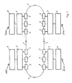
- the switching device (SW1) 4 of the current master is open, and the switching devices (SW2 to SW4) 4 of the other participants (for example 200, 300, 400) are closed , so that the useful data telegrams ND 1 sent to the transmission channel 1 via the transmission device (S1) 3 of the current master 100 pass through all participants on the ring and are received again by the first participant 100 via its reception device 2 (E1) after the ring circulation time has expired.
- the information processing unit 6 of the current master subscriber 100 emits a signal via its output 20, which starts the control signal generator 33 via its start input 37. Irrespective of the fact that the receiving device 2 still receives useful data telegrams ND1, subscriber 100 sends the first control signal immediately after the useful data telegram ND1, which circulates on the transmission ring like the useful data telegrams.
- the first control signal is received by all participants, arrives there in each case in the demodulator 25 and generates a signal at the output of the comparator 26 which controls the first gate circuit 11. It is now assumed that the participants 300 and 400 Via the transmission request outputs 13 of the information processing unit 6, a transmission request signal is simultaneously applied to the first gate circuit 11. These two participants open their AND gates and thus their switching devices 4 via the signal inputs 15. In this way, the transmission channel is divided into three point-to-point connections between the participants 100 and 300, 300 and 400 as well as 400 and 100 (The switching device of the participant not willing to send (200 in the example) remains closed).
- second control signals are sent by subscriber 100 and the third control signal by subscribers 300 and 400, respectively.
- first participant 100 After the first control signal has been sent, the control signal generator 33 generates an end signal at the output 35, which starts the control signal generator 34 via the start input 38, which then sends the second control signal.
- the control signal generator 34 is constantly restarted via the output 36, as a result of which further second control signals reach the receiving device 2 of the subscriber 300 via the transmission channel 1.
- Attendees 300 and 400 The signal present at the output of the first gate circuit 11 starts the control signal generator 16, which in each case generates the third control signal.
- the second control signals sent by subscriber 1 are identified by comparator 27 of subscriber 300, as a result of which second gate circuit 14 is activated and, via input 24 of information processing unit 6, the command for starting the transmission of useful data is issued via its serial useful data output 17.
- the participants 400 and 100 each received the third control signal and closed their switching devices 4 via the comparators 28 and the signal inputs 12.
- the stop inputs 31, 32 of the control signal transmitters 33, 34 have been activated by the receipt of the third control signal, whereby subscriber 100 immediately stops sending these signals.
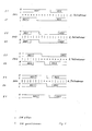
- subscriber 100 bridged the time until reception of useful data telegrams ND3 from subscriber 300 (FIG. 3) with the transmission of the second control signals.
- the current master receives the first and the following second control signals their circulation itself again.
- the transmission of the first two control signals must be repeated, the time period t from the start of a transmission to the beginning of the next transmission must be greater than or equal to the ring circulation time and the length of the two signals in order for a simultaneous presence of several first control signals on the Prevent ring.
- control signal repetition circuit 40 stops the cyclical transmission of second control signals via the second stop input 39 of the control signal generator 34 and at the same time restarts the control signal generator 33 via the start input 37 after the time period t.
- the information for the control signal repetition circuit 40 is advantageously obtained from the reception of the first and the second control signal following the first after their circulation on the transmission ring.
- the output signal of the comparator 26 is delayed by means of the timer 42 so that it is present at the third gate circuit 41 at the same time as the output signal of the comparator 27.
- a favorable selection of the bit combinations for the control signals is made possible in that the above-described effect of a received second or third control signal can only occur after a first control signal has been received beforehand.
- This dependency is achieved by ANDing the output signal of the comparator 28 in the fourth gate circuit 44 and the output signal of the comparator 27 in the second gate circuit 14, each with the output signal of the comparator 26 correspondingly delayed by the timing element 21.
- the only requirement that must be met is that the bit combination of the first control signal must not appear in the user data telegrams, while the bit combinations of the second and third control signals are each free can be selected, which can be shortened to a different bit position.
Landscapes
- Engineering & Computer Science (AREA)
- Computer Networks & Wireless Communication (AREA)
- Signal Processing (AREA)
- Small-Scale Networks (AREA)
Applications Claiming Priority (2)
| Application Number | Priority Date | Filing Date | Title |
|---|---|---|---|
| DD289048 | 1986-04-14 | ||
| DD28904886A DD248206A1 (de) | 1986-04-14 | 1986-04-14 | Verfahren und schaltungsanordnung zur dezentralen steuerung des mastertransfers in ringfoermig strukturierten mehrrechnersystemen |
Publications (2)
| Publication Number | Publication Date |
|---|---|
| EP0242764A2 true EP0242764A2 (fr) | 1987-10-28 |
| EP0242764A3 EP0242764A3 (fr) | 1990-01-24 |
Family
ID=5578120
Family Applications (1)
| Application Number | Title | Priority Date | Filing Date |
|---|---|---|---|
| EP87105454A Ceased EP0242764A3 (fr) | 1986-04-14 | 1987-04-13 | Méthode et dispositif pour le transfert décentralisé de la fonction maítre dans des systèmes multiordinateurs avec un canal de transmission en boucle |
Country Status (2)
| Country | Link |
|---|---|
| EP (1) | EP0242764A3 (fr) |
| DD (1) | DD248206A1 (fr) |
Cited By (1)
| Publication number | Priority date | Publication date | Assignee | Title |
|---|---|---|---|---|
| WO2003101051A1 (fr) * | 2002-05-23 | 2003-12-04 | International Business Machines Corporation | Appareil, procede et programme informatique pour reserver des ressources dans des systemes de communication |
Family Cites Families (2)
| Publication number | Priority date | Publication date | Assignee | Title |
|---|---|---|---|---|
| US3732543A (en) * | 1971-06-30 | 1973-05-08 | Ibm | Loop switching teleprocessing method and system using switching interface |
| US4633468A (en) * | 1984-09-14 | 1986-12-30 | International Business Machines Corp. | Detecting and recovering from fault condition in a serial loop data transmission system |
-
1986
- 1986-04-14 DD DD28904886A patent/DD248206A1/de not_active IP Right Cessation
-
1987
- 1987-04-13 EP EP87105454A patent/EP0242764A3/fr not_active Ceased
Cited By (4)
| Publication number | Priority date | Publication date | Assignee | Title |
|---|---|---|---|---|
| WO2003101051A1 (fr) * | 2002-05-23 | 2003-12-04 | International Business Machines Corporation | Appareil, procede et programme informatique pour reserver des ressources dans des systemes de communication |
| US7126963B2 (en) | 2002-05-23 | 2006-10-24 | International Business Machines Corporation | Apparatus, method and computer program to reserve resources in communications system |
| AU2003230036B2 (en) * | 2002-05-23 | 2007-09-13 | International Business Machines Corporation | Apparatus, method and computer program to reserve resources in communications system |
| US7826476B2 (en) | 2002-05-23 | 2010-11-02 | International Business Machines Corporation | Apparatus and method to reserve resources in communications system |
Also Published As
| Publication number | Publication date |
|---|---|
| EP0242764A3 (fr) | 1990-01-24 |
| DD248206A1 (de) | 1987-07-29 |
Similar Documents
| Publication | Publication Date | Title |
|---|---|---|
| DE3750967T2 (de) | Steuerung von verteilten Taktimpulsen in einer verteilten Digital-Vermittlungsanlage. | |
| DE3750647T2 (de) | Netz mit Jetonübergabe. | |
| DE68925447T2 (de) | Steuerungsverfahren für verteiltes Verarbeitungssystem | |
| DE3413473C2 (fr) | ||
| DE69021186T2 (de) | "Master-Slave" industrielles Netzwerk mit Tokenübergabe. | |
| DE69012461T2 (de) | Kommunikationsnetz zwischen Teilnehmereinrichtungen. | |
| EP0570338B1 (fr) | Procédé et dispositif pour la surveillance et la protection d'accès dans les réseaux de communication | |
| DE2628753A1 (de) | Digitaldaten-uebertragungsnetz | |
| DE4032725C2 (de) | Steuerungsverfahren für Kommunikationsantwort | |
| DE19921589C2 (de) | Verfahren zum Betrieb eines Datenübertragungssystems | |
| DE3539510A1 (de) | Verfahren und einrichtung zur uebertragung von nachrichten zwischen verschiedenen stationen ueber ein lokales verteilernetz | |
| DE10112695A1 (de) | TDMA-Kommunikationssystem | |
| EP1399818B1 (fr) | Procede et dispositif de communication dans un systeme informatique reparti tolerant aux erreurs | |
| EP2965560B1 (fr) | Procédé et infrastructure de réseau pour la transmission redondante de messages dans un système en temps réel distribué | |
| DE10246895B3 (de) | Verfahren zur Änderung eines Parameters für den Betrieb eines Netzwerks sowie Teilnehmer zur Durchführung des Verfahrens | |
| DD248206A1 (de) | Verfahren und schaltungsanordnung zur dezentralen steuerung des mastertransfers in ringfoermig strukturierten mehrrechnersystemen | |
| EP0458781B1 (fr) | Procede pour surveiller un reseau informatique | |
| AT408596B (de) | Verfahren zur übertragung von daten in einem kommunikationsnetzwerk und kommunikationsnetzwerk | |
| DE2657259C3 (de) | Serielles Datensammel- und Verteilsystem | |
| DE2424860C3 (fr) | ||
| DE4339122A1 (de) | Verfahren und Einrichtung zur Steuerung des Zugriffs auf mehrere redundant ausgeführte Übertragungskanäle | |
| DE3925843A1 (de) | Verfahren zur uebertragung von datentelegrammen | |
| DE10206904A1 (de) | Kommunikation in einem verteilten Steuerungssystem mit Unterdrücken der zyklischen Kommunikation nach Äquidistanzverletzung | |
| DE4331883C1 (de) | Verfahren zum Ermitteln eines Ersatzweges in einem gedoppelten ringförmigen Kommunikationsnetz | |
| DE3103132C2 (fr) |
Legal Events
| Date | Code | Title | Description |
|---|---|---|---|
| PUAI | Public reference made under article 153(3) epc to a published international application that has entered the european phase |
Free format text: ORIGINAL CODE: 0009012 |
|
| AK | Designated contracting states |
Kind code of ref document: A2 Designated state(s): AT BE CH DE FR GB IT LI NL |
|
| PUAL | Search report despatched |
Free format text: ORIGINAL CODE: 0009013 |
|
| AK | Designated contracting states |
Kind code of ref document: A3 Designated state(s): AT BE CH DE FR GB IT LI NL |
|
| 17P | Request for examination filed |
Effective date: 19900129 |
|
| RAP1 | Party data changed (applicant data changed or rights of an application transferred) |
Owner name: GERAETE- UND REGLER-WERK LEIPZIG GMBH |
|
| 17Q | First examination report despatched |
Effective date: 19921117 |
|
| STAA | Information on the status of an ep patent application or granted ep patent |
Free format text: STATUS: THE APPLICATION HAS BEEN REFUSED |
|
| 18R | Application refused |
Effective date: 19930513 |
|
| RIN1 | Information on inventor provided before grant (corrected) |
Inventor name: HESS, FRANK Inventor name: HOLLNAGEL, RAINER Inventor name: BLANKE, WOLFGANG Inventor name: GIBAS, PETER, DR. Inventor name: ROHBECK, VOLKER Inventor name: BURKHARDT, RALF Inventor name: KRIESEL, WERNER, PROF.DR.SC.PHIL. Inventor name: KOZUB, CHRISTOPH |