EP0242830A1 - Transportanlage - Google Patents
Transportanlage Download PDFInfo
- Publication number
- EP0242830A1 EP0242830A1 EP87105750A EP87105750A EP0242830A1 EP 0242830 A1 EP0242830 A1 EP 0242830A1 EP 87105750 A EP87105750 A EP 87105750A EP 87105750 A EP87105750 A EP 87105750A EP 0242830 A1 EP0242830 A1 EP 0242830A1
- Authority
- EP
- European Patent Office
- Prior art keywords
- stations
- conveyor belt
- transport
- goods
- respect
- Prior art date
- Legal status (The legal status is an assumption and is not a legal conclusion. Google has not performed a legal analysis and makes no representation as to the accuracy of the status listed.)
- Granted
Links
- 238000009434 installation Methods 0.000 description 4
- 238000004519 manufacturing process Methods 0.000 description 3
- 238000000034 method Methods 0.000 description 3
- 238000004140 cleaning Methods 0.000 description 2
- 238000001035 drying Methods 0.000 description 2
- 230000000712 assembly Effects 0.000 description 1
- 238000000429 assembly Methods 0.000 description 1
- 238000010276 construction Methods 0.000 description 1
- 238000006073 displacement reaction Methods 0.000 description 1
Images


Classifications
-
- B—PERFORMING OPERATIONS; TRANSPORTING
- B65—CONVEYING; PACKING; STORING; HANDLING THIN OR FILAMENTARY MATERIAL
- B65G—TRANSPORT OR STORAGE DEVICES, e.g. CONVEYORS FOR LOADING OR TIPPING, SHOP CONVEYOR SYSTEMS OR PNEUMATIC TUBE CONVEYORS
- B65G49/00—Conveying systems characterised by their application for specified purposes not otherwise provided for
- B65G49/02—Conveying systems characterised by their application for specified purposes not otherwise provided for for conveying workpieces through baths of liquid
- B65G49/04—Conveying systems characterised by their application for specified purposes not otherwise provided for for conveying workpieces through baths of liquid the workpieces being immersed and withdrawn by movement in a vertical direction
- B65G49/0409—Conveying systems characterised by their application for specified purposes not otherwise provided for for conveying workpieces through baths of liquid the workpieces being immersed and withdrawn by movement in a vertical direction specially adapted for workpieces of definite length
- B65G49/0436—Conveying systems characterised by their application for specified purposes not otherwise provided for for conveying workpieces through baths of liquid the workpieces being immersed and withdrawn by movement in a vertical direction specially adapted for workpieces of definite length arrangements for conveyance from bath to bath
- B65G49/044—Conveying systems characterised by their application for specified purposes not otherwise provided for for conveying workpieces through baths of liquid the workpieces being immersed and withdrawn by movement in a vertical direction specially adapted for workpieces of definite length arrangements for conveyance from bath to bath along a continuous circuit
- B65G49/045—Conveying systems characterised by their application for specified purposes not otherwise provided for for conveying workpieces through baths of liquid the workpieces being immersed and withdrawn by movement in a vertical direction specially adapted for workpieces of definite length arrangements for conveyance from bath to bath along a continuous circuit the circuit being fixed
- B65G49/0468—Conveying systems characterised by their application for specified purposes not otherwise provided for for conveying workpieces through baths of liquid the workpieces being immersed and withdrawn by movement in a vertical direction specially adapted for workpieces of definite length arrangements for conveyance from bath to bath along a continuous circuit the circuit being fixed without container or workpieces carriers
-
- B—PERFORMING OPERATIONS; TRANSPORTING
- B65—CONVEYING; PACKING; STORING; HANDLING THIN OR FILAMENTARY MATERIAL
- B65G—TRANSPORT OR STORAGE DEVICES, e.g. CONVEYORS FOR LOADING OR TIPPING, SHOP CONVEYOR SYSTEMS OR PNEUMATIC TUBE CONVEYORS
- B65G37/00—Combinations of mechanical conveyors of the same kind, or of different kinds, of interest apart from their application in particular machines or use in particular manufacturing processes
- B65G37/02—Flow-sheets for conveyor combinations in warehouses, magazines or workshops
Definitions
- the present invention relates to a transport system according to the preamble of claim 1.
- the transport system in question is a system for cleaning and / or process systems, with or without drying systems.
- Transport systems are known in which a transport unit is arranged to be movable on rails above and / or below the system and is provided with a lifting device in order to convey a transport means designed as a basket and capable of being cleaned to a number of stations, or in introduce individual stations.
- the transport baskets fed on a roller conveyor are transported from station to station by individual walking beam devices.
- the aim of the invention is a transport system create that does not have the disadvantages mentioned and is characterized by simple structure and operation.
- the transport system can be integrated as part into a production system and controlled by the control system of the production system, a system provided with the transport system can be installed without restriction of the installation site, and the system can be higher Production output.
- the transport system contains a conveyor belt 1 and a means of transport 2.
- the conveyor belt 1 has two parallel guide rails 4 which are connected to one another, two endless belts 6 which are arranged on the guide rails 4 and are accessible from above, and a drive device 7 for the endless belts 6.
- a lifting device (8, 9) is provided to move the conveyor belt 1 up and down.
- the drive device 7 for the endless belts 6 contains a drive motor 10, a shaft 11 connected to the drive motor and a gear (not shown) which connects the shaft 11 to the drive rollers (not shown) for the endless belts 6.
- the motor 10 is fastened to the rails 4 via supports 12, so that the drive device 7 can be moved up and down together with the conveyor belt 1.
- the lifting mechanism 8 contains two assemblies which are connected to the conveyor belt 1 at a distance from one another.
- Each assembly contains two guide rods 14, which are fastened to the frame of the housing, two supports 15, which are each fastened at one end to a guide rail 4, a support beam 16, which is fixedly connected to the supports 15 and is guided on the guide rods 14 and two guide devices 17 which are attached to the brackets 15 to provide a two-point guide for each bracket.
- the drive device 9 comprises a geared motor 18, two angular gears 19, a shaft 20, which connects the motor 18 to the angular gears 19, a bearing block 21 for the shaft 20, two threaded spindles 22, which are each coupled at one end to the angular gear and at the other End mounted in the frame of the housing and two nuts 23 which is fixed to the support beam 16 and cooperates with the spindle 22.
- the threaded spindle can be replaced by a toothed rack that is moved up and down by a motor.
- an individual drive can be provided for each endless belt 6.
- the lifting mechanism 8 and the endless belt 6 can be driven by a single motor.
- the means of transport 2 for the goods 13 contains a frame-shaped part 24 with a laterally projecting edge 25 and support sections 26, which can be placed on the endless belts 6, and holders 27 for the goods 13.
- Switching elements (not shown), which are assigned to the respective stations and are actuated by the frame-shaped part 24, are arranged on the guide rails 4. When actuated, these switching elements emit a signal to a control device (not shown) in order to control the transport system.
- the embodiment of the transport system shown in FIGS. 4 and 5 differs from the system described at the outset in that the endless belts 6 are arranged at a lower level and the transport means 2 is adapted to the design.
- the process plant has a loading station 31, in which the transport means 2 can be placed on the endless belts 6, a plurality of treatment stations 32, which generally have a bath, and an unloading station 33, in which the transport means 2 are removed.
- the conveyor belt 1 is lowered into the lower position or working position.
- the conveyor belt 1 is then raised to the upper position or transport position.
- the corresponding switching element sends a signal to the control device and the conveyor belt 2 is lowered, so that the goods 13 are introduced into the first treatment station 32.
- the above-mentioned displacement of the conveyor belt 2 into the working or transport position can additionally give the conveyor belt an up and down movement, the movement of the goods.
- the transport means 2 can be set down by lowering the conveyor belt 1 or can be delivered directly to another conveyor belt.
Landscapes
- Engineering & Computer Science (AREA)
- Mechanical Engineering (AREA)
- Intermediate Stations On Conveyors (AREA)
- Structure Of Belt Conveyors (AREA)
Abstract
Description
- Die vorliegende Erfindung betrifft eine Transportanlage gemäss dem Oberbegriff des Patentanspruchs 1.
- Bei der hier in Rede stehenden Transportanlage handelt es sich um eine Anlage für Reinigungs- und/oder Prozessanlagen, mit oder ohne Trocknungsanlagen.
- Es sind Transportanlagen bekannt, bei denen eine Transporteinheit auf Schienen über und/oder unter der Anlage verfahrbar angeordnet ist und mit einer Hubvorrichtung versehen ist, um ein als Korb ausgebildetes mit zu reinigendem Gut füllbares Transportmittel zu einer Anzahl von Stationen zu fördern, bzw. in einzelne Stationen einzuführen.
- Bei einem anderen System werden die auf einer Rollenbahn zugeführten Transportkörbe von einzelnen Hubbalkenvorrichtungen von Station zu Station befördert.
- Derartige Transportanlagen haben die Nachteile, dass die Anlagen viel Raum benötigen, durch die Montage über den Stationen der Anforderung zur Aufstellung in Reinräumen nicht genügen und daher nur mit grossem Aufwand (Kammeraufteilung) zur Aufstellung in Reinräumen tauglich gemacht werden können und dass Transportmittel während der Förderung umgesetzt wird, wodurch die beim Behandeln von Feinoptik unerwünschten Schläge bzw. Stösse auftreten.
- Ziel der Erfindung ist eine Transportanlage zu schaffen, die die erwähnten Nachteile nicht aufweist und sich durch einfachen Aufbau und Bedienung auszeichnet.
- Dieses Ziel wird mit den kennzeichnenden Merkmalen des Patentanspruches 1 erreicht.
- Die mit der Erfindung erreichbaren Vorteile sind im wesentlichen darin zu sehen, dass das Transportsystem als Teil in eine Fabrikationsanlage integriert und durch das Steuersystem der Fabrikationsanlage gesteuert werden kann, eine mit dem Transportsystem versehene Anlage ohne Einschränkung des Aufstellungsortes montiert werden kann und die Anlage eine höhere Produktionsleistung aufweist.
- Im folgenden wird die Erfindung anhand der beiliegenden Zeichnungen näher erläutert.
- Es zeigen:
- Figur 1 eine Ansicht einer schematisch dargestellten Ausführungsform einer erfindungsgemässen Transportanlage,
- Figur 2 eine Seitenansicht von Figur 1,
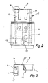
- Figur 3 eine im grösseren Massstab dargestellte Einzelheit "A" in Figur 2,
- Figur 4 eine Seitenansicht einer anderen Ausführungsform der Transportanlage, und
- Figur 5 eine im grösseren Massstab dargestellte Einzelheit "B" in Figur 4.
- In den Figuren 1 und 5 ist die Transportanlage als Teil einer Prozessanlage zur Reinigung und Trocknung von Gegenständen dargestellt.
- Die Transportanlage enthält ein Transportband 1 und ein Transportmittel 2. Das Transportband 1 weist zwei parallele Führungsschienen 4, die miteinander verbunden sind, zwei Endlosbänder 6, die von oben zugänglich auf den Führungsschienen 4 angeordnet sind, und eine Antriebsvorrichtung 7 für die Endlosbänder 6 auf. Es ist eine Hebevorrichtung (8,9) vorgesehen, um das Transportband 1 auf- und abzuverschieben.
- Die Antriebsvorrichtung 7 für die Endlosbänder 6 enthält einen Antriebsmotor 10, eine mit dem Antriebsmotor verbundene Welle 11 und ein Getriebe (nicht dargestellt), das die Welle 11 mit den nicht dargestellten Treibrollen für die Endlosbänder 6 verbindet. Der Motor 10 ist über Stützen 12 an die Schienen 4 befestigt, so dass die Antriebsvorrichtung 7 zusammen mit dem Transportband 1 auf- und abbewegbar ist.
- Der Hebemechanismus 8 enthält zwei Baugruppen, die im Abstand zueinander mit dem Transportband 1 verbunden sind. Jede Baugruppe enthält zwei Führungsstäbe 14, die am Gestell des Gehäuses befestigt sind, zwei Träger 15, die an einem Ende jeweils an einer Führungsschiene 4 befestigt sind, einen Tragbalken 16, der mit den Trägern 15 fest verbunden ist und an den Führungsstäben 14 geführt ist und zwei Führungsvorrichtungen 17, die an den Trägern 15 befestigt sind, um eine Zweipunktführung für jeden träger zu schaffen.
- Die Antriebsvorrichtung 9 umfasst einen Getriebemotor 18, zwei Winkelgetriebe 19, eine Welle 20, die den Motor 18 mit den Winkelgetrieben 19 verbindet, einen Lagerbock 21 für die Welle 20, zwei Gewindespindeln 22, die jeweils an einem Ende an das Winkelgetriebe gekoppelt und am anderen Ende im Gestell des Gehäuses gelagert sind und zwei Muttern 23, die am Tragbalken 16 befestigt ist und mit der Spindel 22 zusammenwirkt.
- Neben den vorstehend beschriebenen Ausführungsformen der Antriebsvorrichtung 7 und der Hebevorrichtung 8,9 sind auch andere Konstruktionen denkbar. So kann die Gewindespindel durch eine Zahnstange ersetzt werden, die über einen Motor auf- und abverschoben wird. Anstelle der Antriebsvorrichtung 7 kann für jedes Endlosband 6 ein Einzelantrieb vorgesehen werden. Bei einer weiteren Ausführungsform können der Hebemechanismus 8 und das Endlosband 6 durch einen einzigen Motor angetrieben werden.
- Das Transportmittel 2 für das Gut 13 enthält einen rahmenförmigen Teil 24 mit seitlich abstehendem Rand 25 und Auflageabschnitten 26, die auf die Endlosbänder 6 auflegbar sind, und Halter 27 für das Gut 13.
- An den Führungsschienen 4 sind nicht dargestellte, den jeweiligen Stationen zugeordnete Schaltelemente angeordnet, die durch den rahmenförmigen Teil 24 betätigt werden. Diese Schaltelemente geben bei Betätigung ein Signal an eine nicht dargestellte Steuereinrichtung ab, um die Transportanlage zu steuern.
- Die in den Figuren 4 und 5 dargestellte Ausführungsform der Transportanlage unterscheidet sich gegenüber der eingangs beschriebenen Anlage durch die tiefer angeordneten Endlosbänder 6 und das konstruktiv daran angepasste Transportmittel 2.
- Die Prozessanlage hat eine Beladestation 31, in der die Transportmittel 2 auf die Endlosbänder 6 auflegbar ist, mehrere Behandlungsstationen 32, die in der Regel ein Bad aufweisen, und eine Entladestation 33, in der die Transportmittel 2 abgenommen werden.
- Nachfolgend wird eine Funktion der Transportanlage beschrieben.
- Zur Aufnahme des Transportmittels 2 in der Beladestation 31 wird das Transportband 1 in die untere Stellung oder Arbeitsstellung abgesenkt. Danach wird das Transportband 1 in die obere Stellung oder Transportstellung angehoben. Erreicht das Transportmittel 2 die erste Behandlungsstation 32, wird durch das entsprechende Schaltelement ein Signal an die Steuereinrichtung abgegeben und das Transportband 2 abgesenkt, so dass das Gut 13 in die erste Behandlungsstation 32 eingebracht wird. Neder vorstehend erwähnten Verschiebung des Transportbandes 2 in die Arbeits- bzw. Transportstellung kann dem Transportband zusätzlich eine Auf- und Abbewegung, die Warenbewegung erteilt werden. In der Entladestation 33 kann das Transportmittel 2 durch Absenken des Transportbandes 1 abgesetzt oder direkt an ein weiteres Transportband abgegeben werden.
Claims (7)
Applications Claiming Priority (2)
| Application Number | Priority Date | Filing Date | Title |
|---|---|---|---|
| CH1712/86 | 1986-04-25 | ||
| CH1712/86A CH670617A5 (de) | 1986-04-25 | 1986-04-25 |
Publications (2)
| Publication Number | Publication Date |
|---|---|
| EP0242830A1 true EP0242830A1 (de) | 1987-10-28 |
| EP0242830B1 EP0242830B1 (de) | 1989-08-16 |
Family
ID=4216837
Family Applications (1)
| Application Number | Title | Priority Date | Filing Date |
|---|---|---|---|
| EP87105750A Expired EP0242830B1 (de) | 1986-04-25 | 1987-04-17 | Transportanlage |
Country Status (4)
| Country | Link |
|---|---|
| US (1) | US4788786A (de) |
| EP (1) | EP0242830B1 (de) |
| CH (1) | CH670617A5 (de) |
| DE (1) | DE3760447D1 (de) |
Cited By (3)
| Publication number | Priority date | Publication date | Assignee | Title |
|---|---|---|---|---|
| EP4640062A1 (de) | 2024-04-25 | 2025-10-29 | University of South Bohemia in Ceske Budejovice | Pflanzenbiostimulator und verfahren zu seiner herstellung |
| EP4640060A1 (de) | 2024-04-25 | 2025-10-29 | University of South Bohemia in Ceske Budejovice | Pflanzenbiostimulator |
| EP4640061A1 (de) | 2024-04-25 | 2025-10-29 | University of South Bohemia in Ceske Budejovice | Pflanzenbiostimulator, der durch kaltes plasma aktiviert wird, und verfahren zu seiner herstellung |
Families Citing this family (19)
| Publication number | Priority date | Publication date | Assignee | Title |
|---|---|---|---|---|
| DE3734267A1 (de) * | 1987-09-14 | 1989-03-23 | Gottlob Schwarzwaelder | Geraet zum halb- bzw. vollautomatischen reinigen von farb- und lackspritzpistolen od. dgl. sowie von farb- und lackverschmutzten gegenstaenden |
| DE9004208U1 (de) * | 1990-04-11 | 1990-06-13 | Groninger & Co Gmbh, 74564 Crailsheim | Einrichtung zur Verarbeitung pharamzeutischer, kosmetischer o.dgl. Medien |
| US5334246A (en) * | 1992-12-23 | 1994-08-02 | Xerox Corporation | Dip coat process material handling system |
| US5313505A (en) * | 1993-04-29 | 1994-05-17 | Salvesen William R | Rod handling apparatus |
| US5749383A (en) * | 1994-08-02 | 1998-05-12 | Grapar Corporation | Non-linear chain belt type conveyor |
| US5803984A (en) * | 1996-02-09 | 1998-09-08 | Danieli Wean, A Division Of Danieli Corporation | Method and apparatus for rinsing steel product |
| DK172873B1 (da) * | 1998-10-07 | 1999-08-23 | Gram As | Apparat samt fremgangsmåde til håndtering af konfektureprodukter |
| US6486415B2 (en) * | 2001-01-16 | 2002-11-26 | International Business Machines Corporation | Compliant layer for encapsulated columns |
| TW558545B (en) * | 2002-04-12 | 2003-10-21 | Taiwan Semiconductor Mfg | Automated material handling system and method |
| US6826849B1 (en) * | 2003-09-26 | 2004-12-07 | Xerox Corporation | Contamination-free photoreceptor drying apparatus |
| US7168549B1 (en) * | 2005-01-11 | 2007-01-30 | Honda Motor Co., Ltd. | Programmable modular pneumatic lift |
| ES2353428T3 (es) * | 2007-04-27 | 2011-03-02 | Nestec S.A. | Llenado de un producto alimenticio dentro de un recipiente sobre un transportador de listones. |
| DE102008036322A1 (de) * | 2008-07-29 | 2010-02-04 | Dürr Systems GmbH | Zwischenlager zum Zwischenlagern von zu lackierenden Gegenständen |
| CN102671883A (zh) * | 2012-05-18 | 2012-09-19 | 上海思恩电子技术(东台)有限公司 | 具有托升推移机构的清洗机 |
| US9132873B1 (en) | 2013-03-14 | 2015-09-15 | Kuka Systems Corporation North America | Flexible conveyance system |
| KR20160023636A (ko) * | 2013-03-14 | 2016-03-03 | 쿠카 시스템즈 노쓰 아메리카 엘엘씨 | 플렉서블 이송 시스템 |
| CN105263832B (zh) * | 2013-03-14 | 2017-12-15 | 库卡系统北美公司 | 灵活运输系统 |
| JP6427783B2 (ja) * | 2014-01-29 | 2018-11-28 | 伊東電機株式会社 | 移載装置及びモータを有する装置の位置決め方法 |
| CN110681620A (zh) * | 2019-10-31 | 2020-01-14 | 安徽鸿海新材料股份有限公司 | 基于覆铜板的清洁干燥装置 |
Citations (1)
| Publication number | Priority date | Publication date | Assignee | Title |
|---|---|---|---|---|
| DE1556171A1 (de) * | 1967-02-24 | 1970-01-22 | Radson Radiotorenfabriek N V | Anlage zur Behandlung von flachen Heizkoerpern |
Family Cites Families (8)
| Publication number | Priority date | Publication date | Assignee | Title |
|---|---|---|---|---|
| US1434859A (en) * | 1919-03-17 | 1922-11-07 | A P Munning & Co | Conveying mechanism |
| US2997191A (en) * | 1958-05-28 | 1961-08-22 | Meaker Company | Processing machine |
| US3022881A (en) * | 1958-12-29 | 1962-02-27 | Hanson Van Winkle Munning Co | Automatic conversion immersing machine |
| US3088610A (en) * | 1960-04-07 | 1963-05-07 | Udylite Corp | Skip and delayed dip mechanism for conveying apparatus |
| US3106927A (en) * | 1962-01-15 | 1963-10-15 | Madwed Albert | Vapor chamber-tank unit |
| US3760927A (en) * | 1971-07-15 | 1973-09-25 | Udylite Corp | Conveying machine with process selector |
| FR2195198A5 (de) * | 1972-08-02 | 1974-03-01 | Cit Alcatel | |
| US4331230A (en) * | 1979-06-25 | 1982-05-25 | Hooker Chemicals & Plastics Corp. | Work rack for conveying apparatus |
-
1986
- 1986-04-25 CH CH1712/86A patent/CH670617A5/de not_active IP Right Cessation
-
1987
- 1987-04-17 EP EP87105750A patent/EP0242830B1/de not_active Expired
- 1987-04-17 DE DE8787105750T patent/DE3760447D1/de not_active Expired
- 1987-04-27 US US07/042,931 patent/US4788786A/en not_active Expired - Fee Related
Patent Citations (1)
| Publication number | Priority date | Publication date | Assignee | Title |
|---|---|---|---|---|
| DE1556171A1 (de) * | 1967-02-24 | 1970-01-22 | Radson Radiotorenfabriek N V | Anlage zur Behandlung von flachen Heizkoerpern |
Cited By (3)
| Publication number | Priority date | Publication date | Assignee | Title |
|---|---|---|---|---|
| EP4640062A1 (de) | 2024-04-25 | 2025-10-29 | University of South Bohemia in Ceske Budejovice | Pflanzenbiostimulator und verfahren zu seiner herstellung |
| EP4640060A1 (de) | 2024-04-25 | 2025-10-29 | University of South Bohemia in Ceske Budejovice | Pflanzenbiostimulator |
| EP4640061A1 (de) | 2024-04-25 | 2025-10-29 | University of South Bohemia in Ceske Budejovice | Pflanzenbiostimulator, der durch kaltes plasma aktiviert wird, und verfahren zu seiner herstellung |
Also Published As
| Publication number | Publication date |
|---|---|
| EP0242830B1 (de) | 1989-08-16 |
| CH670617A5 (de) | 1989-06-30 |
| US4788786A (en) | 1988-12-06 |
| DE3760447D1 (en) | 1989-09-21 |
Similar Documents
| Publication | Publication Date | Title |
|---|---|---|
| EP0242830B1 (de) | Transportanlage | |
| EP0390967A2 (de) | Wässriges saures Bad zur galvanischen Abscheidung von glänzenden und rissfreien Kupferüberzügen und Verwendung dieses Bades | |
| DE2401503C3 (de) | Übergabeeinrichtung für Werkstückträger an den Übergabestationen einer Transferstraße | |
| DE3730434A1 (de) | Automatische loetvorrichtung | |
| DE20202491U1 (de) | Zuführvorrichtung zum Zuführen von Werkstückträgern in Längsrichtung eines Gurtförderers zu einer Bearbeitungsstation | |
| DE3831498C2 (de) | Transportvorrichtung für Kopse | |
| EP0745453A2 (de) | Be- und Entladevorrichtung | |
| EP1106947A1 (de) | Heizvorrichtung | |
| EP0344804B1 (de) | Hängefördersystem | |
| EP0056063A1 (de) | Förderanlage für Werkstücke mit Arbeitsstationen | |
| DE2312902C3 (de) | Einrichtung zur Wärmebehandlung von Werkstücken | |
| EP1021823B1 (de) | Anlage mit transportsystem | |
| DE1506406A1 (de) | Vorrichtung zum Transport von Scheiben,insbesondere Glasscheiben | |
| DE10065709B4 (de) | Beschichtungsanlage | |
| DE3218251C2 (de) | ||
| EP1401611A1 (de) | Montagelinie | |
| EP0105223A1 (de) | Maschine zum Bohren und Einsetzen von Beschlagteilen in plattenförmige Werkstücke | |
| EP0445256B1 (de) | Anlage für das entwässernde pressen einer feststoffmatte | |
| EP0133841B1 (de) | Verfahren und Vorrichtung zum Ausrichten langgestreckter Holzelemente | |
| DE69705184T2 (de) | Einrichtung zum Speichern von Gegenständen auf einer Förderschleife | |
| DE2152392A1 (de) | Geraet zum stapeln oder abstapeln von platten | |
| DE2461530A1 (de) | Foerdervorrichtung fuer langgut, insbesondere fuer schienen | |
| DE10015559A1 (de) | Verfahren und Vorrichtung zum Querausschleusen von Transportgut aus einem Längsfördersystem | |
| DE1431365C3 (de) | Fördereinrichtung für die Behandlung und/oder Kontrolle von Gegenständen, wie Glasgefä&en oder dergleichen | |
| EP0416139A1 (de) | Lineareinheit mit zwei unabhängig voneinander fahrenden Greifern |
Legal Events
| Date | Code | Title | Description |
|---|---|---|---|
| PUAI | Public reference made under article 153(3) epc to a published international application that has entered the european phase |
Free format text: ORIGINAL CODE: 0009012 |
|
| AK | Designated contracting states |
Kind code of ref document: A1 Designated state(s): CH DE FR GB IT LI NL SE |
|
| 17P | Request for examination filed |
Effective date: 19871128 |
|
| 17Q | First examination report despatched |
Effective date: 19890102 |
|
| GRAA | (expected) grant |
Free format text: ORIGINAL CODE: 0009210 |
|
| AK | Designated contracting states |
Kind code of ref document: B1 Designated state(s): CH DE FR GB IT LI NL SE |
|
| GBT | Gb: translation of ep patent filed (gb section 77(6)(a)/1977) | ||
| REF | Corresponds to: |
Ref document number: 3760447 Country of ref document: DE Date of ref document: 19890921 |
|
| ITF | It: translation for a ep patent filed | ||
| ET | Fr: translation filed | ||
| PLBE | No opposition filed within time limit |
Free format text: ORIGINAL CODE: 0009261 |
|
| STAA | Information on the status of an ep patent application or granted ep patent |
Free format text: STATUS: NO OPPOSITION FILED WITHIN TIME LIMIT |
|
| 26N | No opposition filed | ||
| PGFP | Annual fee paid to national office [announced via postgrant information from national office to epo] |
Ref country code: CH Payment date: 19910422 Year of fee payment: 5 |
|
| ITTA | It: last paid annual fee | ||
| PGFP | Annual fee paid to national office [announced via postgrant information from national office to epo] |
Ref country code: GB Payment date: 19920415 Year of fee payment: 6 |
|
| PG25 | Lapsed in a contracting state [announced via postgrant information from national office to epo] |
Ref country code: LI Effective date: 19920430 Ref country code: CH Effective date: 19920430 |
|
| PGFP | Annual fee paid to national office [announced via postgrant information from national office to epo] |
Ref country code: SE Payment date: 19920430 Year of fee payment: 6 Ref country code: NL Payment date: 19920430 Year of fee payment: 6 Ref country code: FR Payment date: 19920430 Year of fee payment: 6 |
|
| PGFP | Annual fee paid to national office [announced via postgrant information from national office to epo] |
Ref country code: DE Payment date: 19920629 Year of fee payment: 6 |
|
| REG | Reference to a national code |
Ref country code: CH Ref legal event code: PUE Owner name: REMO CONSULT AG TRANSFER- HAMO AG |
|
| REG | Reference to a national code |
Ref country code: CH Ref legal event code: PL |
|
| ITPR | It: changes in ownership of a european patent |
Owner name: CESSIONE;REMO CONSULT AG |
|
| REG | Reference to a national code |
Ref country code: GB Ref legal event code: 732E |
|
| REG | Reference to a national code |
Ref country code: FR Ref legal event code: TP |
|
| PG25 | Lapsed in a contracting state [announced via postgrant information from national office to epo] |
Ref country code: GB Effective date: 19930417 |
|
| PG25 | Lapsed in a contracting state [announced via postgrant information from national office to epo] |
Ref country code: SE Effective date: 19930418 |
|
| PG25 | Lapsed in a contracting state [announced via postgrant information from national office to epo] |
Ref country code: NL Effective date: 19931101 |
|
| GBPC | Gb: european patent ceased through non-payment of renewal fee |
Effective date: 19930417 |
|
| NLS | Nl: assignments of ep-patents |
Owner name: REMO CONSULT AG TE ZUG, ZWITSERLAND. |
|
| NLV4 | Nl: lapsed or anulled due to non-payment of the annual fee | ||
| PG25 | Lapsed in a contracting state [announced via postgrant information from national office to epo] |
Ref country code: FR Effective date: 19931229 |
|
| PG25 | Lapsed in a contracting state [announced via postgrant information from national office to epo] |
Ref country code: DE Effective date: 19940101 |
|
| NLS | Nl: assignments of ep-patents |
Owner name: HAMO AG TE PIETERLEN, ZWITSERLAND. |
|
| REG | Reference to a national code |
Ref country code: FR Ref legal event code: ST |
|
| EUG | Se: european patent has lapsed |
Ref document number: 87105750.1 Effective date: 19931110 |
|
| PG25 | Lapsed in a contracting state [announced via postgrant information from national office to epo] |
Ref country code: IT Free format text: LAPSE BECAUSE OF NON-PAYMENT OF DUE FEES;WARNING: LAPSES OF ITALIAN PATENTS WITH EFFECTIVE DATE BEFORE 2007 MAY HAVE OCCURRED AT ANY TIME BEFORE 2007. THE CORRECT EFFECTIVE DATE MAY BE DIFFERENT FROM THE ONE RECORDED. Effective date: 20050417 |