EP0242859A2 - Guide de glissière pour siège de véhicule - Google Patents
Guide de glissière pour siège de véhicule Download PDFInfo
- Publication number
- EP0242859A2 EP0242859A2 EP87105864A EP87105864A EP0242859A2 EP 0242859 A2 EP0242859 A2 EP 0242859A2 EP 87105864 A EP87105864 A EP 87105864A EP 87105864 A EP87105864 A EP 87105864A EP 0242859 A2 EP0242859 A2 EP 0242859A2
- Authority
- EP
- European Patent Office
- Prior art keywords
- clamping
- slide rail
- web
- rail
- rail guide
- Prior art date
- Legal status (The legal status is an assumption and is not a legal conclusion. Google has not performed a legal analysis and makes no representation as to the accuracy of the status listed.)
- Granted
Links
Images


Classifications
-
- B—PERFORMING OPERATIONS; TRANSPORTING
- B60—VEHICLES IN GENERAL
- B60N—SEATS SPECIALLY ADAPTED FOR VEHICLES; VEHICLE PASSENGER ACCOMMODATION NOT OTHERWISE PROVIDED FOR
- B60N2/00—Seats specially adapted for vehicles; Arrangement or mounting of seats in vehicles
- B60N2/24—Seats specially adapted for vehicles; Arrangement or mounting of seats in vehicles for particular purposes or particular vehicles
- B60N2/42—Seats specially adapted for vehicles; Arrangement or mounting of seats in vehicles for particular purposes or particular vehicles the seat constructed to protect the occupant from the effect of abnormal g-forces, e.g. crash or safety seats
- B60N2/43—Safety locks
-
- B—PERFORMING OPERATIONS; TRANSPORTING
- B60—VEHICLES IN GENERAL
- B60N—SEATS SPECIALLY ADAPTED FOR VEHICLES; VEHICLE PASSENGER ACCOMMODATION NOT OTHERWISE PROVIDED FOR
- B60N2/00—Seats specially adapted for vehicles; Arrangement or mounting of seats in vehicles
- B60N2/02—Seats specially adapted for vehicles; Arrangement or mounting of seats in vehicles the seat or part thereof being movable, e.g. adjustable
- B60N2/04—Seats specially adapted for vehicles; Arrangement or mounting of seats in vehicles the seat or part thereof being movable, e.g. adjustable the whole seat being movable
- B60N2/06—Seats specially adapted for vehicles; Arrangement or mounting of seats in vehicles the seat or part thereof being movable, e.g. adjustable the whole seat being movable slidable
- B60N2/07—Slide construction
- B60N2/0702—Slide construction characterised by its cross-section
- B60N2/0715—C or U-shaped
-
- B—PERFORMING OPERATIONS; TRANSPORTING
- B60—VEHICLES IN GENERAL
- B60N—SEATS SPECIALLY ADAPTED FOR VEHICLES; VEHICLE PASSENGER ACCOMMODATION NOT OTHERWISE PROVIDED FOR
- B60N2/00—Seats specially adapted for vehicles; Arrangement or mounting of seats in vehicles
- B60N2/02—Seats specially adapted for vehicles; Arrangement or mounting of seats in vehicles the seat or part thereof being movable, e.g. adjustable
- B60N2/04—Seats specially adapted for vehicles; Arrangement or mounting of seats in vehicles the seat or part thereof being movable, e.g. adjustable the whole seat being movable
- B60N2/06—Seats specially adapted for vehicles; Arrangement or mounting of seats in vehicles the seat or part thereof being movable, e.g. adjustable the whole seat being movable slidable
- B60N2/08—Seats specially adapted for vehicles; Arrangement or mounting of seats in vehicles the seat or part thereof being movable, e.g. adjustable the whole seat being movable slidable characterised by the locking device
- B60N2/0812—Location of the latch
- B60N2/0825—Location of the latch outside the rail
-
- B—PERFORMING OPERATIONS; TRANSPORTING
- B60—VEHICLES IN GENERAL
- B60N—SEATS SPECIALLY ADAPTED FOR VEHICLES; VEHICLE PASSENGER ACCOMMODATION NOT OTHERWISE PROVIDED FOR
- B60N2/00—Seats specially adapted for vehicles; Arrangement or mounting of seats in vehicles
- B60N2/02—Seats specially adapted for vehicles; Arrangement or mounting of seats in vehicles the seat or part thereof being movable, e.g. adjustable
- B60N2/04—Seats specially adapted for vehicles; Arrangement or mounting of seats in vehicles the seat or part thereof being movable, e.g. adjustable the whole seat being movable
- B60N2/06—Seats specially adapted for vehicles; Arrangement or mounting of seats in vehicles the seat or part thereof being movable, e.g. adjustable the whole seat being movable slidable
- B60N2/08—Seats specially adapted for vehicles; Arrangement or mounting of seats in vehicles the seat or part thereof being movable, e.g. adjustable the whole seat being movable slidable characterised by the locking device
- B60N2/0831—Movement of the latch
- B60N2/0862—Movement of the latch sliding
- B60N2/0868—Movement of the latch sliding in a transversal direction
-
- B—PERFORMING OPERATIONS; TRANSPORTING
- B60—VEHICLES IN GENERAL
- B60N—SEATS SPECIALLY ADAPTED FOR VEHICLES; VEHICLE PASSENGER ACCOMMODATION NOT OTHERWISE PROVIDED FOR
- B60N2/00—Seats specially adapted for vehicles; Arrangement or mounting of seats in vehicles
- B60N2/02—Seats specially adapted for vehicles; Arrangement or mounting of seats in vehicles the seat or part thereof being movable, e.g. adjustable
- B60N2/04—Seats specially adapted for vehicles; Arrangement or mounting of seats in vehicles the seat or part thereof being movable, e.g. adjustable the whole seat being movable
- B60N2/06—Seats specially adapted for vehicles; Arrangement or mounting of seats in vehicles the seat or part thereof being movable, e.g. adjustable the whole seat being movable slidable
- B60N2/08—Seats specially adapted for vehicles; Arrangement or mounting of seats in vehicles the seat or part thereof being movable, e.g. adjustable the whole seat being movable slidable characterised by the locking device
- B60N2/0831—Movement of the latch
- B60N2/0862—Movement of the latch sliding
- B60N2/0875—Movement of the latch sliding in a vertical direction
Definitions
- the invention relates to a slide rail guide for vehicle seats, in particular for passenger cars, which consists of an outer rail (3) fixed to the vehicle floor with an inner rail longitudinally displaceable therein and associated with the seat part, and in addition to an adjusting device with which the position of the rails relative to one another can be set and locked, has an acceleration-sensitive blocking device that creates a clamping block between the outer and inner rails.
- the acceleration-sensitive blocking device consists of a pendulum-like pivotable locking part which is held on a rail and mind has at least one gripping edge interacting with the other rail.
- the outer and inner rails of slide rail guides are blocked against one another in the event of accelerations suddenly attacking the vehicle (impact in the event of an accident), thereby relieving the load on the adjusting device for the rail guide system.
- the forces acting on the slide rails at the time of the accident are particularly high if the belts engage the seat itself and not the vehicle compartment to restrain the person on the seat. This has the consequence that the locking part with the gripping edge penetrates so far into the wall of the corresponding rail that it cannot be released again from the blocking position.
- the object of the invention is now the load transferring blocking device within a slide rail guide for vehicle seats so that the blocking device unlocks as soon as no acceleration force acts.
- the invention can thus be arranged with very little space in the inner protected area of the outer rail clamping or locking members that are held by a sensor spring in the unblocked rest position and in the working position, grip the web in the inner rail over a large area.
- This large-area load transfer between the clamping elements and the web prevents deformations of the webs, which complicate, even prevent, the loosening of the clamping elements.
- the blocking elements are arranged in mirror image in duplicate, so that the forces emanating from the accelerated masses can be absorbed in both directions, ie in the event of a frontal and rear impact.
- electrical adjustment devices for the slide rails this version enables the use of light and simply designed drive elements (e.g. no coated racks on the web).
- mechanical Adjustment brings this embodiment the advantage of stepless positioning and easy locking.
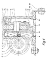
- the slide rail guide shown in FIG. 1 consists of an inner rail 2 designed as a U-shaped rod, which is guided via balls 50 in an outer rail 3.
- the connection of this tour with one is not
- the seat shown is carried out both at the front and at the rear of the seat via struts 45 which are fastened to the inner rail 2 of the right and left rail guides with bolts 27.
- the outer rail 3 is connected via claws 43 and screws 7 to the floor panel 41 of a passenger car.
- the transmission of horizontal forces ven the outer rails 3 in the bottom plate 41 takes place via slugs 40 which engage in holes 16 in the bottom 23 of the outer rail 3.
- the vertical forces acting on the outer rail 3 are derived from the claws 43 into the base plate 41.
- the outer rail 3 has a substantially C-shaped cross section and projects above with flanges 22 over the inner rail 2.
- the free ends of the flanges 22 have bevels 44 which cooperate with corresponding bevels 44 'on the inner rail 2 and secure the connection between the outer 3 and inner rail 2 when 45 tensile forces act on the struts.
- the inner rail 2 has, on one of its legs 4, a web 5 which extends in the axial direction and which is arranged centrally from the inner space of the outer rail 3.
- Blocking devices 6 held on the outer rail 3 act on both sides of this web 5, which are automatically activated in the event of sudden changes in acceleration and exert a braking effect on the web 5, as a result of which the inner rail 2 is blocked in the outer rail 3 and the forces acting on the inner rail are applied to the Outer rail 3 are transmitted without loading the adjusting device of the slide rail guide.
- a toothing 7 is also provided on the web 5, with which a worm 8 held on the outer rail 3 meshes and is driven by a flexible shaft.
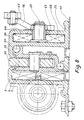
- FIG. 2 shows a simple, effective and inexpensive blocking device 6 which is inserted into the slide rail guide according to FIG. 1 and consists of only a few parts.
- a clamping wedge 12 equipped with a sensor mass 13 is slidably supported within a housing 10 with guide bevels 14 and 14 ⁇ by a sensor spring 11.
- the housing 10 is fastened with screws 51 on the outer rail 3.
- clamping wedges 12 act on both sides of the web 5, this is not deformed when forces as large as occur, so that the clamping connection between the clamping wedges 12 and the web 5 is released from the sensor springs 10 again is as soon as no acceleration forces act on the clamping pieces 12.
- This deblocking can be supported by the fact that the sliding surface between the housing 10 and the clamping wedge 12 with a low-friction surface, for. B. are provided with a PTFE coating.
- the clamping surface of the clamping wedge 12 which cooperates with the web 5, on the other hand, should have a large surface friction.
- surface-protecting friction agents should be used, such as a rubber layer 20 (Fig. 2 magnification X3) or a brake pad 21 (Fig. 2 magnification X4).
- the response lies Threshold of the blocking device at about 5 g (acceleration in the event of an accident)
- aggressive surfaces can also be used, such as a roughened surface 18 (FIG. 2 enlargement X1) or even a sawtooth-like surface 19 (FIG. 2 enlargement X2).
- the horizontal forces that arise in the event of a blockage are conducted into a bore in the outer rail 3 via a pin 15.
- the vertical forces are supported at the top by the flange 22 and at the bottom by the bottom 23 of the outer rail.
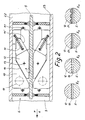
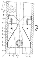
- the blocking device 6 shown in FIG. 3 for a slide rail guide according to FIG. 1 has the on both sides of the web 5 Inner rail each have a clamping body 24, which are guided in parallel by means of two pressure levers 25.
- the sensor springs 11 hold the clamp body 24 against a stop 26 in free position.
- the clamping bodies 24 deflect toward the web 5 and effect the blocking.
- the relatively high spreading forces which are introduced into the wall of the outer rail 3 via bolts 27 can be absorbed by an additional reinforcing plate 28.
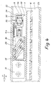
- FIG. 4 shows a blocking device which cooperates with the rack 7 on the web 5, via which the longitudinal adjustment of the inner rail relative to the outer rail 3 takes place.
- a locking body 30 with locking teeth 38 which can be snapped into the rack 7, mounted.
- a strong sensor spring 11b holds the blocking body 30 in the free position.
- the locking body 30 is assigned a sensor 33 which is set more sensitively than the system of locking body 30 and sensor spring via a sensor spring 11 11b.
- the sensor spring 11 holds a spherical sensor mass 34 in the housing 35 with the aid of a lever 36 articulated on a housing 35.
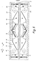
- the blocking device according to FIG. 2 is arranged in mirror image in duplicate, as shown in FIG. 5, the inertial forces of the masses of the seating system can be caused by the front and rear impact of the vehicle blocked slide rail guide are derived in the floor panel of the vehicle. 2 offers the advantage that no forces act on the drive for longitudinal adjustment of the vehicle seat in the event of an accident, so that the drive system can be designed easily and inexpensively.
- FIGS. 1 to 5 only concerned slide rail guides with electrical seat adjustment.
- FIG. 6 a blocking device according to the invention for a seat with mechanical longitudinal adjustment is described, which is designed analogously to the device shown in FIG. 2.
- Two clamping wedges 12b are held in a permanent blocking position with the web 5 by a compression spring 48. If the position of the inner to outer rail 3 and thus the seat in the vehicle is to be changed, the clamping wedges 12b must be released from the blocking position, which is done with a lever 47, when actuated with the aid of the guide lever 29b, the clamping wedges 12b against the force of the Compression spring 48 are moved.
- the clamping wedge 12 provided below the web 5 is designed to be acceleration-sensitive, as has been described above in connection with FIG. 2.
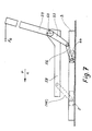
- FIG. 7 to 9 show a vehicle seat 58 with details of its slide rail guide, on the back 59 of which straps (not shown) of a passenger restraint system are attached.
- an acceleration a acts in the direction of arrow v, so that the belt force F G acts on the upper edge of the backrest 59 and adjusts a cantilever arm 57 projecting downward from the backrest 59 in the opposite direction.
- an acceleration-sensitive blocking device 6b with which the cantilever arm 57 is connected via a steering lever 56 and which is arranged so as to be linearly displaceable in a secondary chamber 54 of the outer rail 3 (FIG. 8).
- the blocking device 6b (FIG. 9) has a sliding body 61 which is guided over low-sliding surfaces 64 in the secondary chamber 54 and has two clamping wedges 12c slidably mounted on two guide slopes 14 against the force of sensor springs 11. These wedges 12c speak of acceleration Changes in the same way as the clamping wedges 12 of the blocking device according to FIG. 2, ie the clamping wedges 12c move to the left in the event of a frontal impact against the force of the sensor springs 11. They slide along the guide bevels 14 and abut with the clamping surfaces 17 against the walls 22 and 23 of the outer rail 3, as a result of which the blocking device 6b locks and the backrest 59 is held in the current position.
Landscapes
- Engineering & Computer Science (AREA)
- Aviation & Aerospace Engineering (AREA)
- Transportation (AREA)
- Mechanical Engineering (AREA)
- Seats For Vehicles (AREA)
Applications Claiming Priority (2)
| Application Number | Priority Date | Filing Date | Title |
|---|---|---|---|
| DE19863613832 DE3613832A1 (de) | 1986-04-24 | 1986-04-24 | Lineares schienenfuehrungssystem mit beschleunigungssensitiver blockiereinrichtung |
| DE3613832 | 1986-04-24 |
Publications (3)
| Publication Number | Publication Date |
|---|---|
| EP0242859A2 true EP0242859A2 (fr) | 1987-10-28 |
| EP0242859A3 EP0242859A3 (en) | 1988-10-12 |
| EP0242859B1 EP0242859B1 (fr) | 1991-12-18 |
Family
ID=6299406
Family Applications (1)
| Application Number | Title | Priority Date | Filing Date |
|---|---|---|---|
| EP87105864A Expired - Lifetime EP0242859B1 (fr) | 1986-04-24 | 1987-04-22 | Guide de glissière pour siège de véhicule |
Country Status (3)
| Country | Link |
|---|---|
| EP (1) | EP0242859B1 (fr) |
| DE (2) | DE3613832A1 (fr) |
| ES (1) | ES2027650T3 (fr) |
Cited By (6)
| Publication number | Priority date | Publication date | Assignee | Title |
|---|---|---|---|---|
| EP0316789A3 (en) * | 1987-11-14 | 1990-04-11 | P.A. Rentrop, Hubbert & Wagner Fahrzeugausstattungen Gmbh & Co. Kg | Adjustable power transmission element using inertia-sensitive blocking |
| EP0459173A3 (fr) * | 1990-06-01 | 1991-12-11 | Audi Ag | Dispositif pour connecter un siège de véhicule à des éléments de sol d'un véhicule |
| WO2014198694A1 (fr) * | 2013-06-14 | 2014-12-18 | Johnson Controls Gmbh | Substructure de siège de véhicule munie d'un dispositif de réglage induit par un accident |
| WO2019011667A1 (fr) * | 2017-07-14 | 2019-01-17 | Adient Engineering and IP GmbH | Dispositif de réglage longitudinal pour siège de véhicule et siège de véhicule |
| US11420543B2 (en) * | 2018-12-20 | 2022-08-23 | Hyundai Transys Inc. | Seat track mechanism for vehicle |
| US12122265B2 (en) | 2020-05-14 | 2024-10-22 | Lear Corporation | Track assembly |
Families Citing this family (9)
| Publication number | Priority date | Publication date | Assignee | Title |
|---|---|---|---|---|
| DE4123102A1 (de) * | 1991-07-09 | 1993-01-14 | Brose Fahrzeugteile | Rueckhaltevorrichtung fuer fahrzeugsitze |
| DE19922626B4 (de) * | 1999-05-18 | 2005-11-17 | Keiper Gmbh & Co.Kg | Längseinstellvorrichtung für einen Fahrzeugsitz |
| DE10235086B4 (de) | 2002-07-31 | 2009-10-29 | Johnson Controls Gmbh | Sicherheitseinrichtung für Fahrzeugsitze |
| FR2882005B1 (fr) * | 2005-02-14 | 2009-01-23 | Faurecia Sieges Automobile | Glissiere pour siege de vehicule dotee d'un dispositif de securite, et siege comportant une telle glissiere |
| DE102006055267B4 (de) * | 2006-11-23 | 2017-09-07 | Faurecia Autositze Gmbh | Fahrzeugsitz mit einer Längsverstellvorrichtung |
| DE202007006446U1 (de) * | 2007-05-05 | 2008-09-18 | Brose Fahrzeugteile Gmbh & Co. Kommanditgesellschaft, Coburg | Arretiervorrichtung für einen Kraftfahrzeugsitz |
| DE102011008803A1 (de) * | 2010-12-22 | 2012-06-28 | BÖCO Böddecker & Co. GmbH & Co. KG | Vorrichtung zur Halterung einer Lehne eines Fahrzeugsitzes |
| DE102020122698A1 (de) | 2020-08-31 | 2022-03-03 | Sitech Sitztechnik Gmbh | Elektrische Ver- und Entriegelungseinrichtung einer Sitzschiene |
| FR3124130B1 (fr) | 2021-06-21 | 2025-07-11 | Faurecia Sieges Dautomobile | système de verrouillage d’une glissière à réglage continu |
Family Cites Families (7)
| Publication number | Priority date | Publication date | Assignee | Title |
|---|---|---|---|---|
| DE188097C (fr) * | ||||
| FR728326A (fr) * | 1931-12-16 | 1932-07-04 | Parachute pour ascenseur ou monte-charge | |
| DE2659311A1 (de) * | 1976-12-29 | 1978-07-06 | Keiper Automobiltechnik Gmbh | Laengsverschiebbarer und in waehlbaren laengslagen feststellbarer, insbesondere in kraftfahrzeugen anzuordnender sitz |
| DE7700316U1 (de) * | 1977-01-07 | 1978-10-26 | C. Rob. Hammerstein Gmbh, 5650 Solingen | Sperre fuer gleitschienenfuehrungen fuer fahrzeugsitze |
| DE3132235A1 (de) * | 1981-08-14 | 1983-11-10 | Brose Fahrzeugteile GmbH & Co KG, 8630 Coburg | Sitzverstellung, insbesondere fuer einen kraftfahrzeugsitz |
| DE3239682C2 (de) * | 1982-10-27 | 1993-09-30 | Keiper Automobiltechnik Gmbh | Sitzlängsverstelleinrichtung |
| DE8409246U1 (de) * | 1984-03-26 | 1984-09-20 | Linde & Wiemann GmbH KG, 6340 Dillenburg | Fuehrungsschiene fuer kraftfahrzeugsitze |
-
1986
- 1986-04-24 DE DE19863613832 patent/DE3613832A1/de not_active Ceased
-
1987
- 1987-04-22 ES ES198787105864T patent/ES2027650T3/es not_active Expired - Lifetime
- 1987-04-22 DE DE8787105864T patent/DE3775258D1/de not_active Expired - Fee Related
- 1987-04-22 EP EP87105864A patent/EP0242859B1/fr not_active Expired - Lifetime
Cited By (8)
| Publication number | Priority date | Publication date | Assignee | Title |
|---|---|---|---|---|
| EP0316789A3 (en) * | 1987-11-14 | 1990-04-11 | P.A. Rentrop, Hubbert & Wagner Fahrzeugausstattungen Gmbh & Co. Kg | Adjustable power transmission element using inertia-sensitive blocking |
| EP0459173A3 (fr) * | 1990-06-01 | 1991-12-11 | Audi Ag | Dispositif pour connecter un siège de véhicule à des éléments de sol d'un véhicule |
| WO2014198694A1 (fr) * | 2013-06-14 | 2014-12-18 | Johnson Controls Gmbh | Substructure de siège de véhicule munie d'un dispositif de réglage induit par un accident |
| WO2019011667A1 (fr) * | 2017-07-14 | 2019-01-17 | Adient Engineering and IP GmbH | Dispositif de réglage longitudinal pour siège de véhicule et siège de véhicule |
| CN110914104A (zh) * | 2017-07-14 | 2020-03-24 | 安道拓工程技术知识产权有限公司 | 用于车辆座椅的纵向调节器和车辆座椅 |
| US11065986B2 (en) | 2017-07-14 | 2021-07-20 | Adient Engineering and IP GmbH | Longitudinal adjuster for a vehicle seat, and vehicle seat |
| US11420543B2 (en) * | 2018-12-20 | 2022-08-23 | Hyundai Transys Inc. | Seat track mechanism for vehicle |
| US12122265B2 (en) | 2020-05-14 | 2024-10-22 | Lear Corporation | Track assembly |
Also Published As
| Publication number | Publication date |
|---|---|
| EP0242859A3 (en) | 1988-10-12 |
| ES2027650T3 (es) | 1992-06-16 |
| DE3775258D1 (de) | 1992-01-30 |
| DE3613832A1 (de) | 1987-10-29 |
| EP0242859B1 (fr) | 1991-12-18 |
Similar Documents
| Publication | Publication Date | Title |
|---|---|---|
| DE4201354C2 (de) | Schienenanordnung für einen Fahrzeugsitz | |
| DE19911786C2 (de) | Crashverriegelung für eine Verstelleinrichtung eines Kraftfahrzeugsitzes | |
| EP0242859A2 (fr) | Guide de glissière pour siège de véhicule | |
| EP0305765A2 (fr) | Détecteur d'accélération pour systèmes de sécurité et/ou systèmes de ceintures de sécurité de voiture | |
| DE102019205122B4 (de) | Aufprallschutz und damit ausgestatteter Kindersitz | |
| DE2028138A1 (de) | Vorrichtung zum gegenseitigen Verriegeln zweier gegeneinander verschiebbarer Bauele mente | |
| DE3237629A1 (de) | Verankerungsvorrichtung fuer einen schultergurt | |
| DE102018113177B4 (de) | Längseinsteller und Fahrzeugsitz | |
| DE10138248C1 (de) | Aktive Kopfstütze mit Verriegelungseinrichtung | |
| DE102013010705B4 (de) | Kopfstütze, die in x-richtung in eine sicherheitsstellung und eine komfortstellung überführbar ist | |
| DE10201092A1 (de) | Sicherheitseinrichtung für Fahrzeugsitzbänke | |
| DE2856437C2 (fr) | ||
| DE10008524B4 (de) | Kraftfahrzeugsitz mit einer klappbaren Rückenlehne und einer höhenverstellbaren Kopfstütze | |
| DE10033297B4 (de) | Fahrpedalmodul | |
| DE102021102604A1 (de) | Fahrzeugsitzkonsole und Fahrzeugsitz | |
| EP1126991A1 (fr) | Dispositif de securite pour banquettes de vehicules | |
| EP0943507B1 (fr) | Rétracteur de sangle pour un système de ceinture de sécurité de véhicule | |
| DE29700549U1 (de) | Verstellvorrichtung für einen Umlenkbeschlag eines Fahrzeug-Sicherheitsgurtsystems | |
| DE3737974C2 (fr) | ||
| EP0686526B1 (fr) | Détecteur pour déclencher un allumage en cas de forte décélération d'un véhicule | |
| DE102017213591B4 (de) | Fahrzeugsitz für ein Kraftfahrzeug | |
| DE3306434C2 (fr) | ||
| DE102021112554A1 (de) | Fahrzeugsitz, umfassend ein Kraftrückgewinnungssystem im Fall eines Aufpralls | |
| DE29908320U1 (de) | Höhenverstellvorrichtung für Gurtbeschlag | |
| DE19539439C2 (de) | Klemmvorrichtung |
Legal Events
| Date | Code | Title | Description |
|---|---|---|---|
| PUAI | Public reference made under article 153(3) epc to a published international application that has entered the european phase |
Free format text: ORIGINAL CODE: 0009012 |
|
| AK | Designated contracting states |
Kind code of ref document: A2 Designated state(s): DE ES FR GB IT SE |
|
| PUAL | Search report despatched |
Free format text: ORIGINAL CODE: 0009013 |
|
| AK | Designated contracting states |
Kind code of ref document: A3 Designated state(s): DE ES FR GB IT SE |
|
| 17P | Request for examination filed |
Effective date: 19881104 |
|
| RAP1 | Party data changed (applicant data changed or rights of an application transferred) |
Owner name: P.A. RENTROP, HUBBERT & WAGNER FAHRZEUGAUSSTATTUNG |
|
| RIN1 | Information on inventor provided before grant (corrected) |
Inventor name: ERNST, HANS HELLMUT |
|
| 17Q | First examination report despatched |
Effective date: 19891025 |
|
| GRAA | (expected) grant |
Free format text: ORIGINAL CODE: 0009210 |
|
| AK | Designated contracting states |
Kind code of ref document: B1 Designated state(s): DE ES FR GB IT SE |
|
| GBT | Gb: translation of ep patent filed (gb section 77(6)(a)/1977) | ||
| REF | Corresponds to: |
Ref document number: 3775258 Country of ref document: DE Date of ref document: 19920130 |
|
| ET | Fr: translation filed | ||
| ITF | It: translation for a ep patent filed | ||
| REG | Reference to a national code |
Ref country code: ES Ref legal event code: FG2A Ref document number: 2027650 Country of ref document: ES Kind code of ref document: T3 |
|
| PLBE | No opposition filed within time limit |
Free format text: ORIGINAL CODE: 0009261 |
|
| STAA | Information on the status of an ep patent application or granted ep patent |
Free format text: STATUS: NO OPPOSITION FILED WITHIN TIME LIMIT |
|
| 26N | No opposition filed | ||
| PGFP | Annual fee paid to national office [announced via postgrant information from national office to epo] |
Ref country code: SE Payment date: 19930309 Year of fee payment: 7 |
|
| PGFP | Annual fee paid to national office [announced via postgrant information from national office to epo] |
Ref country code: GB Payment date: 19930414 Year of fee payment: 7 |
|
| PGFP | Annual fee paid to national office [announced via postgrant information from national office to epo] |
Ref country code: FR Payment date: 19930428 Year of fee payment: 7 |
|
| PGFP | Annual fee paid to national office [announced via postgrant information from national office to epo] |
Ref country code: ES Payment date: 19940408 Year of fee payment: 8 |
|
| PG25 | Lapsed in a contracting state [announced via postgrant information from national office to epo] |
Ref country code: GB Effective date: 19940422 |
|
| PG25 | Lapsed in a contracting state [announced via postgrant information from national office to epo] |
Ref country code: SE Effective date: 19940423 |
|
| GBPC | Gb: european patent ceased through non-payment of renewal fee |
Effective date: 19940422 |
|
| PG25 | Lapsed in a contracting state [announced via postgrant information from national office to epo] |
Ref country code: FR Effective date: 19941229 |
|
| EUG | Se: european patent has lapsed |
Ref document number: 87105864.0 Effective date: 19941110 |
|
| REG | Reference to a national code |
Ref country code: FR Ref legal event code: ST |
|
| PG25 | Lapsed in a contracting state [announced via postgrant information from national office to epo] |
Ref country code: ES Free format text: LAPSE BECAUSE OF NON-PAYMENT OF DUE FEES Effective date: 19950424 |
|
| PGFP | Annual fee paid to national office [announced via postgrant information from national office to epo] |
Ref country code: DE Payment date: 19960326 Year of fee payment: 10 |
|
| PG25 | Lapsed in a contracting state [announced via postgrant information from national office to epo] |
Ref country code: DE Free format text: LAPSE BECAUSE OF NON-PAYMENT OF DUE FEES Effective date: 19980101 |
|
| REG | Reference to a national code |
Ref country code: ES Ref legal event code: FD2A Effective date: 19990201 |
|
| PG25 | Lapsed in a contracting state [announced via postgrant information from national office to epo] |
Ref country code: IT Free format text: LAPSE BECAUSE OF NON-PAYMENT OF DUE FEES;WARNING: LAPSES OF ITALIAN PATENTS WITH EFFECTIVE DATE BEFORE 2007 MAY HAVE OCCURRED AT ANY TIME BEFORE 2007. THE CORRECT EFFECTIVE DATE MAY BE DIFFERENT FROM THE ONE RECORDED. Effective date: 20050422 |