EP0242922A2 - Hochauflösendes Fernsehübertragungssystem - Google Patents
Hochauflösendes Fernsehübertragungssystem Download PDFInfo
- Publication number
- EP0242922A2 EP0242922A2 EP87200722A EP87200722A EP0242922A2 EP 0242922 A2 EP0242922 A2 EP 0242922A2 EP 87200722 A EP87200722 A EP 87200722A EP 87200722 A EP87200722 A EP 87200722A EP 0242922 A2 EP0242922 A2 EP 0242922A2
- Authority
- EP
- European Patent Office
- Prior art keywords
- picture
- scanning lines
- signal
- forming
- coupled
- Prior art date
- Legal status (The legal status is an assumption and is not a legal conclusion. Google has not performed a legal analysis and makes no representation as to the accuracy of the status listed.)
- Withdrawn
Links
- 230000005540 biological transmission Effects 0.000 title claims abstract description 81
- 238000000034 method Methods 0.000 claims abstract description 11
- 230000006835 compression Effects 0.000 claims description 17
- 238000007906 compression Methods 0.000 claims description 17
- 239000011159 matrix material Substances 0.000 claims description 9
- 230000005236 sound signal Effects 0.000 claims description 6
- 239000000969 carrier Substances 0.000 claims description 4
- 230000000875 corresponding effect Effects 0.000 claims 5
- 230000009977 dual effect Effects 0.000 description 7
- 230000015654 memory Effects 0.000 description 7
- 238000010586 diagram Methods 0.000 description 6
- 238000011045 prefiltration Methods 0.000 description 4
- 238000001228 spectrum Methods 0.000 description 3
- 239000000284 extract Substances 0.000 description 2
- 238000001914 filtration Methods 0.000 description 2
- 208000007542 Paresis Diseases 0.000 description 1
- 230000004075 alteration Effects 0.000 description 1
- 238000006243 chemical reaction Methods 0.000 description 1
- 239000002131 composite material Substances 0.000 description 1
- 230000007423 decrease Effects 0.000 description 1
- 230000001934 delay Effects 0.000 description 1
- 230000003111 delayed effect Effects 0.000 description 1
- 238000012986 modification Methods 0.000 description 1
- 230000004048 modification Effects 0.000 description 1
- 208000012318 pareses Diseases 0.000 description 1
- 230000004044 response Effects 0.000 description 1
- 230000001702 transmitter Effects 0.000 description 1
Images


Classifications
-
- H—ELECTRICITY
- H04—ELECTRIC COMMUNICATION TECHNIQUE
- H04N—PICTORIAL COMMUNICATION, e.g. TELEVISION
- H04N7/00—Television systems
- H04N7/08—Systems for the simultaneous or sequential transmission of more than one television signal, e.g. additional information signals, the signals occupying wholly or partially the same frequency band, e.g. by time division
- H04N7/083—Systems for the simultaneous or sequential transmission of more than one television signal, e.g. additional information signals, the signals occupying wholly or partially the same frequency band, e.g. by time division with signal insertion during the vertical and the horizontal blanking interval, e.g. MAC data signals
-
- H—ELECTRICITY
- H04—ELECTRIC COMMUNICATION TECHNIQUE
- H04N—PICTORIAL COMMUNICATION, e.g. TELEVISION
- H04N11/00—Colour television systems
- H04N11/24—High-definition television systems
- H04N11/26—High-definition television systems involving two-channel transmission
-
- H—ELECTRICITY
- H04—ELECTRIC COMMUNICATION TECHNIQUE
- H04N—PICTORIAL COMMUNICATION, e.g. TELEVISION
- H04N7/00—Television systems
- H04N7/04—Systems for the transmission of one television signal, i.e. both picture and sound, by a single carrier
Definitions
- the invention relates to a method of and a system for transmitting a high-definition television signal containing picture information which, on display, forms first picture frames at a rate of 2n frames per second, where n is a standard number of picture frames per second formed by the picture information in a standard television signal, and having a width which is wider than that of a standard aspect ratio picture frame, said high-definition television signal having a bandwidth greater than that of a standard television signal, each of said first picture frames including a single field having m sequentially scanned scanning lines, where m is a standard number of interlaced scanning lines in each picture frame formed by the picture information in said standard television signal in which said scanning lines are arranged in two interlaced fields.
- some systems propose increasing the width of the displayed picture by correspondingly increasing the aspect ration by 33.3%, from a standard aspect ration of 4:3 to 5-1/3:3, combined with increasing the number of scanning lines in each picture frame and increasing the bandwidth of the luminance in the television signal by at least two times.
- Each of these systems include at least one frame store at the receiver capable of storing at least one picture frame of the television signal which significantly adds to the cost of the receiver.
- An object of the present invention is to provide a television system for transmitting a high-definition television signal having picture information forming, on display, picture frames having an aspect ratio which is wider than that of a standard aspect ration picture frame.
- Another object of the present invention is to provide a television system for transmitting a high-definition television signal which does not require a frame store.
- a method of transmitting a high-definition television signal as set forth in the opening paragraph, characterized in that said method comprises: converting said high-definition television signal into a first transmission signal compatibel with standard television receivers and containing first picture informat ion derived from the picture information in said high-definition on television signal forming substantially a first half of the scanning lines in said first picture frames, said first picture information forming, on display, second picture frames each of which having m interlaced scanning lines in two fields and corresponding to a selected portion of said first picture frames having said standard aspect ratio; converting said high-definition television signal into a second transmission signal containing second picture information derived from the picture information in said high-definition television signal forming substantially a second half of the scanning lines in said first picture frames and forming a portion of said first picture frames not included in said selected portion in said second picture frames, said second picture information forming, on display, third picture frames each of which having m scanning lines in two fields,
- a television transmitter for transmitting a high-definition television signal as set forth in the opening paragraph, characterized in that said television transmitter comprises: means for converting said high-definition television signal into a first transmission signal compatible with standard television receivers and containing first picture information derived from the picture information in said high-definition television signal forming substantially a first half of the scanning lines in said first picture frames, said first picture information forming, on display, second picture frames each of which having m interlaced scanning lines in two fields and corresponding to a selected portion of said first picture frames having said standard aspect ratio; means for converting said high-definition television signal into a second transmission signal containing second picture information derived from the picture information in said high-definition television signal forming substantially a second half of the scanning lines in said first picture frames and forming a portion of said first picture frames not included in said selected portion in said second picture frames, said second picture information forming,
- a television receiver for simultaneously receiving said first and second transmission signals transmitted by said television transmitter, characterized in that said television receiver comprises: means for receiving said first and second transmission signals; first means for converting said first transmission signal into a first picture signal forming substantially a first half of the scanning lines in a display picture frame and having said standard aspect ratio corresponding to said selected portion; second means for converting said second transmission signal into a second picture signal forming substantially a second half of the scanning lines in said display picture frame and having said standard aspect ratio corresponding to said portion not included in said selected portion; and means for combining said first and second picture signals to form a television signal which substantially corresponds to said high-definition television signal.
- the invention recognizes that one of the factors which significantly limited the perceived vertical resolution of standard television signals is that the picture frames formed tereby include two interlaced fields of scanning lines.
- the subject invention greatly increases this perceived vertical resolution and consequently decreases scan line visibility by sequentially scanning the lines in each picture frame formed by the high-definition television signal and presenting these picture frames at twice the frame rate of a standard television signal.
- a television transmission system in accordance with the invention is shown in Figure 1.
- a television camera 1 is adapted to generate a high-definition television signal and contains circuitry for converting the signal into a first and a second transmission signal of which at least the first transmission signal conforms with, for example, the NTSC television standard.
- the first television signal is then applied to a first transmitter 3 with its associated transmission channel, shown here as antenna 4, while the second transmission signal is simultaneously applied to a second transmitter 5 with its associated transmission channel, shown here as antenna 6.
- the first transmission signal is compatible with standard television receiver 8 having a single tuner. Hower, with a high-definition television receiver 9, both transmission signals may be simultaneously received, respectively, by the two tuners therein and thereupon reconverted into the high-definition television signal.
- the subject television transmission system generates a high-definition television signal for forming a picture on display having an aspect ratio of 5-1/3:3. This is in contrast with the standard displayed pictures having an aspect ratio of 4:3 which is conveniently shown in the center of the wider display picture.
- This 5-1/3:3 aspect ratio is selected to support the simultaneous viewing of multiple standard 4:3 aspect ratio signals, without overlap, on the same display.
- the picture frames formed by the high-definition television signal are not only wider than the standard television picture frame, but also include n sequentially scanned scanning lines and have a picture frame rate of 2m, where n is a standard number of lines in a standard interlaced picture frame and m is a standard picture frame rate.
- the high-definition television signal also has a luminance bandwidth of at least 11.2 MHz.
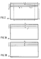
- Figures 3A-3F illustrate the method according to the invention for converting the high-definition television signal into two transmission signals.
- the high-definition television signal is subjected to a 2:1 vertical decimation separating alternate lines in the high-definition television signal and forming these lines as two separate signals.
- each line of Figure 3A is divided, over time, into three separate sections, for example, line A is divided into sections al, a and ar; line C is divided into sections cl, c and cr; etc.
- the line sections a, c, e, g, etc., in Figure 3C are separated and form the first transmission signal.
- lines X1, X2, X3, etc. are compressed in time and combined with the remaining line sections al/ar, cl/cr, el/er, gl/gr, etc, of Figure 3C, forming the second transmission signal.
- FIG. 4 shows, in block diagram form, an embodiment for an arrangement for converting a high-definition television signal into two transmission signals.
- a video source 10 provides a high-definition television signal having a luminance bandwidth in excess of 11.2 MHz., and forming, on display, sequentially scanned picture frames having 525 scanning lines and a frame rate of 60 Hz., which picture frames have an aspect ratio of 5-1/3:3.
- An output of the video source 10, carrying the separate color signals, red (R), green (G), and blue (B), is applied to a matrix circuit 12.
- the matrix circuit 12 generates a luminance signal Y and two chrominance signals R-Y, B-Y.
- the two chrominance signals are applied first to respective analog-to-digital converters 14 and 16 and then to a dual vertical low-pass filter 18 having a cut-off frequency of ⁇ /4, for application to a dual 2:1 vertical line decimator 20 which selects alternate lines from the input signals applied thereto.
- the dual vertical line decimator 20 is shown as controllable switches 21 having the switchable inputs thereof, switched at one-half the line frequency of the high-definition television signal, coupled to receive the two chrominance signals, and output terminals of the switches 21 being coupled to the outputs of the vertical line decimator 20.
- the outputs of the vertical line decimator 20 are applied to a 2-channel delay circuit 22 having a one line delay and then to first and second inputs of a 3-channel 1:2 time expansion circuit 24, which may be a buffer memory.
- the luminance signal from the matrix circuit 12 is applied, via an analog-to-digital converter 26, to a demultiplexer 28 which receives a clock signal of one-half the line frequency of the high-definition television signal.
- a first output of the demultiplexer 28 carrying, for example, the lines A, C, E, etc., is coupled to a delay circuit 30, having a one line delay, and then to a third input of the 3-channel 1:2 time expansion circuit 24.
- This 1:2 time expansion serves the dual purpose of expanding the duration of each line in the luminance and chrominance signals to occupy substantially the full line duration of a standard television line, and also of effectively halving the bandwidth of the respective signals.
- the expanded luminance and chrominance signals are then applied to a 3-channel demultiplexer 32 which separates the line segments a, c, e, g, etc., from the lines A, C, E, G, etc., as graphically shown in Figures 3C and 3E and applies these line segments to a first set of outputs 32.1.
- the outputs 32.1 are connected to a 3-channel 3:4 time expansion circuit 34, substantially similar to the time expansion circuit 24.
- the expanded output line segments a, c, e, g, etc. now substantially occupy the full duration of a line in a standard television signal and have a bandwidth equal to, or less than, 4.2 MHz., the bandwidth of a standard television signal.
- the chrominance signals therefor are then applied to a horizontal band-pass filter 36 and then to a modulator 38 for modulation onto standard chrominance subcarriers generated by oscillator 40.
- the modulated output signals of modulator 38, along with a pilot line, which may be a standard VIT signal, are then applied to an adder 42.
- the luminance signal for the line segments a, c, e, g, etc. is applied to a vertical comb pre-filter 44, the output therefrom being also applied to the adder 42.
- the output of the adder 42 is applied to a digital-to-analog converter 46 which forms the first transmission signal which is compatible with standard television receivers.
- the vertical comb pre-filter 44 is, in essence, a standard comb filter which, instead of having a composite video signal applied thereto for forming at the outputs thereof combed luminance and chrominance signals, has only the luminance signal applied.
- the output luminance signal therefrom is combed and contains spaces in the spectrum thereof into which the chrominance signals may be fitted.
- Two dimensional spectrum of the luminance signal, after filtering, is shown in Figure 5.
- a second output of the demultiplexer 28, carrying the lines B, D, F, H, etc., is applied to a delay circuit 48, having a one line delay, and then to a first (adding) input of a subtractor circuit 50.
- the first output of the demultiplexer 28 is further applied to a line delay circuit 52, the output therefrom and the input thereto being connected to the inputs of an adder circuit 54.
- the output of the adder circuit 54 is divided by two in a divider circuit 56 forming the average of every two lines of luminance in the signal at the first output of the demultiplexer 28. This average signal is then applied to a second (subtracting) input of the subtractor circuit 50.
- the output of the subtractor circuit 50 is then applied to a delay equalizing circuit 58 which has a fixed delay for compensating delays in other processing to be described, and then to a first input of a multiplexer 60.
- the 3-channel demultiplexer 32 has a second pair of outputs 32.2 which supply the luminance and chrominance signals, respectively, of the line segments al/ar, cl/cr, el/er, gl/gr, etc. These line signals are applied to a 3-channel 3:4 time expansion circuit 62 which is substantially identical to the 3-channel 3:4 time expansion circuit 34.
- the chrominance outputs of the 3-channel 3:4 time expansion circuit 62 are applied to a horizontal band-pass filter 64 and then to a modulator 66 for modulation onto standard chrominance subcarriers generated by oscillator 68. These modulated signals are then applied to an adder 70.
- the luminance output of the 3-channel 3:4 time expansion circuit 62 is applied to a vertical comb pre-filter 74, substantially similar to pre-filter 44, and then to adder 70.
- the output signal from the adder 70 is applied to a second input of the multiplexer 60.
- the output signal from the multiplexer 60 after being filtered in horizontal low-pass filter 74, is applied to a digital-to-analog cnnverter 76 which forms the second transmisson signal.
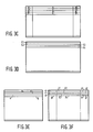
- the final transmission line formats for the first and second transmission signals are shown in Figure 6A and 6B, respectively.
- Figure 7 shows an embodiment for an arrangement for recombining the first and second transmission signals for use in a high-definition television receiver.
- the first and second transmission signals are applied to respective video clamp circuits 100 and 102 for application to a video timebase corrector circuit 104, after having first been digitized in analog-to-digital converters 106 and 108.
- the video timebase corrector circuit 104 compares the two transmission signals and synchronizes one with respect to the other by selectively delaying one or the other of the transmission signals.
- Respective outputs of the video timebase corrector circuit 104 are applied to respective set-up control circuits 110 and 112 which balance the brightness between the first and second transmission signals.
- the outputs of the video timebase corrector circuit 104 are also applied to a video pilot line comparator 114 which extracts and compares the pilot lines in the first and second transmission signals to a standard pilot line and generates control signals for the set-up control circuits 110 and 112.
- a video burst phase-locked loop 116 receives the video burst signal in the first transmission signal and applies a timing signal to the video pilot line comparator 114.
- the respective outputs of the set-up control circuits 110 and 112 are applied to respective gain control circuits 118 and 120, each of which having a control input connected to respective outputs of the video pilot line comparator 114.
- the output of the gain control circuit 118 is connected to a comb filter 122 which forms at its outputs the luminance and chrominance signals of the first transmission signal.
- the luminance signal is applied to a first input of a 3-channel 4:3 time compression circuit 124.
- the chrominance signals are first applied to a chroma phase correction circuit 126, having a control input connected to an output of the video pilot line comparator 114, and then to a chroma demodulator 128, having a timing signal input connected to an output of the video burst phase-locked loop 116.
- the outputs of the chroma demodulator 128, carrying the demodulated phase-corrected chrominance signals of the line segments a,c, e, etc., are connected to second and third inputs of the 3-channel 4:3 time compression circuit 124.
- the outputs of the 3-channel 4:3 time compression circuit 124 are applied to a first set of inputs of a 3-channel multiplexer 130.
- the output of the gain control circuit 120 is applied to a demultiplexer 132 which, at a first output, provides the digital audio signal, at a second output, a signal representing the lines X1, X2, X3, etc., and at a third output, a signal representing the line segments al/ar, cl/cr, el/er, etc.
- This third output of the demultiplexer 132 is applied to a comb filter 134.
- the luminance output of the comb filter 134 is connected to a first input of a 3-channel 4:3 time compression circuit 136, while the chrominance outputs of the comb filter 134 are applied to a chroma phase corrector 138, having a control input connected to an output of the video pilot line comparator 114.
- the outputs of the chroma phase corrector 138 are connected to a chroma demodulator 140, having a timing signal input connected to an output of the video burst phase-locked loop 116, and then to a second and a third input of the 3-channel 4:3 time compression circuit 136.
- the outputs of the 3-channel 4:3 time compression circuits 136 are applied to a second set of inputs of the 3-channel multiplexer 130.
- a first and second output of the 3-channel multiplexer 130, carrying the chrominance signals for the lines A, C, E, etc., are connected to a dual 2:1 time compression circuit 142, the outputs of which are connected to a dual 1:2 line interpolation circuit 144 which generates chrominance signals representing the lines A, B, C, D, etc.
- These chrominance signals are applied, via a dual digital-to-analog converter 146, to a first and second input of a matrix circuit 148.
- a third output of the 3-channel multiplexer 130, carrying the luminance signal for the lines A, C, E, etc., is connected to a 2:1 time compression circuit 150, the output of which is applied to a line delay circuit 152.
- An adder circuit 154 receives, at its inputs, the input and the output of the line delay circuit 152 and applies this sum signal to a divide-by-2 divider 156 forming an average of the luminance signals representing the lines A, C, E, etc., for example, (A+C)/2, (C+E)/2, etc., which is applied to an input of an adder circuit 158.
- the second output of the demultiplexer 132 is applied to a delay equalization circuit 160 for equalizing any difference in the delay in the signal applied thereto and that of the average signal at the output of the divider 156, the output of the delay equalization circuit 160 being applied to another input of the adder circuit 158.
- the output of the adder circuit 158 and the output of the 2:1 time compression circuit 150 are applied to respective inputs of a multiplexer 162 forming the luminance signal for the lines A, B, C, D, E, F, etc., which are applied first to an edge enhancement circuit 164 and then, via a digital-to-analog converter 166, to a third input of the matrix circuit 148.
- the matrix circuit 148 then forms the RGB signals for the high-definition television signal for application to a display having a 5-1/3:3 aspect ratio.
- Figure 8 shows an embodiment of the video timebase corrector 104.
- the outputs from the video clamp circuits 100 and 102 are applied to synchronizing signal separating circuits 170 and 172, respectively, which apply the respective line synchronizing signals to the reset inputs of counters 174 and 176 which receive clocking signals of, for example, 14.3 MHz.
- the outputs of the counters 174 and 176 are applied as addresses to a comparator 178.
- the output of the counter 174 is further applied to a second and a third input of a controllable switch 180 while the output of the counter 176 is connected to a first and a fourth input of the controllable switch 180.
- the controllable switch 180 includes switching contacts 180.1 and 180.2 which switch between the first and second inputs and the third and fourth inputs thereof, respectively, under control of the output signal from the comparator 178.
- the outputs of the video clamp circuits 100 and 102 are also applied to respective inputs of a controllable switch 182 and to a second and a third input, respectively, of a controllable switch 184.
- the switching contact 182.1 of switch 182, under control of the comparator 178 output, is connected to the data input of a memory 186, which receives write addresses from switching contact 180.1 and read addresses from switching contact 180.2.
- the output of the memory 186 is applied to a first and a fourth input of switch 184 which includes switching contacts 184.1 and 184.2 for switching, under control of the comparator 178 output, between the first and second inputs and the third and fourth inputs, respectively, of the switch 184. These switching contacts 184.1 and 184.2 are then connected to the inputs of the set-up control circuits 110 and 112, respectively.
- the video signal from video clamp circuit 102 is applied to the memory 186 and is delay for the duration of the difference in the addresses; conversely, if the address from counter 174 is greater than the address from counter 176, then the video signal from video clamp circuit 100 is delayed in memory 186.
- Figure 9 shows a block diagram of the pilot line comparator 114.
- the output signals from switching contacts 184.1 and 184.2 of the video timebase corrector 104 are applied to respective pilot line capture memories 190 and 192 which extract the respective pilot lines from the respective first and second transmission signals.
- the outputs from the memories 190 and 192 are applied to a microprocessor 194 which compares each of these pilot lines to a standard pilot line and generates respective control signals for adjusting the brightness in the set-up control circuits 110 and 112, the contrast in the gain control circuits 118 and 120, and the hue in the chroma phase correctors 126 and 138.
Landscapes
- Engineering & Computer Science (AREA)
- Multimedia (AREA)
- Signal Processing (AREA)
- Power Engineering (AREA)
- Television Systems (AREA)
- Color Television Systems (AREA)
Applications Claiming Priority (2)
| Application Number | Priority Date | Filing Date | Title |
|---|---|---|---|
| US856622 | 1986-04-25 | ||
| US06/856,622 US4694338A (en) | 1986-04-25 | 1986-04-25 | High-definition television transmission system |
Publications (2)
| Publication Number | Publication Date |
|---|---|
| EP0242922A2 true EP0242922A2 (de) | 1987-10-28 |
| EP0242922A3 EP0242922A3 (de) | 1988-07-06 |
Family
ID=25324100
Family Applications (1)
| Application Number | Title | Priority Date | Filing Date |
|---|---|---|---|
| EP87200722A Withdrawn EP0242922A3 (de) | 1986-04-25 | 1987-04-16 | Hochauflösendes Fernsehübertragungssystem |
Country Status (3)
| Country | Link |
|---|---|
| US (1) | US4694338A (de) |
| EP (1) | EP0242922A3 (de) |
| JP (1) | JPS62290283A (de) |
Cited By (3)
| Publication number | Priority date | Publication date | Assignee | Title |
|---|---|---|---|---|
| EP0361564A3 (de) * | 1988-08-31 | 1991-04-24 | Koninklijke Philips Electronics N.V. | Übertragung und Empfang von Fernsehsignalen von hoher Auflösung mit einer Zeit- und Frequenzmultiplexierung |
| EP0361563A3 (de) * | 1988-08-31 | 1991-05-08 | Koninklijke Philips Electronics N.V. | Fernsehkanal von hoher Auflösung mit einer Zeit- und Frequenzmultiplexierung |
| GB2260055A (en) * | 1991-09-28 | 1993-03-31 | Samsung Electronics Co Ltd | Colour television signal scanning format converting apparatus |
Families Citing this family (33)
| Publication number | Priority date | Publication date | Assignee | Title |
|---|---|---|---|---|
| US4947241A (en) * | 1986-04-25 | 1990-08-07 | North American Philips Corporation | Training signal for maintaining the correct phase and gain relationship between signals in a two-signal high definition television system |
| US4794447A (en) * | 1986-11-17 | 1988-12-27 | North American Philips Corporation | Method and apparatus for transmitting and receiving a high definition NTSC compatible television signal over a single DBS channel in time division multiplex form |
| US4945410A (en) * | 1987-02-09 | 1990-07-31 | Professional Satellite Imaging, Inc. | Satellite communications system for medical related images |
| US4802008A (en) * | 1987-02-09 | 1989-01-31 | Walling Paul J | Satellite communications system for medical related images |
| US5128761A (en) * | 1987-06-02 | 1992-07-07 | North American Philips Corporation | Method and apparatus from transmitting augmentation panel components on one channel of a two channel wide aspect ratio television signal transmission system |
| EP0370064A4 (en) * | 1987-07-27 | 1993-02-10 | David Geshwind | A method for transmitting high-definition television over low-bandwidth channels |
| US4965661A (en) * | 1988-08-04 | 1990-10-23 | Scientific-Atlanta, Inc. | Method and apparatus for increasing the definiton of an NTSC video signal using an augmentation channel |
| GB8721565D0 (en) * | 1987-09-14 | 1987-10-21 | Rca Corp | Video signal processing system |
| US4916532A (en) * | 1987-09-15 | 1990-04-10 | Jerry R. Iggulden | Television local wireless transmission and control |
| US4967272A (en) * | 1988-01-27 | 1990-10-30 | Communications Satellite Corporation | Bandwidth reduction and multiplexing of multiple component TV signals |
| GB8804720D0 (en) * | 1988-02-29 | 1988-03-30 | Rca Licensing Corp | Compatible widescreen tv |
| US4907069A (en) * | 1988-06-01 | 1990-03-06 | Zenith Electronics Corporation | Two-channel compatible HDTV system |
| US4879606A (en) * | 1988-06-06 | 1989-11-07 | General Electric Company | EDTV recording apparatus |
| US4866509A (en) * | 1988-08-30 | 1989-09-12 | General Electric Company | System for adaptively generating signal in alternate formats as for an EDTV system |
| US5214501A (en) * | 1988-10-03 | 1993-05-25 | North American Philips Corporation | Method and apparatus for the transmission and reception of a multicarrier high definition television signal |
| JPH02107085A (ja) * | 1988-10-17 | 1990-04-19 | Hitachi Ltd | テレビジヨン信号の撮像装置 |
| US4989091A (en) * | 1988-11-16 | 1991-01-29 | Scientific-Atlanta, Inc. | Scan converter for a high definition television system |
| JPH02156785A (ja) * | 1988-12-08 | 1990-06-15 | Sony Corp | 信号伝送装置 |
| US4905084A (en) * | 1989-01-30 | 1990-02-27 | Carole Broadcasting Technologies, Inc. | Compatible and spectrum efficient high definition television |
| US5067017A (en) * | 1989-01-30 | 1991-11-19 | Leo Zucker | Compatible and spectrum efficient high definition television |
| US5128758A (en) * | 1989-06-02 | 1992-07-07 | North American Philips Corporation | Method and apparatus for digitally processing a high definition television augmentation signal |
| US5179442A (en) * | 1989-06-02 | 1993-01-12 | North American Philips Corporation | Method and apparatus for digitally processing a high definition television augmentation signal |
| KR920009073B1 (ko) * | 1989-11-09 | 1992-10-13 | 삼성전자 주식회사 | Ntsc와 호환성을 갖는 고품위 tv시스템 |
| KR920010043B1 (ko) * | 1989-12-28 | 1992-11-13 | 삼성전자 주식회사 | 일반 텔리비젼과 고화질 텔리비젼의 화면신호 호환 장치 및 방법 |
| US5063444A (en) * | 1990-03-19 | 1991-11-05 | At&T Bell Laboratories | High definition television arrangement with signal selections adapted to the available transmission capacity |
| US5093725A (en) * | 1990-06-22 | 1992-03-03 | At&T Bell Laboratories | Dynamic signal modification for achieving interference reduction in concurrently transmitted signals |
| US5287180A (en) * | 1991-02-04 | 1994-02-15 | General Electric Company | Modulator/demodulater for compatible high definition television system |
| US5272525A (en) * | 1991-03-07 | 1993-12-21 | Recoton Corporation | System for local wireless transmission of signals at frequencies above 900 MHz |
| US5410735A (en) * | 1992-01-17 | 1995-04-25 | Borchardt; Robert L. | Wireless signal transmission systems, methods and apparatus |
| US5453796A (en) * | 1994-06-28 | 1995-09-26 | Thomson Consumer Electronics, Inc. | Signal swap apparatus for a television receiver having an HDTV main picture signal processor and an NTSC Pix-in-Pix signal processor |
| US5461427A (en) * | 1994-06-28 | 1995-10-24 | Thomson Consumer Electronics, Inc. | Television receiver having the capability to associate any HDTV and any NTSC channel |
| RU2214693C2 (ru) * | 2001-10-02 | 2003-10-20 | Волков Борис Иванович | Цифровая система телевидения высокой четкости |
| US7382937B2 (en) * | 2003-03-07 | 2008-06-03 | Hewlett-Packard Development Company, L.P. | Method and apparatus for re-constructing high-resolution images |
Family Cites Families (8)
| Publication number | Priority date | Publication date | Assignee | Title |
|---|---|---|---|---|
| NL8104476A (nl) * | 1981-10-01 | 1983-05-02 | Philips Nv | Televisiesysteem voor hoge-definitie televisie en er voor geschikte televisie zender en ontvanger. |
| GB2113941A (en) * | 1982-01-25 | 1983-08-10 | Philips Electronic Associated | Television transmission system |
| GB2122836A (en) * | 1982-06-11 | 1984-01-18 | Philips Electronic Associated | Television transmission system |
| GB2132443A (en) * | 1982-12-22 | 1984-07-04 | Philips Electronic Associated | Television transmission system |
| GB2132444A (en) * | 1982-12-22 | 1984-07-04 | Phillips Electronic And Associ | Television transmission system |
| GB2132846A (en) * | 1982-12-22 | 1984-07-11 | Philips Electronic Associated | Television transmission system |
| US4605950A (en) * | 1983-09-20 | 1986-08-12 | Cbs Inc. | Two channel compatible high definition television broadcast system |
| US4613903A (en) * | 1984-04-06 | 1986-09-23 | North American Philips Corporation | High-resolution television transmission system |
-
1986
- 1986-04-25 US US06/856,622 patent/US4694338A/en not_active Expired - Fee Related
-
1987
- 1987-04-16 EP EP87200722A patent/EP0242922A3/de not_active Withdrawn
- 1987-04-24 JP JP62100236A patent/JPS62290283A/ja active Pending
Cited By (4)
| Publication number | Priority date | Publication date | Assignee | Title |
|---|---|---|---|---|
| EP0361564A3 (de) * | 1988-08-31 | 1991-04-24 | Koninklijke Philips Electronics N.V. | Übertragung und Empfang von Fernsehsignalen von hoher Auflösung mit einer Zeit- und Frequenzmultiplexierung |
| EP0361563A3 (de) * | 1988-08-31 | 1991-05-08 | Koninklijke Philips Electronics N.V. | Fernsehkanal von hoher Auflösung mit einer Zeit- und Frequenzmultiplexierung |
| GB2260055A (en) * | 1991-09-28 | 1993-03-31 | Samsung Electronics Co Ltd | Colour television signal scanning format converting apparatus |
| GB2260055B (en) * | 1991-09-28 | 1995-06-07 | Samsung Electronics Co Ltd | Television signal converting apparatus |
Also Published As
| Publication number | Publication date |
|---|---|
| US4694338A (en) | 1987-09-15 |
| JPS62290283A (ja) | 1987-12-17 |
| EP0242922A3 (de) | 1988-07-06 |
Similar Documents
| Publication | Publication Date | Title |
|---|---|---|
| US4694338A (en) | High-definition television transmission system | |
| EP0589486B1 (de) | Kompatibilität von Fernsehübertragungen mit vergrössertem und normalem Bildformat | |
| US4605950A (en) | Two channel compatible high definition television broadcast system | |
| CA1231172A (en) | Decoder for extracting a 4:3 aspect ratio signal from a high definition television signal | |
| EP0113933B1 (de) | Fernseh-Übertragungssystem | |
| US4429327A (en) | Compatible television system with increased vertical resolution | |
| US4631574A (en) | Compatible high-definition television with extended aspect ratio | |
| US4574300A (en) | High-definition color television transmission system | |
| KR920004568B1 (ko) | 와이드스크린 텔레비젼 신호 엔코딩 시스템 및 엔코드된 텔레비젼 신호 수신 시스템 | |
| US4630099A (en) | Time multiplexing chrominance information for compatible high-definition television | |
| US4949166A (en) | Apparatus for combining and separating constituent components of a video signal | |
| US4794456A (en) | High-definition television transmission system | |
| US5001551A (en) | NISC compatible two-channel transmission apparatus for enhanced definition television | |
| US4651195A (en) | Monochrome-compatible color slow scan television system | |
| US4999701A (en) | High definition NTSC compatible television system with increased horizontal bandwidth and reduced color artifacts | |
| US4709256A (en) | Wide screen composite video signal encoder and standard aspect ratio decoder having barst and subcarrier components of different frequencies | |
| EP0317018A2 (de) | Hochauflösendes, NTSC-kompatibles Fernsehsystem mit erhöhter horizontaler Bandbreite und vermindertem Farbrauschen | |
| US5014122A (en) | Method and apparatus for encoding and transmission of video signals | |
| KR0186137B1 (ko) | 영상신호처리기의 휘도/색신호 분리회로 | |
| JPH0430789B2 (de) | ||
| JPS63133791A (ja) | 立体カラ−テレビジヨン信号生成回路 | |
| JPH04253489A (ja) | テレビジョン信号の送受信方式および送受信装置 | |
| JPS6036156B2 (ja) | 高品位テレビジヨン信号送受信方式 | |
| JPS61126885A (ja) | テレビジヨン信号発生方式 | |
| JPH04238482A (ja) | テレビジョン信号変換装置 |
Legal Events
| Date | Code | Title | Description |
|---|---|---|---|
| PUAI | Public reference made under article 153(3) epc to a published international application that has entered the european phase |
Free format text: ORIGINAL CODE: 0009012 |
|
| AK | Designated contracting states |
Kind code of ref document: A2 Designated state(s): DE ES FR GB IT |
|
| PUAL | Search report despatched |
Free format text: ORIGINAL CODE: 0009013 |
|
| AK | Designated contracting states |
Kind code of ref document: A3 Designated state(s): DE ES FR GB IT |
|
| 17P | Request for examination filed |
Effective date: 19881215 |
|
| 17Q | First examination report despatched |
Effective date: 19910129 |
|
| STAA | Information on the status of an ep patent application or granted ep patent |
Free format text: STATUS: THE APPLICATION IS DEEMED TO BE WITHDRAWN |
|
| 18D | Application deemed to be withdrawn |
Effective date: 19910809 |
|
| RIN1 | Information on inventor provided before grant (corrected) |
Inventor name: TSINBERG, MIKHAIL |