EP0242935B1 - Appareil détecteur de mouvement d'un signal vidéo - Google Patents
Appareil détecteur de mouvement d'un signal vidéo Download PDFInfo
- Publication number
- EP0242935B1 EP0242935B1 EP87300297A EP87300297A EP0242935B1 EP 0242935 B1 EP0242935 B1 EP 0242935B1 EP 87300297 A EP87300297 A EP 87300297A EP 87300297 A EP87300297 A EP 87300297A EP 0242935 B1 EP0242935 B1 EP 0242935B1
- Authority
- EP
- European Patent Office
- Prior art keywords
- coupled
- motion
- differences
- sums
- image
- Prior art date
- Legal status (The legal status is an assumption and is not a legal conclusion. Google has not performed a legal analysis and makes no representation as to the accuracy of the status listed.)
- Expired - Lifetime
Links
- 239000002131 composite material Substances 0.000 claims abstract description 48
- 238000001228 spectrum Methods 0.000 claims abstract description 12
- 230000003111 delayed effect Effects 0.000 claims description 15
- 230000001934 delay Effects 0.000 claims description 4
- 230000007717 exclusion Effects 0.000 claims 2
- 238000001514 detection method Methods 0.000 abstract description 15
- 230000007704 transition Effects 0.000 abstract description 10
- 238000004458 analytical method Methods 0.000 abstract 1
- 239000000523 sample Substances 0.000 description 82
- 239000011159 matrix material Substances 0.000 description 9
- 238000010586 diagram Methods 0.000 description 6
- 230000006870 function Effects 0.000 description 4
- 230000000694 effects Effects 0.000 description 3
- 241001290864 Schoenoplectus Species 0.000 description 2
- 230000003044 adaptive effect Effects 0.000 description 2
- 230000012447 hatching Effects 0.000 description 2
- 238000000034 method Methods 0.000 description 2
- 230000008569 process Effects 0.000 description 2
- 238000005070 sampling Methods 0.000 description 2
- 230000004075 alteration Effects 0.000 description 1
- 230000008901 benefit Effects 0.000 description 1
- 230000008859 change Effects 0.000 description 1
- 230000000295 complement effect Effects 0.000 description 1
- 230000001143 conditioned effect Effects 0.000 description 1
- 238000001914 filtration Methods 0.000 description 1
- 230000036039 immunity Effects 0.000 description 1
- 238000004091 panning Methods 0.000 description 1
- 230000000750 progressive effect Effects 0.000 description 1
- 238000013139 quantization Methods 0.000 description 1
- 230000009467 reduction Effects 0.000 description 1
- 230000004044 response Effects 0.000 description 1
Images

Classifications
-
- H—ELECTRICITY
- H04—ELECTRIC COMMUNICATION TECHNIQUE
- H04N—PICTORIAL COMMUNICATION, e.g. TELEVISION
- H04N9/00—Details of colour television systems
- H04N9/77—Circuits for processing the brightness signal and the chrominance signal relative to each other, e.g. adjusting the phase of the brightness signal relative to the colour signal, correcting differential gain or differential phase
- H04N9/78—Circuits for processing the brightness signal and the chrominance signal relative to each other, e.g. adjusting the phase of the brightness signal relative to the colour signal, correcting differential gain or differential phase for separating the brightness signal or the chrominance signal from the colour television signal, e.g. using comb filter
-
- H—ELECTRICITY
- H04—ELECTRIC COMMUNICATION TECHNIQUE
- H04N—PICTORIAL COMMUNICATION, e.g. TELEVISION
- H04N5/00—Details of television systems
- H04N5/14—Picture signal circuitry for video frequency region
- H04N5/144—Movement detection
Definitions
- This invention relates to apparatus for detecting time changes in images represented by video signals.
- Video signal processing circuitry such as field/frame comb filters, field/frame recursive filters or progressive scan generators for example, have been designed which significantly enhance the quality of images reproduced from video signals. These systems perform very well for images which contain no motion (either image object motion or camera panning). Conversely, when image motion does occur, such systems tend to introduce undesirable artifacts. Consequently, these memory based processing systems are designed to be motion adaptive, i.e. the systems are either altered or switched out of the signal processing path when image motion occurs.
- Typical motion detectors known in the art of video signal processing compare corresponding video signals from successive field or frame intervals. The assumption is made that if the interfield/frame video signals differ by more than a predetermined value motion has occurred.
- SNR's signal-to-noise ratios
- the signal differences that are averaged are selected to correspond to pixels that are symmetrically disposed horizontally, vertically or both about the pixel being examined. Some systems weight the signal differences being averaged so that the signal averages exhibit a low-pass response.
- Motion detectors which examine field/frame differences to determine the occurrence of motion are designed to operate on component rather than composite video signals. The reason for this is that chrominance components of composite video signals do not have similar phase relationships from frame-to-frame. Inherent frame-to-frame chrominance differences will produce motion signals even for still images. In order to preclude false motion detection when successive frames of composite video signal are compared, the composite video signal is typically limited to the low frequency luminance spectrum before comparison.
- Motion detectors which do operate on composite video and a) separate the luminance and chrominance components, b) align the phase of the corresponding frame-to-frame chrominance components, c) recombine the phase altered chrominance component with the luminance component and d) take the interframe difference of the composite and chrominance phase altered composite video signals.
- This approach to detecting motion in composite video signals is not satisfactory because luminance and chrominance components cannot be completely separated in the chrominance spectrum of the composite video signal.
- the unseparated or residual luminance component in the separated chrominance signal undergoes an alteration during the chrominance phase alignment process. When this altered high frequency luminance is recombined and the interframe signal differences are taken, signal differences may occur in the absence of motion resulting in false motion detection.
- GB-A-2O45 574 discloses a video movement detection apparatus suitable for detecting picture movement and/or noise on a video signal.
- the apparatus comprises a first detector for detecting differences frame by frame on a portion of picture having a plurality of picture points from more than one line, a second detector for detecting differences frame by frame from a portion of picture having a plurality of picture points from the same line, and a third detector for detecting differences frame by frame from a portion of a picture comprising a single picture point. Movement is determined to have taken place when the differences measured by the respective detectors exceed predetermined thresholds.
- the selected thresholds are typically of different values to provide the capability of distinguishing between noise and movement in varying conditions.
- the present invention seeks to provide detection of motion in a video signal with a minimum of false detection signals due to noise and cross components.
- a signal interimage motion detector comprising: a signal interimage motion detector comprising an input terminal (CV) for receiving a video signal; and means coupled to said input terminal for providing differences between video signals from successive image periods; characterized by first means, coupled to said means for providing differences, for summing a plurality of said differences, said plurality of differences including a difference corresponding to an image point currently under examination for interimage motion, and differences corresponding to image points proximate said image point under examination occurring in a horizontal image line containing said image point under examination and in a preceding horizontal image line to produce first summed differences; second means, coupled to said means for providing differences, for summing a plurality of said differences, said plurality of differences including a difference corresponding to said image point under examination, and differences corresponding to image points proximate said image point under examination occurring in said horizontal image line containing said image point under examination and in a succeeding horizontal image line to produce second summed differences; and means coupled to said first and second summing means, for
- the sample rate is selected to be four times the color subcarrier rate and phase locked to color burst, though other sample rates may be selected.
- the elements are illustrated in functional terms which are applicable to both analog and digital signal processing environments since the invention may be practiced with either analog or digital circuits. All of the individual circuit elements, both digital and analog, are well known in the art of video signal processing, and, thus, will not be described in detail. Depending on the choice of processing circuitry it may be necessary to include compensating signal delay elements to align in time signals in the different circuit paths, but one skilled in the art of circuit design will readily comprehend and include such delays.
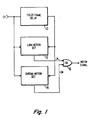
- composite video (CV) signal which may be supplied from a television tuner in a TV receiver environment, from a color camera, or from the signal pickup circuitry in a VCR environment etc. is applied to delay element 10, a luminance motion detector 12 and a chrominance motion detector 14. Delayed signal from delay element 10 is coupled to respective second input connections of detectors 12 and 14.
- delay element 10 will typically delay the applied signal CV by precisely one frame interval.
- delay element 10 may delay the signal CV by two frame intervals.
- Luminance motion detector 12 compares the current and delayed video luminance component of the composite video signals and generates a motion signal (LM) if a predetermined difference exits between the two luminance signals.
- Chrominance motion detector 14 compares the current and delayed chrominance components of the composite video signals and generates a motion signal (CM) if a predetermined difference exists between the two chrominance signals.
- the motion signals LM and CM from detectors 12 and 14 are coupled to respective inputs of an OR gate 16 which develops a motion signal when either the luminance or chrominance motion detectors generate a motion signal.
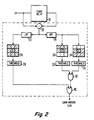
- FIGURE 2 illustrates one embodiment of a luminance signal motion detector which may be implemented as motion detector 12 in FIGURE 1.
- the current and delayed composite video signals are coupled to respective input terminals of the subtracter 20.
- Subtracter 20 develops frame difference samples which are coupled to the input terminals of a low-pass filter 22 and a high-pass filter 24.
- Low-pass filter 22 passes that portion of the composite video signal frequency spectrum not normally occupied by the chrominance component.
- high-pass filter 24 (which may be a bandpass filter) passes that portion of the composite video signal spectrum which is normally occupied by the chrominance component.
- the signal differences provided by low-pass filter 22 are coupled to a signal combining element 26.
- Combining element 26 sums a number of the frame difference samples.
- Element 26 is drawn as a matrix of three rows with three squares in each row. Each of the squares represents a signal difference sample.
- the central square corresponds to the image point or sample under examination for image motion.
- the square to the left and right of the central box correspond to sample differences occurring on the same horizontal image line. However, it is to be understood that these two sample differences need not correspond to the immediately preceding and succeeding sample differences in the stream of sample differences occurring at the four-times color subcarrier rate.
- the squares in the rows above and below the middle row correspond to sample differences from horizontal image lines occurring before and after the image line containing the pixel under examination.
- the cross hatching is intended to illustrate that each of the sample differences represented by the squares in the illustrative 3x3 matrix contribute to the sum generated by combining element 26.
- Threshold detector 28 provides a logic one output signal for the condition that the sum exceeds a predetermined magnitude and a logic zero otherwise.
- a digital embodiment of the threshold detector 28 may comprise the cascade connection of an absolute value circuit and an N-input OR gate.
- the absolute value circuit is configured to convert all sums to a single polarity signal. If the output signal of the absolute value circuit is a parallel N-bit signal, the M more significant bits are coupled to the M more significant input connection of the N-input OR gate.
- the N-M lesser significant bit connections of the OR gate are coupled to a logic zero signal. In such a configuration the OR gate will develop a logic one output signal for sums having magnitudes exceeding the values (2 N-M -1).
- the output signal of the threshold detector 28 is coupled to one input connection of the two-input OR gate 40.
- the output signal from the high-pass filter 24 is coupled to two signal combining circuits 30 and 34.
- Combining circuit 30 combines sample differences from the horizontal image line containing the pixel under examination and a horizontal image line preceding the image line containing the pixel under examination.
- the central square in the illustrative matrix corresponds to the pixel under examination.
- the cross hatching indicates the samples that are combined by element 30.
- the samples that are combined from the two lines are vertically aligned relative to the displayed image.
- the preceding line is selected such that the vertically aligned samples have an antiphase color subcarrier relationship. For example, if the composite video signal is an NTSC signal the preceding line is the immediately preceding image line, or the third, fifth, etc. most immediate preceding line.
- the difference samples to the right and left of the difference sample corresponding to the pixel under examination need not be the difference samples immediately preceding and following the control difference sample.
- the output of the combining element 30 is coupled to a threshold detector 32 which develops a logic one output signal for the condition that the combined difference samples exceed a predetermined magnitude and a logic zero otherwise.
- the output signal from threshold detector 32 is coupled to one input connection of a two input AND gate 38.
- Combining element 34 is similar to combining element 30 except that it combines sample differences from the horizontal image line containing the difference sample corresponding to the pixel under examination with difference samples from a horizontal image line occurring later in time.
- the combined difference samples from combining element 34 are coupled to a threshold detector 36 which functions similarly to threshold detector 32.
- the output signal from threshold detector 36 is coupled to a second input connection of the AND gate 38.
- AND gate 38 produces a logic one output signal only when both threshold detectors 32 and 36 concurrently produce logic one output signals.
- the output signal from AND gate 38 is coupled to a second input connection of OR gate 40.
- OR gate 40 produces a logic one output signal, indicating image motion, whenever threshold detector 28 or AND gate 38 output logic one signals.
- elements 22, 26 and 28 detect image motion represented by luminance signal defining coarse image object detail.
- Elements 24, 30-38 detect image motion represented by luminance signal defining fine image object detail.
- parallel combining-circuit-threshold-detection circuits are incorporated to preclude false motion detection resulting from particular image chrominance transitions as will be explained with reference to FIGURE 3.
- threshold values selected for threshold detectors 28, 32 and 36 may be fixed constants or made variable as a function of signal-to-noise ratio (SNR) as is known in the art of e.g. video signal recursive filters.
- SNR signal-to-noise ratio
- threshold detectors 32 and 36 will be designed to respond to like threshold values.
- Threshold detector 28 in general will require a dissimilar threshold value because a) combining element 26 combines a larger number of difference samples than elements 30 and 34, and b) the difference samples combined by element 26 contains less cross components than the difference samples combined by elements 30 and 34.
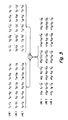
- Shown in FIGURE 3 are corresponding samples from portions of three successive horizontal image lines of two successive frames of NTSC composite video.
- the samples occur in conformance to a four times subcarrier sampling rate phase locked to the subcarrier.
- Y ij values correspond to the luminance component.
- the ⁇ I ij and ⁇ Q ij values correspond to quadrature related chrominance components wherein the ⁇ signs designate sampling phase and not necessarily sample polarity.
- successive I values along a horizontal line have substantially equal magnitude and are of opposite polarity.
- successive Q values have substantially equal magnitudes and are of opposite polarity. Due to the relatively high redundancy of video signal information vertically aligned samples from line-to-line represent like picture information.
- the frame-to-frame sample differences as developed by e.g. subtracter 20 in FIGURE 2 are also illustrated.
- the ⁇ Y ij terms represent the luminance differences and the ⁇ (I ij +I′ ij ) and ⁇ (Q ij +Q′ ij ) terms represent chrominance sample differences.
- the low-pass filter 22 attenuates the ⁇ (I ij +I′ ij ) and ⁇ (Q ij +Q′ ij ) terms so that combining circuit only operates on lower frequency ⁇ Y ij luminance differences. If no image changes occur between frames, the values ⁇ Y ij will be zero except for noise contributions, i.e. electrical noise or quantization noise.
- summing a number of the ⁇ Y ij terms as in combining element 26 will tend to average the noise contribution to zero. Thresholding the sums in detector 28 is performed to add a further degree of noise immunity. Disregarding noise, if interframe image changes occur, a number of the ⁇ Y ij samples will be non zero. This is so even for slight image changes because the signal is over sampled. Thus, summing a number of ⁇ Y ij values in the vicinity of the pixel under examination will produce a larger motion signal than examining a single pixel difference sample. The SNR of the motion signal is therefore significantly enhanced.
- the sample differences applied to combining elements 30 and 34 contain both high frequency luminance differences and chrominance information. Note that for NTSC signals, frame-to-frame chrominance components are antiphasal. Subtracting the interframe chrominance components has the effect of summing them as indicated in the matrix of difference sample values.
- Combining element 30 sums the difference samples from e.g. lines l and 2 shown in FIGURE 3, and combining element 34 sums the difference samples from e.g. lines 2 and 3 shown in FIGURE 3.
- the pixel under examination corresponds to a difference sample in line 2 either the sum from combining element 30 or 34 may indicate high frequency luminance motion.
- the parallel detectors (30-32) and (34-36) are incorporated to preclude false motion detection. Images occur wherein from line-to-line there may be a chrominance transition from one color to a different color or a transition from a colored image to a black and white image. For either of these conditions summing the line-to-line difference samples will not cancel the chrominance component resulting in a false detection. However, it is extremely unlikely that such a condition will concurrently occur between both the pair of lines 1 and 2 and the pair of lines 2 and 3.
- detectors (30-32) and (34-36) generate a motion signal, one of these special image conditions, and not motion, is the cause. To preclude false detection, the two detectors are ANDED together. In effect detector (30-32) in conjunction with the AND gate 38 monitors detector (34-36) for such false motion detection and vice versa.
- the effect of chrominance transitions causing false detection may be reduced further by judicious selection and weighting of the difference samples combined in elements 30 and 34.
- the difference samples be designated S ij where the indices correspond to the indices of the ⁇ Y ij components in FIGURE 3.
- the difference sample S23 correspond to the pixel under examination.
- a combining element 30 which combines samples S11, S21, S15, S25 in a ratio of 1:2 with samples S13 and S23 will be significantly less sensitive to vertical chrominance transitions because the weighting tends to structure the combining circuitry to perform notch filtering at the chrominance subcarrier frequency.
- Combining element 34 will be similarly designed to sum the difference samples S21, S31, S25, S35 in the ratio of 1:2 with the difference samples S23 and S33.
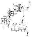
- FIGURE 4 shows circuitry for realizing this latter embodiment.
- the low-pass filtered difference samples from filter 22 are coupled to two cascade connected delay elements 52 and 54 and to one input connection of a sample summing circuit 56.
- Delay elements 52 and 54 each provide a like delay interval of an integral number of sample periods e.g. one, two or three sample periods. Delayed difference samples from delay elements 52 and 54 are coupled to respective second and third input connections of summing circuit 56.
- the difference sample sums from summing circuit 56 are coupled to the cascade connection of two one-horizontal-line delay elements 58 and 60.
- the output signals from summing circuit 56, delay element 58 and delay element 60 are coupled to respective input connections of summing circuit 62 and represent sample sums from three horizontal image lines.
- Summing circuit 62 produces a difference sample sum of three difference samples from each of three successive lines. This sample sum is coupled to the threshold detector 64 which corresponds to the threshold detector 28 in FIGURE 2.
- the output signal from threshold detector 64 corresponds to a low frequency luminance motion signal and is coupled to an input connection of OR gate 86.
- the difference samples from the subtracter 20 are coupled to the minuend input connection of subtracter 50 and the low-pass filtered difference samples from filter 22 are coupled to the subtrahend input connection of subtracter 50.
- the frequency spectrum exhibited by the signal output from subtracter 50 is complementary to the signal spectrum of the signal output from the low-pass filter 22. In other words the combination of subtracter 50 and low-pass filter 22 forms a high-pass filter with respect to the composite video signal spectrum.
- High-pass filtered difference samples from subtracter 50 are coupled to the cascade connection of the two delay elements 66 and 68.
- delay elements 66 and 68 each provide signal delays of two sample periods.
- delay elements 68 and 66 and the input of delay element 66 provide every second sample difference i.e. S i1 , S i3 and S i5 .
- the output connection of subtracter 50, delay element 66 and delay element 68 are coupled to respective input connections of weighting and combining circuit 70.
- the outer difference samples S i1 and S i5 are weighted by one-half and summed with the difference sample S i3 , to form the weighted sum of three sample differences from one horizontal image line.
- the weighted sums from weighting and combining circuit 70 are coupled to the cascade connection of the two one-horizontal-line delay elements 72 and 74.
- the input and output connections of delay element 72 are coupled to respective input connections of adder 76.
- Adder 76 produces difference sample sums which correspond to the sums produced by combining element 30 in FIGURE 2.
- the input and output connections of delay element 74 are coupled to respective input connections of a further adder 78.
- Adder 78 produces difference sample sums corresponding to the output sums provided by combining element 34 of FIGURE 2.
- the output sums provided by adders 76 and 78 are coupled to threshold detectors 80 and 82 respectively.
- the output connections of threshold detectors 80 and 82 are coupled to respective input connections of the two-input AND gate 84, the output of which is coupled to the second input connection of OR gate 86.
- the full band signal differences may be applied directly to the high frequency detectors, i.e. (30-32) and (34-36), and the low frequency detector (26-28) omitted.
- the advantage of this arrangement is a reduction in hardware.
- the disadvantage is a small penalty in terms of motion/noise discrimination because the low frequency detector (26-28) exhibits a better motion/noise ratio due to the symmetry of differences selected.
- FIGURE 5 illustrates a detector for detecting inter-image motion represented by the chrominance component of composite video signal and which may be used for the motion detector 14 in FIGURE 1.
- current composite video signal samples and corresponding frame delayed composite video samples are coupled to respective input connections of an adder 90. If there are no inter-image changes, adder 90 will produce sample sums corresponding to 2Y ij .
- the chrominance components being antiphase from frame-to-frame cancel in the summing process.
- the sums output by adder 90 will correspond to 2Y ij + ⁇ Y ij ⁇ I ij or to 2Y ij + ⁇ Y ij ⁇ Q ij , where ⁇ Y ij is the image change represented by the luminance component and ⁇ I ij and ⁇ Q ij are image changes represented by the quadrature related chrominance components.
- the chrominance changes ⁇ I ij and ⁇ Q ij alternate in polarity at the subcarrier rate and thus are designated ⁇ I and ⁇ Q.
- the changes ⁇ I ij and ⁇ Q ij will tend substantially to be antiphasal from line-to-line (NTSC) and antiphasal every two lines for PAL signals.
- the sample sums produced by adder 90 are applied to a filter 92 which attenuates samples having frequencies outside the band of frequencies normally occupied by the chrominance component of composite video signal.
- the filtered sample sums are coupled to sample combining circuits 94 and 96.
- Combining element 94 combines sample sums from the horizontal image line containing the sample sum representing the current pixel under examination and sample sums from a previously occurring horizontal image line.
- Combining element 96 combines sample sums from the horizontal image line containing the sample sum, representing the pixel under examination and sample sums from a succeeding horizontal image line. All of the sample sums combined by either element 94 or 96 are in relatively close proximity to the sample sum representing the pixel under examination though not necessarily immediately adjacent.
- Combining elements 94 and 96 are represented by like matrixes of three rows of three squares per row.
- Each row represents a portion of sample sums from one image line.
- Each square represents a sample sum. However, only the sample sums represented by a square containing a plus or a minus sign are included in combined samples produced by combining elements 94 and 96.
- the plus and minus signs designate the polarity with which each of the sample sums are combined.
- the sample sums of each vertically aligned pair of sums are combined with opposite polarity. Because of the high line-to-line redundancy of most images the luminance components in the vertically aligned sample sums will cancel.
- the polarity selection by which the sample sums are combined also tend to render the chrominance component differences to a single like polarity so that all non zero chrominance differences sum constructively to produce a motion signal with enhanced SNR.
- Threshold circuits 98 and 100 develop logic one output signals if the signal applied to its respective input connection exceeds a predetermined value and develop logic zeroes otherwise.
- the output connection of threshold circuits 98 and 100 are coupled to respective input connections of the two-input AND gate 102.
- AND gate 102 produces a logic one output signal, indicating image motion, only when both of the threshold circuits 98 and 100 concurrently produce logic one output signals.
- the chrominance motion detector utilizes parallel detectors (94,98) and (96,100) to preclude false motion detection resulting from line-to-line or vertical luminance transitions which would defeat luminance cancellation in either one or the other of the combining circuits. It is very unlikely that such a luminance transition will occur between the two lines from which samples are combined by circuit 94 and concurrently between the two lines from which samples are combined by circuit 96. Thus, for line-to-line luminance transitions not due to image motion, only one of the detectors (94,98) or (96,100) will develop a motion signal, which is insufficient to condition AND gate 102 to produce a chrominance motion signal.
- FIGURE 6 shows one embodiment of the FIGURE 5 motion detector in greater detail.
- elements designated with like numerals to those in FIGURE 5 perform like functions.
- the high-pass filtered sample sums from filter 92 are coupled to the cascade connection of two similar delay elements 110 and 112.
- Delay elements 110 and 112 each delay the sample sums by a small number of sample periods. It is advantageous that delay elements 110 and 112 be designed to delay samples by two sample periods to ensure more complete luminance cancellation. This result arises by virtue of including only one of the quadrature chrominance components (e.g. the ⁇ I ij component) in the combined sample sums.
- the sample sums from the filter 92 and the twice delayed sample sums from delay element 112 are coupled to non-inverting input connections of the summing circuit 114.
- the delayed sample sums from delay element 110 are coupled to an inverting input connection of summing circuit 114.
- Circuit 114 develops the sum of the sample sums applied to its non-inverting input connections and the negative of the sample sums applied to its inverting input connection, which sums correspond to the sums of sample sums along one horizontal image line. Note that the inverting and non-inverting inputs may be interchanged without altering the system function. In addition, more than three sample sums per horizontal line may be combined. Finally, the sample sums may be weighted as in the FIGURE 4 circuitry.
- the combined sums from the summing circuit 114 are coupled to the cascade connection of two one-horizontal-line delay elements 116 and 118. Delayed combined sums occurring at the output connections of delay element 118 correspond to the combination of sample sums from the top row of squares in the matrix of elements 94 and 96 in FIGURE 5.
- the output connections of delay element 116 provides combined sums corresponding to the combination of sample sums represented by the middle row of squares in the matrix of elements 94 and 96 in FIGURE 5, and the output connection of combining element 114 provides combined sums corresponding to the combination of sample sums represented by the bottom row of squares in the matrix elements 94 and 96.
- the combined sums from the output connections of delay elements 116 and 118 are applied to the subtrahend and minuend input connections of subtracter 122 respectively.
- Substracter 122 combines the combined sums in accordance with the respective sample sum polarities indicated in the matrix of element 94.
- the output of subtracter 122 is threshold detected in threshold circuit 98, the output of which in coupled to one input connection of AND gate 102.
- the combined sum from the output connections of combining element 114 and delay element 116 are coupled to the minuend and subtrahend input connections respectively of subtracter 120.
- Subtracter 120 combines the combined sums in accordance with the respective sample sum polarities indicated in the matrix of element 96 of FIGURE 5.
- the combined sums produced by subtracter 120 are threshold detected in threshold circuit 100, the output of which is coupled to a second input connection of AND gate 102.
- AND gate 102 develops a chrominance motion, signal on the condition that the combined sums from subtracters 120 and 122 concurrently exceed a predetermined threshold value.
- the circuitry initially combines sample sums occurring in respective horizontal lines and then combines the combined samples from the respective horizontal lines. It will be appreciated by those skilled in the art of signal processing that sample sums from the different horizontal lines may be combined first, and then these combined sums combined horizontally.
- a further alternative embodiment may provide all of the sample sums and/or difference signals of the respective matrices simultaneously, which samples may then be combined in a tree arrangement of adders/subtractors.
- the motion indicating output signals are single bit bilevel signals. It will be appreciated by those skilled in the art that the motion indicating signals may be multi-bit signals which may correspond, for example, to the average of the combined samples produced by the respective combining means, or the differences between the combined samples and the appropriate threshold values etc.
Landscapes
- Engineering & Computer Science (AREA)
- Multimedia (AREA)
- Signal Processing (AREA)
- Processing Of Color Television Signals (AREA)
- Color Television Systems (AREA)
- Details Of Television Scanning (AREA)
- Vehicle Body Suspensions (AREA)
- Ultra Sonic Daignosis Equipment (AREA)
- External Artificial Organs (AREA)
- Enzymes And Modification Thereof (AREA)
- Testing, Inspecting, Measuring Of Stereoscopic Televisions And Televisions (AREA)
- Closed-Circuit Television Systems (AREA)
Claims (14)
- Un détecteur de mouvement interimages d'un signal comprenant :
une borne d'entrée (CV) pour recevoir un signal vidéo ; et
un moyen (10, 20) couplé à la borne d'entrée pour produire des différences entre les signaux vidéo de périodes d'images successives;
caractérisé par une premier moyen (30), couplé audit moyen produisant des différences, pour additionner un certain nombre desdites différences, ce certain nombre de différences comprenant une différence correspondant à un point d'image actuellement sous examen pour mouvement interimages et des différences correspondant à des points d'image à proximité du point d'image sous examen se produisant dans une ligne d'image horizontale contenant ledit point d'image sous examen et dans une ligne d'image horizontale précédente pour produire des premières différences additionnées ;
un second moyen (34), couplé audit moyen pour produire des différences, pour additionner un certain nombre desdites différences, ledit certain nombre de différences comprenant une différence correspondant à un point d'image sous examen, et des différences correspondant à des points d'image à proximité du point d'image sous examen se produisant dans la ligne d'image horizontale contenant ledit point d'image sous examen et dans une ligne d'image horizontale successive pour produire des secondes différences additionnées ; et
un moyen (32, 36, 38), couplé aux premier et second moyens d'addition, pour produire un signal de mouvement chaque fois que des premières différences additionnées excèdent concurremment une valeur de grandeur prédéterminée. - Un détecteur selon la revendication 1 pour détecter un mouvement interimages dans des images représentées par un signal vidéo composé où :
la borne d'entrée (CV) est destinée à recevoir le signal vidéo composé (CV) ;
le moyen de production (10, 20) comprend un moyen à retard (10), couplé à la borne d'entrée, pour produire des reproductions du signal vidéo composé retardé par un nombre entier, comprenant un, de périodes d'image et un moyen (20) couplé à la borne d'entrée et au moyen à retard pour produire des différences du signal vidéo composé et du signal vidéo composé retardé ;
et comprenant de plus un moyen (24), comprenant un moyen couplé au moyen de production (20) , pour laisser passer à une première borne de sortie des différences ayant des composantes de fréquence normalement occupées par des composantes de chrominance du signal vidéo composé à l'exclusion relative d'autres composantes de fréquence du signal vidéo composé ;
et où des premier et second moyens (30, 34) sont couplés à la première borne de sortie ;
et le moyen de production de signal de mouvement comprend un premier détecteur de seuil (32), couplé au premier moyen, pour produire un signal d'indication de mouvement lorsque des différences additionnées appliquées à celui-ci excèdent une grandeur prédéterminée,
un second détecteur de seuil (36), couplé au second moyen pour produire un signal d'indication de mouvement lorsque des différences additionnées appliquées à celui-ci excèdent une grandeur prédéterminée, et
un moyen (38, 84), couplé aux premier et second détecteurs de seuil pour produire à une seconde borne de sortie, un signal d'indication de mouvement chaque fois que les premier et second détecteurs de seuil produisent concurremment des signaux d'indication de mouvement. - Un détecteur selon la revendication 2 qui comprend de plus :
un moyen (22) , couplé au moyen précité (20) pour produire des différences, pour laisser passer à une troisième borne de sortie des différences ayant des composantes de fréquence du signal vidéo composé ne se produisant pas normalement dans le spectre de fréquences occupé par la composante de chrominance précitée ;
un troisième moyen (26, 56 62), couplé à la troisième borne de sortie, pour additionner un certain nombre desdites différences, le certain nombre des différences correspondant à des points d'image disposés symétriquement au point d'image précité sous examen ;
un troisième détecteur de seuil (28, 64), couplé au troisième moyen pour produire un signal d'indication de mouvement lorsque des différences additionnées appliquées à celui-ci excèdent une grandeur prédéterminée ; et
un moyen (40, 86) couplé au troisième détecteur de seuil et à la seconde borne de sortie pour produire à une quatrième borne de sortie un signal d'indication de mouvement chaque fois que le troisième détecteur de seuil ou la seconde borne de sortie produit un signal d'indication de mouvement.
- Un détecteur selon la revendication 3 où les différences précitées se produisent comme différences de données échantillonnées et le troisième moyen précité (26) comprend :
une connexion en cascade
d'un moyen (56) pour additonner un certain nombre de différences d'échantillons correspondant aux points d'image se produisant dans une ligne d'image horizontale et
d'un moyen (62) pour additionner les différences d'échantillons additionnées correspondant aux points d'image se produisent dans des lignes d'images horizontales successives. - Un détecteur selon l'une des revendications 2 à 4 où les différences précitées se produisent comme différences de données échantillonnées et le premier moyen précité (30) comprend :
un premier moyen d'addition (70) couplé à la première borne de sortie précitée pour additionner des échantillons de différence correspondant à des points d'image se produisant dans la même ligne d'images horizontale ; et
un second moyen d'addition (78) couplé au premier d'addition, pour additionner des échantillons de différences additionnées produites par le premier moyen d'addition à partir de deux lignes d'images horizontales différentes ; et
où le second moyen précité (34) comprend un moyen (76) couplé au premier moyen d'addition (70) pour additionner des échantillons de différences additionnées produits par le premier moyen d'addition à partir de deux lignes d'images horizontales dont l'une est différente des lignes d'images horizontales additionnées par le second moyen d'addition. - Un détecteur selon l'une des revendications 2 à 5 comprenant de plus :
un moyen (90) couplé à la première borne d'entrée précitée et au moyen à retard précité (10) pour produire des sommes du signal vidéo composé et du signal vidéo composé retardé précités ;
un moyen de filtrage (92), couplé au moyen (90) pour produire des sommes pour laisser passer les composantes de fréquence desdites sommes se produisant normalement dans la bande de fréquences du signal vidéo composé occupée par les composantes de chrominance ;
un premier moyen additionnel (94, 114, 122), couplé au moyen de filtrage (92) pour additionner un certain nombre, pair en nombre desdites sommes, le certain nombre de sommes correspondant aux points d'image se produisant dans une ligne horizontale contenant le point d'image sous examen et des points d'image se produisant dans une ligne d'image horizontale précédant la ligne d'image horizontale contenant le point d'image sous examen, le premier moyen additionnel (94, 114, 122) additionnant des sommes alternées le long d'une ligne d'image horizontale de polarité opposée et où une moitié dudit certain nombre de sommes a un sens de polarité positif et une moitié dudit certain nombre de sommes a un sens de polarité négative ;
un premier détecteur de seuil additionnel (98), couplé au premier moyen additionnel (94, 114, 122) pour produire un signal d'indication de mouvement chaque fois que des signaux additionnés produits par le premier moyen de combinaison excèdent une grandeur prédéterminée;
un second moyen additionnel (96, 114, 120), couplé au moyen de filtrage (92), pour additionner un certain nombre pair en nombre, desdites sommes, ledit certain nombre de sommes correspondant à des points d'image se produisant dans une ligne horizontale contenant le point d'image sous examen et des points d'image se produisant dans une ligne d'image horizontale suivant la ligne d'image horizontale contenant le point d'image sous examen, le second moyen additionnel (96, 114, 120) additionnant des sommes alternées le long d'une ligne d'image horizontale de polarité opposée et où une moitié dudit certain nombre de sommes est additionnée dans un sens de polarité positive et une moitié de la somme des polarités est additionnée dans un sens de polarité négative ;
un second détecteur de seuil additionnel (100), couplé au second moyen additionnel (96, 114, 120) pour produire un signal d'indication de mouvement chaque fois que des signaux additionnés produits par le second moyen additionnel excèdent une grandeur prédéterminée ;
un moyen (102) couplé aux premier et second détecteurs de seuil additionnels pour produire un signal d'indication de mouvement de chrominance lorsque les premier et second détecteurs de seuil additionnels produisent concurremment des signaux d'indication de mouvement. - Un détecteur selon la revendication 6 qui comprend de plus un moyen (16) répondant au signal d'indication de mouvement de chrominance précité et au signal d'indication de mouvement précité produits par la seconde borne de sortie précitée pour produire un signal d'indication de mouvement à l'apparition du signal d'indication de mouvement de chrominance ou du signal d'indication de mouvement produit à la seconde borne de sortie.
- Un détecteur selon la revendication 6 ou la revendication 7 où les sommes précitées se produisent comme sommes de données échantillonnées et le premier moyen additionnel (94) précité comprend :
une connexion en cascade de premier et second éléments à retard (110, 112) couplée au filtre précité (92) pour produire des reproductions retardées desdites sommes les premier et second éléments à retard produisant chacun des retards identiques d'un nombre entier de périodes d'échantillon ;
un moyen (114) couplé au filtre (92) et au second élément à retard (112) pour additionner des échantillons de somme dudit filtre et retarder de deux fois des échantillons de somme du second élément à retard de sens de polarité opposé avec des échantillons de somme retardés une fois du premier élément à retard (110) pour produire des échantillons de somme additionnés horizontalement ;
un autre moyen à retard (118) couplé au moyen (114) pour produire des échantillons de somme additionnés horizontalement, ledit autre moyen à retard (118) produisant des retards d'échantillon d'une période de ligne d'image horizontale ; et
un autre moyen (122) couplé à une entrée et une sortie de l'autre moyen à retard (118) pour additionner lesdits échantillons de somme additionnés horizontalement de polarité opposée. - Un détecteur selon l'une des revendications 6 à 8 dans lequel la ligne d'image horizontale précédente précitée est choisie de telle sorte que les composantes de chrominance dans celle-ci ont une relation en opposition de phase avec les composantes de chrominance correspondant à la ligne d'image horizontale précitée contenant le point d'image précité sous examen.
- Un détecteur selon la revendication 1 pour détecter un déplacement interimages du signal composé, où la borne d'entrée est destinée à recevoir le signal vidéo composé (CV) ;
le moyen de production (20, 24) produit les différences précitée comme échantillons de différence interimages de signaux correspondants à partir de deux périodes d'images des composantes de fréquence du signal vidéo composé contenant l'information de détail d'image de luminance fin ;
et le moyen de production du signal de mouvement (32, 36, 38) est couplé aux premier et second moyens de combinaison précités pour produire un signal de mouvement de luminance de détail fin chaque fois que les premier et second échantillons de différence à additionner excèdent concurremment une valeur de grandeur prédéterminée. - Un détecteur selon la revendication 10 comprenant de plus
un moyen (20, 22) couplé à la borne d'entrée précitée pour produire des échantillons de différences inter images à partir des composantes de fréquence du signal vidéo composé représentant l'information de détail d'image de luminance grossier ;
un troisième moyen (26) pour additionner un certain nombre d'échantillons de différence représentant l'information de détail de luminance grossier pour produire des troisièmes échantillons de différence additionnés, ledit certain nombre d'échantillons de différence représentant une information de détail de luminance grossier correspondant à des points d'image à proximité du point d'image précité sous examen ; et
un moyen (28) couplé au troisième moyen pour produire un signal d'indication de mouvement de luminance de détail grossier chaque fois que les troisièmes échantillons de différence additionnés dépassent une grandeur prédéterminée. - Un détecteur selon la revendication 11 comprenant de plus un moyen (40) répondant au signal d'indication de mouvement de luminance de détail fin et au signal d'indication de mouvement de luminance de détail grossier pour produire un signal d'indication de mouvement de luminance chaque fois que soit le signal d'indication de mouvement de luminance de détail fin, soit le signal d'indication de mouvement de luminance de détail grossier indique un mouvement.
- Un détecteur selon l'une des revendications 10 à 12 comprenant de plus
un moyen (90, 92) couplé à la borne d'entrée précitée pour produire des sommes d'échantillons interimages des signaux correspondants à partir de deux périodes d'images à partir de composantes de fréquence du signal vidéo composé contenant des composantes de chrominance à l'exclusion substantielle d'autres composantes de fréquence du signal vidéo composé ;
un premier moyen (94) couplé au moyen pour produire les sommes d'échantillons pour combiner un certain nombre des sommes d'échantillons choisies à partir des sommes d'échantillons correspondant aux points d'image se produisant dans la ligne d'image horizontale précitée contenant le point d'image précité sous examen et une ligne d'image horizontale précédente où des sommes d'échantillons alternés d'une ligne d'image horizontale sont combinées en sens de polarités opposés et une moitié dudit certain nombre de sommes d'échantillons est combinée dans un sens de polarité positive et une moitié dans un sens de polarité négative pour produire des premières sommes d'échantillons combinées ; et
un second moyen (96) couplé au moyen pour produire des sommes d'échantillons pour combiner un certain nombre de sommes d'échantillons choisies à partir des sommes d'échantillons correspondant aux points d'image se produisant dans la ligne d'image horizontale contenant le point d'image sous examen et une ligne d'image horizontale suivante où des sommes d'échantillons alternées d'une ligne d'image horizontale sont combinées en sens de polarités opposés et une moitié dudit certain nombre de sommes d'échantillons est combinée dans un sens de polarité positive et une moitié dans un sens de polarité négative pour produire des secondes sommes d'échantillons combinées ; et
un moyen (98, 100, 102) couplé aux premier et second moyens pour combiner des sommes d'échantillons pour produire un signal d'indication de mouvement de chrominance chaque lois que les première et seconde sommes d'échantillons combinées excèdent concurremment une grandeur prédéterminée. - Un détecteur selon la revendication 13 comprenant de plus un moyen (16) répondant au signal d'indication de mouvement de chrominance et au signal de mouvement de luminance de détail fin pour produire un signal d'indication de mouvement d'image chaque fois que le signal de mouvement de chrominance ou de luminance indique un mouvement.
Priority Applications (1)
| Application Number | Priority Date | Filing Date | Title |
|---|---|---|---|
| AT87300297T ATE67055T1 (de) | 1986-01-17 | 1987-01-14 | Videosignal-bewegungsdetektor. |
Applications Claiming Priority (2)
| Application Number | Priority Date | Filing Date | Title |
|---|---|---|---|
| US06/819,861 US4651211A (en) | 1986-01-17 | 1986-01-17 | Video signal motion detecting apparatus |
| US819861 | 1986-01-17 |
Publications (2)
| Publication Number | Publication Date |
|---|---|
| EP0242935A1 EP0242935A1 (fr) | 1987-10-28 |
| EP0242935B1 true EP0242935B1 (fr) | 1991-09-04 |
Family
ID=25229274
Family Applications (1)
| Application Number | Title | Priority Date | Filing Date |
|---|---|---|---|
| EP87300297A Expired - Lifetime EP0242935B1 (fr) | 1986-01-17 | 1987-01-14 | Appareil détecteur de mouvement d'un signal vidéo |
Country Status (8)
| Country | Link |
|---|---|
| US (1) | US4651211A (fr) |
| EP (1) | EP0242935B1 (fr) |
| JP (1) | JP2565319B2 (fr) |
| KR (1) | KR950012329B1 (fr) |
| AT (1) | ATE67055T1 (fr) |
| DE (1) | DE3772613D1 (fr) |
| ES (1) | ES2024500B3 (fr) |
| FI (1) | FI83469C (fr) |
Cited By (2)
| Publication number | Priority date | Publication date | Assignee | Title |
|---|---|---|---|---|
| US7324163B2 (en) | 2003-12-23 | 2008-01-29 | Genesis Microchip Inc. | Sub-carrier detection (SCD) for motion threshold logic |
| US7535515B2 (en) | 2003-12-23 | 2009-05-19 | Ravi Ananthapur Bacche | Motion detection in video signals |
Families Citing this family (42)
| Publication number | Priority date | Publication date | Assignee | Title |
|---|---|---|---|---|
| DE3502317A1 (de) * | 1985-01-24 | 1986-07-24 | Siemens AG, 1000 Berlin und 8000 München | Verfahren zur bildfehlerkorrektur |
| DE3502315A1 (de) * | 1985-01-24 | 1986-07-24 | Siemens AG, 1000 Berlin und 8000 München | Verfahren zur bildfehlerkorrektur |
| JP2718668B2 (ja) * | 1986-10-06 | 1998-02-25 | 株式会社日立製作所 | 動き検出回路 |
| US4716462A (en) * | 1986-11-25 | 1987-12-29 | Rca Corporation | Motion adaptive television signal processing system |
| US5109425A (en) * | 1988-09-30 | 1992-04-28 | The United States Of America As Represented By The United States National Aeronautics And Space Administration | Method and apparatus for predicting the direction of movement in machine vision |
| US4953032A (en) * | 1988-11-30 | 1990-08-28 | Hitachi, Ltd. | Motion signal generating circuit for use in a television receiver |
| FR2651628A1 (fr) * | 1989-09-01 | 1991-03-08 | Thomson Consumer Electronics | Dispositif de pilotage de voies acoustiques par le contenu d'une image, dans un systeme audiovisuel. |
| US5027201A (en) * | 1989-12-21 | 1991-06-25 | Rca Licensing Corporation | Motion detection apparatus as for an interlace to non-interlace scan converter |
| US5166788A (en) * | 1990-06-29 | 1992-11-24 | Samsung Electronics Co., Ltd. | Motion signal processor |
| EP0520765B1 (fr) * | 1991-06-25 | 1999-05-12 | Canon Kabushiki Kaisha | Méthode et dispositif de détection de vecteur de mouvement et méthode/dispositif de codage associé |
| US5267035A (en) * | 1991-08-08 | 1993-11-30 | Samsung Electronics Co., Ltd. | Motion detection for video including that obtained from film |
| US5734784A (en) * | 1992-03-25 | 1998-03-31 | Kabushiki Kaisha Toshiba | High data rate system and method for video recording and playback |
| FR2696069B1 (fr) * | 1992-09-23 | 1994-12-09 | Philips Electronique Lab | Procédé et dispositif pour l'estimation du mouvement dans une image. |
| US5469227A (en) * | 1992-11-11 | 1995-11-21 | U.S. Philips Corporation | Video processing system featuring a choice between inter and intra field processing based on motion in chrominance signals |
| DE4327733C1 (de) * | 1993-08-18 | 1994-06-01 | Grundig Emv | Bewegungsdetektor |
| US5396284A (en) * | 1993-08-20 | 1995-03-07 | Burle Technologies, Inc. | Motion detection system |
| EP0849939B1 (fr) * | 1996-12-19 | 2006-03-01 | Matsushita Electric Industrial Co., Ltd. | Circuit de détection de mouvement et circuit de commande de mémoire dans un circuit de séparation Y/C pour signaux en PAL |
| WO1998037516A1 (fr) * | 1997-02-21 | 1998-08-27 | The Board Of Regents Of The University And Community College System Of Nevada, On Behalf Of The University Of Nevada-Reno | Procede et systeme extremement rapide de traitement informatique d'images |
| US6108041A (en) * | 1997-10-10 | 2000-08-22 | Faroudja Laboratories, Inc. | High-definition television signal processing for transmitting and receiving a television signal in a manner compatible with the present system |
| US6014182A (en) * | 1997-10-10 | 2000-01-11 | Faroudja Laboratories, Inc. | Film source video detection |
| KR100472545B1 (ko) * | 1997-12-20 | 2005-05-16 | 주식회사 대우일렉트로닉스 | 두가지코드워드길이를이용한버텍스코딩장치 |
| JP4193233B2 (ja) * | 1998-08-12 | 2008-12-10 | ソニー株式会社 | 動き判定装置、その方法および画像情報変換装置 |
| JP2005078528A (ja) * | 2003-09-02 | 2005-03-24 | Honda Motor Co Ltd | 物体検出装置及び方法 |
| US7346226B2 (en) | 2003-12-16 | 2008-03-18 | Genesis Microchip Inc. | Method and apparatus for MPEG artifacts reduction |
| US7480334B2 (en) * | 2003-12-23 | 2009-01-20 | Genesis Microchip Inc. | Temporal motion vector filtering |
| US7499494B2 (en) | 2003-12-23 | 2009-03-03 | Genesis Microchip Inc. | Vector selection decision for pixel interpolation |
| US7346109B2 (en) | 2003-12-23 | 2008-03-18 | Genesis Microchip Inc. | Motion vector computation for video sequences |
| US7457438B2 (en) | 2003-12-23 | 2008-11-25 | Genesis Microchip Inc. | Robust camera pan vector estimation using iterative center of mass |
| US20050166566A1 (en) | 2004-02-04 | 2005-08-04 | Terramarc Industries, Inc. | High capacity sickle section |
| US7471336B2 (en) | 2005-02-18 | 2008-12-30 | Genesis Microchip Inc. | Global motion adaptive system with motion values correction with respect to luminance level |
| US7675573B2 (en) | 2005-02-18 | 2010-03-09 | Genesis Microchip Inc. | Global motion adaptive system with motion values correction with respect to luminance level |
| US7394503B2 (en) * | 2005-06-30 | 2008-07-01 | National Sun Yat-Sen University | Motion detection circuit and method |
| TWI311436B (en) * | 2005-07-05 | 2009-06-21 | Realtek Semiconductor Corp | Motion detection method |
| US7551232B2 (en) * | 2005-11-14 | 2009-06-23 | Lsi Corporation | Noise adaptive 3D composite noise reduction |
| US7860334B2 (en) * | 2006-02-09 | 2010-12-28 | Qualcomm Incorporated | Adaptive image filter for filtering image information |
| EP1841205A1 (fr) | 2006-03-29 | 2007-10-03 | Sony Deutschland Gmbh | Détection de mouvement dans une séquence de trames entrelacées |
| KR100761846B1 (ko) | 2006-05-18 | 2007-09-28 | 삼성전자주식회사 | 연속되는 영상에 모션이 있는가를 검출하는 모션 검출 장치및 모션 검출 방법 |
| GB2438660B (en) * | 2006-06-02 | 2011-03-30 | Tandberg Television Asa | Recursive filter system for a video signal |
| US8929601B2 (en) * | 2007-12-05 | 2015-01-06 | John Caulfield | Imaging detecting with automated sensing of an object or characteristic of that object |
| JP4257382B1 (ja) * | 2007-12-26 | 2009-04-22 | 株式会社東芝 | ノイズリダクション装置、ノイズリダクション方法 |
| US8705627B2 (en) * | 2008-07-25 | 2014-04-22 | Sony Corporation | Image processing apparatus and method |
| KR101982830B1 (ko) * | 2012-07-12 | 2019-05-28 | 삼성디스플레이 주식회사 | 표시 장치 및 그 구동 방법 |
Family Cites Families (22)
| Publication number | Priority date | Publication date | Assignee | Title |
|---|---|---|---|---|
| US4090221A (en) * | 1972-03-13 | 1978-05-16 | Bell Telephone Laboratories, Incorporated | Apparatus for improving video signal-to-noise ratio |
| US4240106A (en) * | 1976-10-14 | 1980-12-16 | Micro Consultants, Limited | Video noise reduction |
| US4352126A (en) * | 1977-04-14 | 1982-09-28 | Jacques Poncin | System for reducing visible noise in television images |
| FR2387557A1 (fr) * | 1977-04-14 | 1978-11-10 | Telediffusion Fse | Systemes de reduction de visibilite du bruit sur des images de television |
| CA1106058A (fr) * | 1978-02-27 | 1981-07-28 | Arthur Kaiser | Systeme de reduction de bruit pour telecouleur |
| EP0004728B1 (fr) * | 1978-04-03 | 1982-04-28 | British Broadcasting Corporation | Réduction du bruit dans des signaux électriques |
| GB2031686B (en) * | 1978-09-14 | 1983-02-02 | Micro Consultants Ltd | Movement detection |
| US4275418A (en) * | 1978-09-14 | 1981-06-23 | Micro Consultants Limited | Video noise reduction systems |
| GB2045574B (en) | 1979-03-22 | 1983-04-20 | Quantel Ltd | Video movement detection |
| US4291333A (en) * | 1979-05-22 | 1981-09-22 | Fernseh Inc. | Noise filter |
| GB2050752B (en) * | 1979-06-07 | 1984-05-31 | Japan Broadcasting Corp | Motion compensated interframe coding system |
| NL8004312A (nl) * | 1980-07-28 | 1982-03-01 | Philips Nv | Bewegingsdetectieschakeling. |
| DE3121597C3 (de) * | 1981-05-30 | 1993-09-30 | Bosch Gmbh Robert | System zur Verminderung des Rauschens in einem Fernseh-Bildsignal |
| GB2120494B (en) * | 1982-05-14 | 1985-10-16 | Sony Corp | Error concealment in digital television signals |
| NL8203095A (nl) * | 1982-08-04 | 1984-03-01 | Philips Nv | Bewegingsdetectieschakeling voor een pal-televisiesignaal. |
| US4498099A (en) * | 1982-11-26 | 1985-02-05 | Rca Corporation | Apparatus for frame-to-frame comb filtering composite TV signal |
| DE3307687C3 (de) * | 1983-03-04 | 1994-04-28 | Broadcast Television Syst | System zur Verminderung des Rauschens in einem Fernsehsignal |
| JPS6027287A (ja) * | 1983-07-25 | 1985-02-12 | Hitachi Ltd | 動き検出回路 |
| JPS6057793A (ja) * | 1983-09-08 | 1985-04-03 | Nec Corp | 動き検出回路 |
| JPS6065697A (ja) * | 1983-09-21 | 1985-04-15 | Nec Home Electronics Ltd | 動き検出器 |
| JPS6065696A (ja) * | 1983-09-21 | 1985-04-15 | Nec Home Electronics Ltd | 動き検出器 |
| JPS6065681A (ja) * | 1983-09-21 | 1985-04-15 | Nec Home Electronics Ltd | 画像の動き情報検出方式 |
-
1986
- 1986-01-17 US US06/819,861 patent/US4651211A/en not_active Expired - Fee Related
-
1987
- 1987-01-09 FI FI870077A patent/FI83469C/fi not_active IP Right Cessation
- 1987-01-14 ES ES87300297T patent/ES2024500B3/es not_active Expired - Lifetime
- 1987-01-14 AT AT87300297T patent/ATE67055T1/de not_active IP Right Cessation
- 1987-01-14 EP EP87300297A patent/EP0242935B1/fr not_active Expired - Lifetime
- 1987-01-14 DE DE8787300297T patent/DE3772613D1/de not_active Expired - Fee Related
- 1987-01-15 KR KR1019870000261A patent/KR950012329B1/ko not_active Expired - Fee Related
- 1987-01-16 JP JP62006313A patent/JP2565319B2/ja not_active Expired - Fee Related
Cited By (2)
| Publication number | Priority date | Publication date | Assignee | Title |
|---|---|---|---|---|
| US7324163B2 (en) | 2003-12-23 | 2008-01-29 | Genesis Microchip Inc. | Sub-carrier detection (SCD) for motion threshold logic |
| US7535515B2 (en) | 2003-12-23 | 2009-05-19 | Ravi Ananthapur Bacche | Motion detection in video signals |
Also Published As
| Publication number | Publication date |
|---|---|
| ATE67055T1 (de) | 1991-09-15 |
| JPS62172897A (ja) | 1987-07-29 |
| JP2565319B2 (ja) | 1996-12-18 |
| FI870077A7 (fi) | 1987-07-18 |
| KR870007637A (ko) | 1987-08-20 |
| KR950012329B1 (ko) | 1995-10-16 |
| ES2024500B3 (es) | 1992-03-01 |
| FI83469B (fi) | 1991-03-28 |
| US4651211A (en) | 1987-03-17 |
| EP0242935A1 (fr) | 1987-10-28 |
| DE3772613D1 (de) | 1991-10-10 |
| FI870077A0 (fi) | 1987-01-09 |
| FI83469C (fi) | 1991-07-10 |
Similar Documents
| Publication | Publication Date | Title |
|---|---|---|
| EP0242935B1 (fr) | Appareil détecteur de mouvement d'un signal vidéo | |
| US4661853A (en) | Interfield image motion detector for video signals | |
| US5032914A (en) | Movement detection and y/c separation circuit for detecting a movement in a television display picture | |
| US4811092A (en) | Movement detector for composite color television signals | |
| US4737850A (en) | Apparatus for noise reducing composite video signal | |
| US4498100A (en) | Apparatus for frame-to-frame comb filtering composite TV signal | |
| EP0556501B1 (fr) | Détecteur de mouvement vidéo | |
| US4786963A (en) | Adaptive Y/C separation apparatus for TV signals | |
| US5155582A (en) | Dot crawling interference elimination device and color subcarrier vertical correlation detection device | |
| US5416532A (en) | Adaptive video peaking circuitry using cross-faders | |
| US4961108A (en) | Circuitry for comb filtering PAL and NTSC video signals | |
| CA1233557A (fr) | Separateur adaptatif de signaux de luminance et de chrominance | |
| US4498099A (en) | Apparatus for frame-to-frame comb filtering composite TV signal | |
| EP0362747B1 (fr) | Circuiterie de filtrage en peigne de signaux vidéo PAL et NTSC | |
| JP2578338B2 (ja) | テレビジョン装置 | |
| JP2839536B2 (ja) | 動き検出方法および動き検出器 | |
| US4684977A (en) | Luminance/chrominance separation circuitry | |
| US4555723A (en) | Apparatus for reducing motion induced distortion in a frame combed chrominance signal | |
| JPH01318491A (ja) | 動き検出回路及びエッジ検出回路 | |
| GB2130840A (en) | Comb filtering TV signals | |
| JPH05244632A (ja) | 動き適応形画像信号処理装置及び方法 | |
| KR100305265B1 (ko) | 비디오신호수신기용임펄스잡음검출기 | |
| JP2531096B2 (ja) | 動き検出回路 | |
| JPS61158276A (ja) | 映像信号の処理回路 | |
| KR930000981B1 (ko) | 복합 영상신호의 색도신호 움직임 검출회로 |
Legal Events
| Date | Code | Title | Description |
|---|---|---|---|
| PUAI | Public reference made under article 153(3) epc to a published international application that has entered the european phase |
Free format text: ORIGINAL CODE: 0009012 |
|
| AK | Designated contracting states |
Kind code of ref document: A1 Designated state(s): AT DE ES FR GB IT |
|
| 17P | Request for examination filed |
Effective date: 19880321 |
|
| RAP1 | Party data changed (applicant data changed or rights of an application transferred) |
Owner name: RCA LICENSING CORPORATION |
|
| 17Q | First examination report despatched |
Effective date: 19900720 |
|
| GRAA | (expected) grant |
Free format text: ORIGINAL CODE: 0009210 |
|
| AK | Designated contracting states |
Kind code of ref document: B1 Designated state(s): AT DE ES FR GB IT |
|
| REF | Corresponds to: |
Ref document number: 67055 Country of ref document: AT Date of ref document: 19910915 Kind code of ref document: T |
|
| ITF | It: translation for a ep patent filed | ||
| REF | Corresponds to: |
Ref document number: 3772613 Country of ref document: DE Date of ref document: 19911010 |
|
| ET | Fr: translation filed | ||
| REG | Reference to a national code |
Ref country code: ES Ref legal event code: FG2A Ref document number: 2024500 Country of ref document: ES Kind code of ref document: B3 |
|
| PLBE | No opposition filed within time limit |
Free format text: ORIGINAL CODE: 0009261 |
|
| STAA | Information on the status of an ep patent application or granted ep patent |
Free format text: STATUS: NO OPPOSITION FILED WITHIN TIME LIMIT |
|
| 26N | No opposition filed | ||
| PGFP | Annual fee paid to national office [announced via postgrant information from national office to epo] |
Ref country code: AT Payment date: 19981210 Year of fee payment: 13 |
|
| PG25 | Lapsed in a contracting state [announced via postgrant information from national office to epo] |
Ref country code: AT Free format text: LAPSE BECAUSE OF NON-PAYMENT OF DUE FEES Effective date: 20000114 |
|
| REG | Reference to a national code |
Ref country code: GB Ref legal event code: 732E |
|
| REG | Reference to a national code |
Ref country code: GB Ref legal event code: IF02 |
|
| PGFP | Annual fee paid to national office [announced via postgrant information from national office to epo] |
Ref country code: DE Payment date: 20021204 Year of fee payment: 17 |
|
| PGFP | Annual fee paid to national office [announced via postgrant information from national office to epo] |
Ref country code: GB Payment date: 20021209 Year of fee payment: 17 |
|
| PGFP | Annual fee paid to national office [announced via postgrant information from national office to epo] |
Ref country code: ES Payment date: 20030114 Year of fee payment: 17 |
|
| PGFP | Annual fee paid to national office [announced via postgrant information from national office to epo] |
Ref country code: FR Payment date: 20030116 Year of fee payment: 17 |
|
| PG25 | Lapsed in a contracting state [announced via postgrant information from national office to epo] |
Ref country code: GB Free format text: LAPSE BECAUSE OF NON-PAYMENT OF DUE FEES Effective date: 20040114 |
|
| PG25 | Lapsed in a contracting state [announced via postgrant information from national office to epo] |
Ref country code: ES Free format text: LAPSE BECAUSE OF NON-PAYMENT OF DUE FEES Effective date: 20040115 |
|
| PG25 | Lapsed in a contracting state [announced via postgrant information from national office to epo] |
Ref country code: DE Free format text: LAPSE BECAUSE OF NON-PAYMENT OF DUE FEES Effective date: 20040803 |
|
| GBPC | Gb: european patent ceased through non-payment of renewal fee |
Effective date: 20040114 |
|
| PG25 | Lapsed in a contracting state [announced via postgrant information from national office to epo] |
Ref country code: FR Free format text: LAPSE BECAUSE OF NON-PAYMENT OF DUE FEES Effective date: 20040930 |
|
| REG | Reference to a national code |
Ref country code: FR Ref legal event code: ST |
|
| PG25 | Lapsed in a contracting state [announced via postgrant information from national office to epo] |
Ref country code: IT Free format text: LAPSE BECAUSE OF NON-PAYMENT OF DUE FEES;WARNING: LAPSES OF ITALIAN PATENTS WITH EFFECTIVE DATE BEFORE 2007 MAY HAVE OCCURRED AT ANY TIME BEFORE 2007. THE CORRECT EFFECTIVE DATE MAY BE DIFFERENT FROM THE ONE RECORDED. Effective date: 20050114 |
|
| REG | Reference to a national code |
Ref country code: ES Ref legal event code: FD2A Effective date: 20040115 |