EP0243046B1 - Verfahren und Vorrichtung zur Temperatursteuerung eines Wärmedruckers - Google Patents
Verfahren und Vorrichtung zur Temperatursteuerung eines Wärmedruckers Download PDFInfo
- Publication number
- EP0243046B1 EP0243046B1 EP87303119A EP87303119A EP0243046B1 EP 0243046 B1 EP0243046 B1 EP 0243046B1 EP 87303119 A EP87303119 A EP 87303119A EP 87303119 A EP87303119 A EP 87303119A EP 0243046 B1 EP0243046 B1 EP 0243046B1
- Authority
- EP
- European Patent Office
- Prior art keywords
- temperature
- print head
- heat sink
- heat pump
- heat
- Prior art date
- Legal status (The legal status is an assumption and is not a legal conclusion. Google has not performed a legal analysis and makes no representation as to the accuracy of the status listed.)
- Expired
Links
- 238000000034 method Methods 0.000 title claims description 10
- 238000001816 cooling Methods 0.000 claims description 12
- 238000007651 thermal printing Methods 0.000 claims description 10
- 238000012546 transfer Methods 0.000 claims description 8
- 239000011810 insulating material Substances 0.000 claims description 4
- 230000001419 dependent effect Effects 0.000 claims description 3
- 230000003213 activating effect Effects 0.000 claims description 2
- 230000004913 activation Effects 0.000 claims description 2
- 238000006243 chemical reaction Methods 0.000 claims description 2
- 230000004044 response Effects 0.000 claims description 2
- 230000001131 transforming effect Effects 0.000 claims 1
- 239000000758 substrate Substances 0.000 description 20
- 239000003570 air Substances 0.000 description 10
- 238000010586 diagram Methods 0.000 description 7
- 238000007639 printing Methods 0.000 description 7
- 239000003990 capacitor Substances 0.000 description 6
- 238000010438 heat treatment Methods 0.000 description 5
- 239000010410 layer Substances 0.000 description 5
- 239000000919 ceramic Substances 0.000 description 4
- 229910052782 aluminium Inorganic materials 0.000 description 3
- XAGFODPZIPBFFR-UHFFFAOYSA-N aluminium Chemical compound [Al] XAGFODPZIPBFFR-UHFFFAOYSA-N 0.000 description 3
- 239000007787 solid Substances 0.000 description 3
- 230000005679 Peltier effect Effects 0.000 description 2
- 238000013461 design Methods 0.000 description 2
- 230000000694 effects Effects 0.000 description 2
- 238000009413 insulation Methods 0.000 description 2
- 239000011159 matrix material Substances 0.000 description 2
- 239000011241 protective layer Substances 0.000 description 2
- 229910004479 Ta2N Inorganic materials 0.000 description 1
- 238000010521 absorption reaction Methods 0.000 description 1
- 239000012080 ambient air Substances 0.000 description 1
- 230000005540 biological transmission Effects 0.000 description 1
- 230000008859 change Effects 0.000 description 1
- 239000004020 conductor Substances 0.000 description 1
- 238000013500 data storage Methods 0.000 description 1
- 230000007423 decrease Effects 0.000 description 1
- 238000011161 development Methods 0.000 description 1
- 239000011521 glass Substances 0.000 description 1
- 230000020169 heat generation Effects 0.000 description 1
- 239000000463 material Substances 0.000 description 1
- 230000007246 mechanism Effects 0.000 description 1
- 229910052751 metal Inorganic materials 0.000 description 1
- 239000002184 metal Substances 0.000 description 1
- 238000012544 monitoring process Methods 0.000 description 1
- 239000004814 polyurethane Substances 0.000 description 1
- 229920002635 polyurethane Polymers 0.000 description 1
- 230000008569 process Effects 0.000 description 1
- 238000012545 processing Methods 0.000 description 1
- 230000009467 reduction Effects 0.000 description 1
- 239000004065 semiconductor Substances 0.000 description 1
Images

Classifications
-
- B—PERFORMING OPERATIONS; TRANSPORTING
- B41—PRINTING; LINING MACHINES; TYPEWRITERS; STAMPS
- B41J—TYPEWRITERS; SELECTIVE PRINTING MECHANISMS, i.e. MECHANISMS PRINTING OTHERWISE THAN FROM A FORME; CORRECTION OF TYPOGRAPHICAL ERRORS
- B41J2/00—Typewriters or selective printing mechanisms characterised by the printing or marking process for which they are designed
- B41J2/315—Typewriters or selective printing mechanisms characterised by the printing or marking process for which they are designed characterised by selective application of heat to a heat sensitive printing or impression-transfer material
- B41J2/32—Typewriters or selective printing mechanisms characterised by the printing or marking process for which they are designed characterised by selective application of heat to a heat sensitive printing or impression-transfer material using thermal heads
- B41J2/375—Protection arrangements against overheating
-
- B—PERFORMING OPERATIONS; TRANSPORTING
- B41—PRINTING; LINING MACHINES; TYPEWRITERS; STAMPS
- B41J—TYPEWRITERS; SELECTIVE PRINTING MECHANISMS, i.e. MECHANISMS PRINTING OTHERWISE THAN FROM A FORME; CORRECTION OF TYPOGRAPHICAL ERRORS
- B41J2/00—Typewriters or selective printing mechanisms characterised by the printing or marking process for which they are designed
- B41J2/315—Typewriters or selective printing mechanisms characterised by the printing or marking process for which they are designed characterised by selective application of heat to a heat sensitive printing or impression-transfer material
- B41J2/32—Typewriters or selective printing mechanisms characterised by the printing or marking process for which they are designed characterised by selective application of heat to a heat sensitive printing or impression-transfer material using thermal heads
- B41J2/35—Typewriters or selective printing mechanisms characterised by the printing or marking process for which they are designed characterised by selective application of heat to a heat sensitive printing or impression-transfer material using thermal heads providing current or voltage to the thermal head
- B41J2/355—Control circuits for heating-element selection
- B41J2/36—Print density control
- B41J2/365—Print density control by compensation for variation in temperature
Definitions
- This invention relates to a method of controlling the temperature of a thermal print head.
- This invention also relates to apparatus for controlling the temperature of a thermal print head.
- Thermal printers have found widespread use in a number of applications because of their advantages, which include non-impact operation and very low noise level.
- the utility of thermal printers generally has been somewhat limited, however, due to relatively low operating speed. In large part, this is caused by thermal inertia; that is, when the individual thermal elements of a thermal printer, such as one of the dot matrix type, for example, are heated to the temperature necessary to produce the desired recording on the record medium on which printing is to be effected, a time interval for cooling is necessary before the thermal printer matrix can be used for the next operation; otherwise spurious recording will result from elements which have not cooled below a critical temperature.
- peak temperatures of the print elements become higher and higher as time passes when sufficient cooling time is not allowed between burns. After a short time in such a situation, the temperature values reached at the end of the cool period could be above the threshold temperature of the thermal paper or thermal transfer ribbon being used with the printer.
- U.S. Patent No. 4,386,360 discloses a thermal printing head having heat generating elements arranged on a ceramic insulating substrate.
- the substrate is in contact with a heat sink which can be preheated prior to a printing operation by a heating unit.
- a thermal sensor detects the temperature of the heat sink to provide a signal to a control device for the heating unit, whereby the heating unit is operative until a predetermined temperature is recorded.
- the heating unit includes a Peltier effect device which can also operate as a cooling unit if the direction of current therethrough is reversed.
- US-A-4 496 824 discloses a method and circuit for controlling the temperature of heat generating elements of a thermal printing head in which the temperature of the thermal printing head is compared with preset low and high temperatures. (When the printer head temperature rises above the high preset value, a blower is energized to air- cool the printer heat surface. If the temperature falls below the low preset value, the printing head is lifted and all the heat generating elements are heated.
- a method of controlling the temperature of a thermal print head which includes a heat sink and which is mounted in print head support means, characterized by the steps of providing a layer of thermally insulating material between said heat sink and said print head support means; sensing the temperature of the heat sink; converting the sensed temperature from an analog to a digital value; comparing the digitized sensed temperature with a reference temperature; setting a storage device when the sensed temperature exceeds the reference temperature to cause said storage device to retain this information; activating a switch when said storage device is in a set condition; operating thermoelectric heat pump means in response to the activation of said switch to pump heat from said heat sink to said print head support means; continuing to sense, convert and compare the temperature of said heat sink with said reference temperature; and resetting said storage device to deactivate said switch and thereby terminate operation of said thermoelectric heat pump means when the sensed temperature drops below the reference temperature.
- thermal printing apparatus including thermal print head means capable, when heated to a sufficient degree of producing markings on a record member, said thermal print head means including a heat sink and being mounted in print head support means; sensing means adapted to sense the temperature of the heat sink; and thermoelectric heat pump means capable of cooling said heat sink, characterized in that said thermoelectric heat pump means is operatively disposed between said heat sink and said print head support means; in that a layer of thermally insulating material is located between said heat sink and said print head support means; in that analog-to-digital conversion means are provided, adapted to convert the sensed temperature to a digital temperature value; in that processor means are provided, including memory means in which a reference temperature is stored and also including comparison means adapted to periodically compare said digital temperature value with said reference temperature; and in that a storage device is provided adapted to operate said thermoelectric heat pump means to transfer heat from said heat sink to said print head support means when the sensed temperature exceeds the reference temperature, and to terminate the operation of said thermoelectric
- a closed-loop technique is employed for controlling the unwanted temperature build-up which can occur during the course of high-speed thermal printing in the operation of a plurality of thermal printhead elements.
- This closed loop control is achieved by attaching a thermoelectric heat pump directly to the heat sink of a thermal print head and controllably modulating the base temperature of the heat sink to allow rapid dissipation of any temperature build-up within the thermal print head due to high-speed operation.
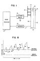
- FIG. 1 is a block diagram illustrating the various components which comprise the closed loop system.
- a thermal print head structure 12 comprising a ceramic substrate 22 and a metal heat sink 20 is operated through a suitable interface circuit 15 shown in Fig. 1 as connecting a plurality of interconnecting lines 17 comprising power, ground, serial data line, clock, latch, and thermistor temperature sensor lines extending between the printhead 12 and the control microprocessor 14.
- the printhead elements 24 are shown in end view and will customarily be controlled by a plurality of on board transistors, one for each individual thermal print head element, which are in turn operated under control of a data processing system and suitable data storage device such as registers and flip flops.
- a temperature sensor 10 embedded in the thermal print head structure 12 flush with the ceramic substrate 22 indicates to a control microprocessor 14 the present temperature of the thermal print head structure 12. If this temperature exceeds a predetermined limit specified in a read-only memory of the microprocessor 14, the microprocessor sends an "on" command to an electronic switch 16, which activates a thermoelectric heat pump 18. The thermoelectric heat pump then remains on, cooling the thermal print head structure 12, until the temperature sensed by the sensor 10 drops below the value which is preset in the read-only memory of the microprocessor 14, whereupon the microprocessor sends an "off" command to the electronic switch 16, which in turn causes the thermoelectric heat pump 18 to cease operation.
- thermoelectric heat pump constitutes an important aspect of the present invention, a further description of this device is believed to be in order.
- Thermoelectric heat pumps are solid-state devices with no moving parts. With a suitable electrical power input, they pump heat from one side of the device to the other. Available in a variety of shapes and sizes, including some sufficiently small to fit on an integrated circuit chip, they provide a means for cooling objects well below ambient temperatures.
- Thermoelectric heat pumps operate upon the principle of the Peltier effect. Briefly stated, this is that the passage of an electrical current through the junction of two dissimilar conductors can either cool or heat the junction, depending upon the direction of the current. Heat generation or absorption are proportional to the magnitude of the current and are dependent upon the temperature of the junction.
- thermoelectric module acts like a simple thermocouple.
- a temperature gradient maintained across the device creates a potential across its terminals which is proportional to the temperature differential. If the temperature differential is maintained, and if the device is connected to an electrical load, power is generated. If, instead, the device is connected to a DC source, heat will be absorbed at one end of the thermoelectric module, cooling it, while heat is rejected at the other end, where the temperature increases. Reversing the current flow reverses the flow of heat, so that the module can generate electrical power, or, depending upon how it is connected to external circuitry, heat or cool an object.
- thermoelectric heat pump In determining the choice of a thermoelectric heat pump, the two key variables which must be known are, first, the quantity of heat which will be generated by the active thermal print head heat source, and, second, the maximum temperature difference which will exist between the cooled thermal print head and the ambient environment.
- the thermal print head employed includes 320 electro-resistive elements, of which no more than 196 elements may operate simultaneously at any one time; for which the power dissipation is 0.85 watts per element; and for which the useful power transmission efficiency is 90%. A ten percent total internal power consumption of approximately 16.7 watts would thus be expected.
- thermoelectric heat pump must pump heat from the thermal printhead heat sink to the thermal printhead carrier frame.
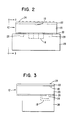
- the thermal printhead 12 shown there includes a heat sink 20 of suitable material, such as aluminum; a ceramic layer 22 containing a line of resistive elements 24, and a temperature sensor 10.
- the thermal printhead 12 is secured to a thermal printhead carrier frame 26 by suitable fastening means such as projections 28 which extend from the heat sink 20 and are engaged in apertures in the frame 26.
- thermoelectric heat pumps 18 may be attached directly to the back of the heat sink 20 in any suitable manner. It may, for example, be pressure clamped between the heat sink 20 and the frame 26, in which case the flatness of the heat sink 20 should be better than plus or minus 0.025 mm (0.001 inch). Alternatively, the heat pump 18 may be epoxied or soldered to the back of the heat sink 20.
- Heat leakage increases proportionately with a cooled object's surface area and decreases proportionately as the thickness of isolating insulation increases.
- the overall rate of change of heat leakage is also dependent upon the temperature differential between the cold and hot surfaces. Therefore in determining the total heat load which a thermoelectric heat pump must transport, not only the active heat source of the thermal print head elements must be considered, but also the heat leakage associated with a specific mechanical configuration.
- a total active heat load Q c of 16.7 watts for the illustrated embodiment is expected.
- a heat leakage of approximately 3.3 watts is estimated, producing a total heat load Q CH of 20 watts.
- thermoelectric heat pump Using the previously assumed temperature differential of 20 degrees C, it is now required to determine the thermoelectric heat pump's operating current and voltage, the number of thermoelectric heat pumps needed, and the amount of heat rejected, Q H , which is the arithmetic sum of the transported heat load Q CH and the input electrical power dissipated in the heat pump.
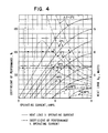
- Fig. 4 illustrates a typical performance chart for a commercially available thermoelectric heat pump. This chart shows the relationship between the heat absorbed at the cold side, Q c , versus operating current. The chart also shows the thermoelectric heat pump's coefficient of performance, COP, versus operating current. The running variable is the difference in temperature between the hot and cold sides. Note that COP is defined as the ratio of Q CH to electrical power in, and can therefore be greater than 100 percent, since the electrical power is used primarily to transport heat.
- thermoelectric heat pump For the preferred embodiment in which Q ⁇ H equals 20 watts, and in which the temperature differential equals 20 degrees C, it is noted that a single thermoelectric heat pump could not handle the entire load, since the maximum heat load transportable by this heat pump at a temperature differential of 20 degrees C is approximately 12 watts. Accordingly, more than one thermoelectric heat pump is required to transport the heat load Q c . Space constraints in the illustrated embodiments of the thermal print head allow no more than three heat pumps 18 to reside at the rear of the thermal print head 12.
- each pump 18 must pump at least half of (Q c + HEAT LEAK) equals Q CT .
- Q c equals Q CT /2, equals 20/2, equals 10 watts.
- Q c the total electrical power consumed by the two pumps is P equals (Q c /COP) N, equals (10/0.65)2, equals 30.77 watts.
- V the two modules connected electrically in series, V equals P/I, equals 30.77/5.6, equals 5.5 volts.
- the total heat rejection is QH equals (Q c x N) + P, equals 10 x 2 + 30.77, equals 50.77 watts.
- Required thermal resistance of the heat sink equals (TH-TA)/QH, equals (50-40)-/50.77, equals 0.197 degrees C per watt.
- Q c QCT/3, equals 20/3, equals 6.67 watts.
- I 3.75 amps; also from Fig. 4, COP equals 101 percent.
- P equals (6.67/1.01)3, equals 19.8 watts.
- V equals 19.8/3.75 equals 5.3 volts.
- QH equals 6.67 x 3 + 19.8, equals 39.8 watts.
- Required thermal resistance of the heat sink equals (50-40)/39.8, equals 0.251 degrees C per watt. It will thus be seen that the disadvantage in utilizing a third heat pump is a reduction in operating current by 1.85 amperes and a 10 watt drop in dissipated power. Requirements for the thermoelectric heat pump are thus for a 5.3 volt source capable of providing 3.75 amperes of current.
- the ambient temperature is not measured. Instead, a worst case temperature differential of 20 degrees C is assigned.
- the thermoelectric heat pumps 18 are simply turned on until the temperature monitored internally in the thermal print head 12 drops below a predetermined value.
- thermoelectric heat pump can control the reference temperature of a thermal print head.
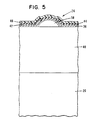
- Fig. 5 is a cross-sectional view of a typical thermal print head element 24.
- a thermal printhead electroresistive element 36 which may be fabricated from Ta 2 N, is positioned above a hemispherical raised partially glazed portion 38, which may be of glass, of a substrate 40, which may be of 96 percent A1 2 0 3 .
- the substrate 40 in turn is bonded to the heat sink 20, which may be of aluminum.
- An aluminum electrode lead 42 is bonded to the element 36, and a first protective layer 44 of Si0 2 is placed thereover, with a second protective layer 46 of Ta 2 0 5 being placed over the layer 44.
- Each electroresistive element 24 of the thermal printhead 12 has an area which is substantially equal to, or a sub-multiple of, the desired incremental area of each character segment to be printed.
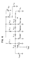
- the element area referred to above therefore has a certain thermal mass which may be modelled in the analog circuit representation of Fig. 6 as an electrical circuit capacitor designated as C ElEMENT .
- the constant electrical current which is passed through the element 24 for the duration of the burn period is modelled in Fig. 6 as a current source I BURN .
- the heat pulse generated by the current source is transmitted to the receiving document and/or thermal transfer ribbon and lost to some extent to the surrounding air, and is also conducted through the thermal resistance separating the element 24 and the substrate 40 through to the thermal mass of the substrate 40.
- the boundary between the thermal element mass and the outside air is represented in Fig. 6 as electrical resistor R E .
- A, E-A representing element to air.
- the boundary between the thermal element mass and the document is represented in Fig.
- the heat which is conducted through to the glaze substrate 40 is further conducted through the thermal resistance between the substrate 40 and the heat sink 20, and lost to the surrounding air.
- the thermal resistance between the substrate 40 and the heat sink 20 is modelled by an electrical resistor R s . H , the S-H representing substrate to heatsink.
- the boundary between the substrate and the surrounding air is represented in Fig. 6 as electrical resistor R S -A, the S-A representing substrate to air.
- the thermal mass of the heat sink 20 is represented in Fig. 6 by a capacitor C HEATSINK .
- the heat sink 20 will radiate some of its absorbed heat to the surrounding air, as modelled by the electrical resistor R H .
- A the H-A representing heat sink to air.
- an electrical resistor R H _ F (H-F representing heat sink to frame), is not featured in the analog circuit representation of Fig. 6.
- the surrounding air temperature is modelled in Fig. 6 by a varying voltage source VAIR.
- the heat sink 20 will either be connected to a passive (turned off) thermoelectric heat pump 18 which is modelled by a capacitor C TE and a resistor R TE -A -(referring to heat pump to air) or will be connected to an active (turned on) thermoelectric heat pump 18 modelled by a reverse polarity battery V TE and a resistor R H-TE (referring to heat sink to heat pump).
- a two-position switch 50 in Fig. 6 represents the capability of selection, in inclusion of the battery V TE representing an active heat pump 18.
- the thermal mass of the receiving thermal paper or thermal transfer ribbon is represented in Fig. 6 by a capacitor C PAPER .
- the objective, in terms of the representation of Fig. 6, is to produce sufficient charge (heat) to exceed the threshold voltage V THRESHOLD , representing the transfer or print temperature.
- the discharge or cooling time (that is, the time taken to return to ambient temperature conditions) is generally longer than the burn time.
- Reference to the diagram of Fig. 6 will show that the capacitor C ELEMENT is charged directly by the external current source 1 13URN , whereas once 113URN is removed during the COOL period, C ELEMENT must discharge through the effective impedance of the entire system, which, of course, has a much longer time constant.
- Fig. 7 illustrates one system control circuit implementation which can be derived from the block diagram of Fig. 1.
- the temperature sensor 10 may suitably be implemented as a 10,000-ohm thermistor which is placed in a circuit which also includes a 10,000-ohm fixed resistor 52 and which extends from a plus 5-volt source of potential to a ground connection. From a point between the thermistor 10 and the resistor 52, a path extends to an analog-to-digital converter 54, which may be of type ADC0809, manufactured by National Semiconductor Corp. of Santa Clara, California.
- the analog-to-digital converter 54 has appropriate terminals connected to + 5 volts and ground, and also has outputs 56 coupled to the microprocessor 14, which may be type 8051, manufactured by Intel Corporation, Santa Clara, California, for providing digital data thereto after said data has been received in analog form from the thermistor 10.
- a START CONVERT line 58 extends from the microprocessor 14 to the analog-to-digital converter 54, so that the microprocessor 14 can periodically monitor the thermistor 10, to determine when the established 30 degree C reference temperature has been exceeded.
- the 30 degree C reference temperature may be stored in a suitable memory location in the microprocessor for comparison with the temperature sensed by the thermistor 10.
- the microprocessor transmits signals over lines 60 to cause the output of a flip-flop 62 to be switched to a "low" level.
- the flip-flop 62 may be of type 74C74, manufactured by Texas Instruments, Dallas, Texas, and has appropriate terminals connected to a source of plus 12 volts and to ground.
- the output of the flip-flop 62 is connected to a 1000-ohm resistor 64 and an LED 66, which is included for display purposes, to the negative input of a solid state relay 68, which may be of type IR S218, manufactured by International Rectifier, of EI Segundo, California.
- the positive terminal of the relay 68 is connected to a source of plus 12-volt potential, and the two AC terminals of said relay are connected to the operating circuit of the secondary coil 70 of a transformer 72.
- Said operating circuit also contains a fuse 74 and terminals 76 which are applied to a source of 110 volts AC, 60 Hz.
- Two diodes 80 and 82 rectify the low voltage AC waveform which appears on the secondary coil 78 of the transformer 72 when the solid state relay 68 is activated by the flip-flop 62. This rectification produces a "constant" 5.5 volts potential at a current of 4 amperes, which is applied across the three thermoelectric heat pumps 18 to cause them to operate to cool the thermal printhead 12.
- the next monitoring of the thermistor 10 will show that the temperature has dropped below 30 degrees C, and the microprocessor 14 will then trigger the flip-flop 62 to turn off the solid state relay 68, and thereby halt operation of the thermoelectric heat pumps 18.
- thermoelectric heat pumps 18 Other more sophisticated circuits may be considered for the control of the thermoelectric heat pumps 18, should it be desired to supply only the power necessary to transport the heat from the thermal print head 12 out to the ambient environment.
- This might take the form of an adjustable voltage regulator along with a chopper pulsed HEX-FET electronic switch to regulate the current flow.
- the circuit of Fig. 7 is sufficient to accomplish the needed cooling of the thermal printhead 12.
- thermoelectric heat pump It would also be possible to use a circuit similar to that of Fig. 7 to heat a thermal printhead if the surrounding ambient air is too cool or if the thermal printhead temperature drops below some specified reference zone. Another branch of the same circuit could be employed to cool the thermal printhead should its temperature rise beyond an established point. It will be recalled that heating of the thermal printhead through the thermoelectric heat pumps merely requires a polarity reversal of the drive circuit which is used for cooling of the thermal printhead by the thermoelectric heat pump.
Landscapes
- Electronic Switches (AREA)
- Accessory Devices And Overall Control Thereof (AREA)
Claims (8)
Applications Claiming Priority (2)
| Application Number | Priority Date | Filing Date | Title |
|---|---|---|---|
| US06/855,271 US4797837A (en) | 1986-04-24 | 1986-04-24 | Method and apparatus for thermal printer temperature control |
| US855271 | 1997-05-14 |
Publications (2)
| Publication Number | Publication Date |
|---|---|
| EP0243046A1 EP0243046A1 (de) | 1987-10-28 |
| EP0243046B1 true EP0243046B1 (de) | 1991-06-12 |
Family
ID=25320811
Family Applications (1)
| Application Number | Title | Priority Date | Filing Date |
|---|---|---|---|
| EP87303119A Expired EP0243046B1 (de) | 1986-04-24 | 1987-04-09 | Verfahren und Vorrichtung zur Temperatursteuerung eines Wärmedruckers |
Country Status (5)
| Country | Link |
|---|---|
| US (1) | US4797837A (de) |
| EP (1) | EP0243046B1 (de) |
| JP (1) | JPS62257864A (de) |
| CA (1) | CA1279692C (de) |
| DE (2) | DE3770684D1 (de) |
Families Citing this family (22)
| Publication number | Priority date | Publication date | Assignee | Title |
|---|---|---|---|---|
| JPS63134289A (ja) * | 1986-11-26 | 1988-06-06 | Canon Inc | 熱転写記録方法 |
| US5118964A (en) * | 1990-09-26 | 1992-06-02 | At&T Bell Laboratories | Thermo-electric temperature control arrangement for laser apparatus |
| US5168284A (en) * | 1991-05-01 | 1992-12-01 | Hewlett-Packard Company | Printhead temperature controller that uses nonprinting pulses |
| US5237338A (en) * | 1991-08-05 | 1993-08-17 | Eastman Kodak Company | Is-enthalpic control of a thermal printing head |
| US5211493A (en) * | 1992-06-05 | 1993-05-18 | Eastman Kodak Company | Cooling system for a thermal printing head |
| US5622897A (en) * | 1993-05-20 | 1997-04-22 | Compaq Computer Corporation | Process of manufacturing a drop-on-demand ink jet printhead having thermoelectric temperature control means |
| US5623292A (en) * | 1993-12-17 | 1997-04-22 | Videojet Systems International, Inc. | Temperature controller for ink jet printing |
| DE69401573T2 (de) * | 1994-03-09 | 1997-06-26 | Agfa Gevaert Nv | Thermodrucker mit Temperaturabschätzung in Echtzeit |
| US6193349B1 (en) * | 1997-06-18 | 2001-02-27 | Lexmark International, Inc. | Ink jet print cartridge having active cooling cell |
| WO2001032423A1 (en) | 1999-10-29 | 2001-05-10 | Daniel Bostrack | Print cylinder cooling system |
| EP1431045A1 (de) * | 2002-12-17 | 2004-06-23 | Agfa-Gevaert | Modellierungsverfahren zur Berücksichtigung der Thermokopftemperatur und der Raumtemperatur |
| US9236639B2 (en) * | 2003-12-18 | 2016-01-12 | GM Global Technology Operations LLC | Thermoelectric methods to control temperature of batteries |
| US20060028182A1 (en) * | 2004-07-23 | 2006-02-09 | Jihui Yang | Thermoelectric methods to control temperature of batteries |
| JP4670410B2 (ja) | 2005-03-16 | 2011-04-13 | ソニー株式会社 | サーマルヘッドプリンタ及びサーマルヘッドプリンタの印画方法 |
| US7330201B2 (en) * | 2005-09-28 | 2008-02-12 | Eastman Kodak Company | Thermal printer and method for operating same |
| WO2008036220A2 (en) * | 2006-09-18 | 2008-03-27 | Zink Imaging, Inc. | Thermal printer with auxiliary heat sink and methods for printing using same |
| US8979237B2 (en) * | 2009-12-25 | 2015-03-17 | Seiko Epson Corporation | Recording head control method and dot impact printer |
| US8395646B2 (en) | 2011-06-14 | 2013-03-12 | Rohm Semiconductors USA, LLC | Thermal printer with energy save features |
| US8411121B2 (en) | 2011-06-14 | 2013-04-02 | Rohm Semiconductor USA, LLC | Thermal printhead with optimally shaped resistor layer |
| US8305411B1 (en) * | 2011-06-14 | 2012-11-06 | Rohm Semiconductor USA, LLC | Thermal printhead with temperature regulation |
| CN113815316B (zh) * | 2020-11-26 | 2022-10-04 | 山东华菱电子股份有限公司 | 基于差异化恒流加热的热敏打印头加热控制方法及装置 |
| CN114872470B (zh) * | 2022-04-07 | 2023-09-22 | 厦门汉印电子技术有限公司 | 一种打印方法、装置、打印设备及存储介质 |
Family Cites Families (20)
| Publication number | Priority date | Publication date | Assignee | Title |
|---|---|---|---|---|
| US3409902A (en) * | 1966-05-27 | 1968-11-05 | Texas Instruments Inc | High speed thermal printer |
| US3577137A (en) * | 1968-12-31 | 1971-05-04 | Texas Instruments Inc | Temperature compensated electronic display |
| JPS52141526A (en) * | 1975-10-27 | 1977-11-25 | Seiko Epson Corp | Voltage and temperature compensating control of thermal printer |
| US4262188A (en) * | 1979-01-02 | 1981-04-14 | Hewlett-Packard Company | Method and apparatus for improving print quality of a thermal printer |
| JPS55117673A (en) * | 1979-03-03 | 1980-09-10 | Canon Inc | Thermal recording device |
| US4284876A (en) * | 1979-04-24 | 1981-08-18 | Oki Electric Industry Co., Ltd. | Thermal printing system |
| JPS562175A (en) * | 1979-06-18 | 1981-01-10 | Mitsubishi Electric Corp | Heat controlling method of heat-sensitive head |
| US4305080A (en) * | 1979-07-18 | 1981-12-08 | International Business Machines Corporation | Compensating driver circuit for thermal print head |
| US4347518A (en) * | 1979-09-04 | 1982-08-31 | Gould Inc. | Thermal array protection apparatus |
| JPS5745076A (en) * | 1980-09-01 | 1982-03-13 | Fuji Xerox Co Ltd | Heat-sensitive recording head |
| US4391535A (en) * | 1981-08-10 | 1983-07-05 | Intermec Corporation | Method and apparatus for controlling the area of a thermal print medium that is exposed by a thermal printer |
| JPS58160169A (ja) * | 1982-03-18 | 1983-09-22 | Shinko Electric Co Ltd | サ−マルプリンタ |
| JPS58188676A (ja) * | 1982-04-30 | 1983-11-04 | Sato :Kk | 感熱印字装置の温度制御方式 |
| JPS5948169A (ja) * | 1982-09-13 | 1984-03-19 | Fuji Xerox Co Ltd | サ−マルヘツド駆動制御装置 |
| US4449033A (en) * | 1982-12-27 | 1984-05-15 | International Business Machines Corporation | Thermal print head temperature sensing and control |
| US4574293A (en) * | 1983-05-23 | 1986-03-04 | Fuji Xerox Co., Ltd. | Compensation for heat accumulation in a thermal head |
| JPS60122184A (ja) * | 1983-12-06 | 1985-06-29 | Citizen Watch Co Ltd | インパクトプリンタにおける印字ヘツドの温度制御方法 |
| US4542281A (en) * | 1984-03-02 | 1985-09-17 | Combustion Engineering, Inc. | Thermal printer contrast control |
| DE3466959D1 (en) * | 1984-03-24 | 1987-12-03 | Honeywell Inf Systems | Cooling apparatus for dot matrix impact print head |
| JPH0712688B2 (ja) * | 1985-05-10 | 1995-02-15 | 株式会社リコー | 熱記録装置 |
-
1986
- 1986-04-24 US US06/855,271 patent/US4797837A/en not_active Expired - Lifetime
-
1987
- 1987-01-08 CA CA000526930A patent/CA1279692C/en not_active Expired - Lifetime
- 1987-04-09 DE DE8787303119T patent/DE3770684D1/de not_active Expired - Lifetime
- 1987-04-09 EP EP87303119A patent/EP0243046B1/de not_active Expired
- 1987-04-09 DE DE198787303119T patent/DE243046T1/de active Pending
- 1987-04-22 JP JP62097678A patent/JPS62257864A/ja active Pending
Also Published As
| Publication number | Publication date |
|---|---|
| CA1279692C (en) | 1991-01-29 |
| EP0243046A1 (de) | 1987-10-28 |
| DE3770684D1 (de) | 1991-07-18 |
| US4797837A (en) | 1989-01-10 |
| JPS62257864A (ja) | 1987-11-10 |
| DE243046T1 (de) | 1988-05-19 |
Similar Documents
| Publication | Publication Date | Title |
|---|---|---|
| EP0243046B1 (de) | Verfahren und Vorrichtung zur Temperatursteuerung eines Wärmedruckers | |
| US4113391A (en) | Method for controlling voltage and providing temperature compensation in a thermal printer | |
| US3577137A (en) | Temperature compensated electronic display | |
| EP0421353A2 (de) | Steuervorrichtung für Thermodrucker | |
| JPH05193179A (ja) | 熱印刷ヘッド制御装置 | |
| JP2914128B2 (ja) | サーマルヘッドの発熱体の駆動装置 | |
| EP0718107B1 (de) | Wärmekopfgerät | |
| JPS5830839B2 (ja) | サ−マルプリンタの通電パルス印加方法 | |
| JPS60201971A (ja) | サ−マルドツト式印字装置 | |
| JP3067931B2 (ja) | サーマルヘッドの予熱方法 | |
| JP2939653B2 (ja) | 発熱抵抗体の駆動方法 | |
| JP2729164B2 (ja) | 電池保温プリンタ | |
| JP2546148B2 (ja) | 温度制御回路 | |
| JPS63118273A (ja) | サ−マルヘツド加熱法 | |
| JPH0768824A (ja) | サーマルヘッドの温度制御装置 | |
| JPH02241762A (ja) | 小型サーマルプリンタ | |
| JPH0366751U (de) | ||
| JPH02281969A (ja) | サーマルヘッド | |
| JPS60248364A (ja) | サ−マルヘツド | |
| JP2521453B2 (ja) | サ−マルヘツド | |
| JPS5638279A (en) | Thermal recording device | |
| JPH0211347A (ja) | サーマルヘッドの駆動制御方式 | |
| JPH04197754A (ja) | インクジェット記録装置の温度制御装置 | |
| JPH04201460A (ja) | サーマルヘッドの恒温装置 | |
| JPH04369562A (ja) | サーマルプリンタ装置 |
Legal Events
| Date | Code | Title | Description |
|---|---|---|---|
| PUAI | Public reference made under article 153(3) epc to a published international application that has entered the european phase |
Free format text: ORIGINAL CODE: 0009012 |
|
| AK | Designated contracting states |
Kind code of ref document: A1 Designated state(s): DE FR GB |
|
| EL | Fr: translation of claims filed | ||
| 17P | Request for examination filed |
Effective date: 19880314 |
|
| DET | De: translation of patent claims | ||
| 17Q | First examination report despatched |
Effective date: 19890825 |
|
| GRAA | (expected) grant |
Free format text: ORIGINAL CODE: 0009210 |
|
| AK | Designated contracting states |
Kind code of ref document: B1 Designated state(s): DE FR GB |
|
| REF | Corresponds to: |
Ref document number: 3770684 Country of ref document: DE Date of ref document: 19910718 |
|
| ET | Fr: translation filed | ||
| PLBE | No opposition filed within time limit |
Free format text: ORIGINAL CODE: 0009261 |
|
| STAA | Information on the status of an ep patent application or granted ep patent |
Free format text: STATUS: NO OPPOSITION FILED WITHIN TIME LIMIT |
|
| 26N | No opposition filed | ||
| REG | Reference to a national code |
Ref country code: GB Ref legal event code: IF02 |
|
| PGFP | Annual fee paid to national office [announced via postgrant information from national office to epo] |
Ref country code: GB Payment date: 20020321 Year of fee payment: 16 |
|
| PGFP | Annual fee paid to national office [announced via postgrant information from national office to epo] |
Ref country code: FR Payment date: 20020417 Year of fee payment: 16 |
|
| PGFP | Annual fee paid to national office [announced via postgrant information from national office to epo] |
Ref country code: DE Payment date: 20020605 Year of fee payment: 16 |
|
| PG25 | Lapsed in a contracting state [announced via postgrant information from national office to epo] |
Ref country code: GB Free format text: LAPSE BECAUSE OF NON-PAYMENT OF DUE FEES Effective date: 20030409 |
|
| PG25 | Lapsed in a contracting state [announced via postgrant information from national office to epo] |
Ref country code: DE Free format text: LAPSE BECAUSE OF NON-PAYMENT OF DUE FEES Effective date: 20031101 |
|
| GBPC | Gb: european patent ceased through non-payment of renewal fee |
Effective date: 20030409 |
|
| PG25 | Lapsed in a contracting state [announced via postgrant information from national office to epo] |
Ref country code: FR Free format text: LAPSE BECAUSE OF NON-PAYMENT OF DUE FEES Effective date: 20031231 |
|
| REG | Reference to a national code |
Ref country code: FR Ref legal event code: ST |