EP0243048A1 - Knife sharpeners - Google Patents
Knife sharpeners Download PDFInfo
- Publication number
- EP0243048A1 EP0243048A1 EP87303133A EP87303133A EP0243048A1 EP 0243048 A1 EP0243048 A1 EP 0243048A1 EP 87303133 A EP87303133 A EP 87303133A EP 87303133 A EP87303133 A EP 87303133A EP 0243048 A1 EP0243048 A1 EP 0243048A1
- Authority
- EP
- European Patent Office
- Prior art keywords
- blade
- sharpening device
- knife
- sharpening
- spring
- Prior art date
- Legal status (The legal status is an assumption and is not a legal conclusion. Google has not performed a legal analysis and makes no representation as to the accuracy of the status listed.)
- Withdrawn
Links
Images
Classifications
-
- B—PERFORMING OPERATIONS; TRANSPORTING
- B24—GRINDING; POLISHING
- B24B—MACHINES, DEVICES, OR PROCESSES FOR GRINDING OR POLISHING; DRESSING OR CONDITIONING OF ABRADING SURFACES; FEEDING OF GRINDING, POLISHING, OR LAPPING AGENTS
- B24B3/00—Sharpening cutting edges, e.g. of tools; Accessories therefor, e.g. for holding the tools
- B24B3/36—Sharpening cutting edges, e.g. of tools; Accessories therefor, e.g. for holding the tools of cutting blades
-
- B—PERFORMING OPERATIONS; TRANSPORTING
- B24—GRINDING; POLISHING
- B24D—TOOLS FOR GRINDING, BUFFING OR SHARPENING
- B24D15/00—Hand tools or other devices for non-rotary grinding, polishing, or stropping
- B24D15/06—Hand tools or other devices for non-rotary grinding, polishing, or stropping specially designed for sharpening cutting edges
- B24D15/08—Hand tools or other devices for non-rotary grinding, polishing, or stropping specially designed for sharpening cutting edges of knives; of razors
- B24D15/081—Hand tools or other devices for non-rotary grinding, polishing, or stropping specially designed for sharpening cutting edges of knives; of razors with sharpening elements in interengaging or in mutual contact
-
- B—PERFORMING OPERATIONS; TRANSPORTING
- B24—GRINDING; POLISHING
- B24D—TOOLS FOR GRINDING, BUFFING OR SHARPENING
- B24D15/00—Hand tools or other devices for non-rotary grinding, polishing, or stropping
- B24D15/06—Hand tools or other devices for non-rotary grinding, polishing, or stropping specially designed for sharpening cutting edges
- B24D15/08—Hand tools or other devices for non-rotary grinding, polishing, or stropping specially designed for sharpening cutting edges of knives; of razors
- B24D15/084—Hand tools or other devices for non-rotary grinding, polishing, or stropping specially designed for sharpening cutting edges of knives; of razors the sharpening elements being fitted to knife sheaths, holders or handles
Definitions
- the invention relates to knife sharpeners which are carried within a scabbard or housing in which a blade of a knife is received when not in use.
- Such knife sharpeners include a sharpening device which is engaged by a blade edge when the blade is inserted into or removed from the scabbard or housing.
- the sharpening device maintains a permanent operative position i.e. it engages the blade edge with a sharpening action on every occasion when the blade is inserted into or removed from the scabbard or housing.
- a knife sharpener of the kind comprising a guideway for receiving a knife blade and a sharpening device urged by a spring into a blade edge engaging position, characterised in that the sharpening means are releasably latchable against the action of said spring in an inoperative position.
- the sharpening device can be rendered ineffective and only engage with the blade when sharpening is required.
- the sharpening device In known knife sharpeners where the sharpening device invariably engages a knife blade inserted into or removed from the associated housing or scabbard, the sharpening device generally performs a dual function of both sharpening the edge and retaining the knife blade within the sharpener.
- a knife sharpener of the kind comprising a guideway for engaging a back edge of a knife blade on insertion of the blade into the sharpener and a sharpening device for sharpening an edge of the knife blade, characterised in that the sharpening device is selectively positionable to engage a blade of the knife inserted into the sharpener or to be inoperative, and a blade retaining device is provided for urging an inserted blade into engagement with the guideway to retain the blade within the sharpener when the sharpening device is in said inoperative position.
- the knife retaining device in combination with the sharpening device which can be positioned for engagement with a knife blade, or rendered inoperative, the knife blade is reliably retained within the sharpener even when the sharpening device is rendered inoperative.
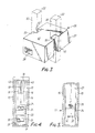
- the knife sharpener comprises a housing 10, a sharpening device 11 and a blade retaining device 12.
- the housing 10 has a generally rectangular entrance 13 (see Fig.4) and exit 14 formed between side walls 15 and upper and lower walls 16 and 17 respectively.
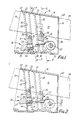
- a guideway 18 (Fig.4) is formed within the housing 10 firstly between two angled members 43 and then between two parallel members 19, with both sets of members being disposed on opposite sides of a plane including the centre line of the housing 10 and parallel to the side walls 15 of the housing 10.
- the members 43, 19 depend from the upper wall 16 of the housing which thus forms a base to the guideway.
- Each groove 20, 21 is formed by a pair of parallel flanges 22 extending from an associated side wall 15 of the housing 10.
- the grooves of each pair 20 or 21 extend downwardly and inwardly of the housing 10 (see Figs.1 and 2).
- the pairs of grooves 20, 21 are parallel to one another but are spaced apart (see Fig.1).
- the first pair of grooves 20 receive respective edges of the sharpening device 11, which is thus constrained to rectilinear sliding movement between the upper and lower ends of the associated grooves 20.
- the sharpening device 11 comprises a carrier 23 having on its upper surface 24 a pair of carbide cutters 25 which form a V-notch between them for receipt of an edge of a knife blade to be sharpened.
- the carrier 23 is provided with a central aperture within which is mounted a detent 26 (see Figure 3) formed with a pair of side grooves 40 ( Figure 3) which engage corresponding ones 22 of each pair of flanges forming the associated grooves 20.
- the detent 26 has an upper surface 41. An end of the detent 26 adjacent the entrance to the housing forms a manually operable button 27.
- the opposite end of the detent 26 is formed with an aperture 28 which receives one end of a spiral spring 30 whose other end is fixed to a mounting 29 provided in the housing 10 on a side of the sharpening device 11 opposite to the entrance 13 of the housing 10.
- the spring 30 is bowed in stress so that the detent 26 and hence the sharpening device are urged upwardly and outwardly in the associated grooves 20.
- the two groove forming flanges 22 adjacent the entrance 13 of the housing 10 have respective inner and outer surfaces 31, 32 which are parallel to give the flanges, in the upper parts of the flanges 22, a constant wider thickness. However, towards their lower ends, these flanges 22 are of reduced thickness (see Figures 1 and 2) with the reduced thickness portion 44 being connected to the increased thickness portion by a step 33, whose function will be described below.
- the mounting of the detent 26 in the carrier 23 is such as to allow limited relative movement between the detent 26 and the carrier 23, again for a purpose to be described below.
- the other pair of grooves 21 receive corresponding edges of the blade retaining device 12 see also Figure 5), which is thus restrained for sliding movement between the upper and lower ends of the grooves 21.
- the blade retaining device 12 comprises a block 34 on which are mounted three pins 35 which together form a V-notch for receipt of a blade edge.
- the angle of the V-notch is less than the angle of the carbide cutters 25.
- the block 34 is cut away to one side in order to prevent any interference by the block 34 with the spring 30 for the sharpening device 11.
- the housing 10 may be mounted at an open end of a scabbard (not shown) with the entrance 13 to the housing forming an entrance to the scabbard.
- the housing 10 can be mounted alone on a wall or at any other convenient situation.
- the sharpening device 11 When a blade edge (shown in Figures 1 and 2 in broken line at 38) of a knife blade (shown in Figures 1 and 2 in broken line at 39) is to be sharpened, the sharpening device 11 is in the blade engaging position shown in Figure 2.
- the blade 39 is inserted into the housing entrance 13 with a back edge 40 of the blade being guided by the guideway 18 and the blade edge 38 at the blade tip engaging in the V-notch formed by the carbide cutters 25. Continued insertion of the blade 39 forces the sharpening device 11 downwards against the action of the associated spring 30.
- the tip of the blade then engages with the sides of the V-notch formed by the pins 35 (since the angle of the V-notch is less than the angle of the carbide cutters and hence less than the angle of the blade edge) and forces the blade retaining device 12 downwardly against the action of the second spring 37 on continued insertion of the blade 39. Insertion is then further continued until the end of the blade handle (not shown) abuts the housing 10.
- the sharpening device 11 may be rendered inoperable. This is done by pressing downwardly the button 27 on the detent 26, to slide the sharpening device 11 downwardly in the associated grooves 20.
- the spring 30, which provides not only a force in a direction along the grooves 20, but also provides a force at right angles to that direction, causes the detent 26 to slide relative to the carrier 23 to engage the upper surface 41 of the detent 26 under the step 33 in the flanges 22 and to cause the detent to engage against the reduced thickness portions 44 of the flanges 22.
- the back edge 40 of the blade will, as before, engage in the guideway 18.
- the tip of the blade will first engage the blade retaining device 12, passing through the V-notch formed by the pins 35. This will force the blade retaining device 12 downwardly against the action of the second spring 37. There will be no sharpening action.
- the blade 39 is fully inserted, it is retained in the housing 10 by the force of the second spring 37 acting on the blade retaining device 12 to hold the blade between this device and the upper wall 16 forming the base of the guideway 18. This will prevent the knife falling out of the housing 10 and the scabbard, where such is provided.
- the button 27 formed on the detent 26 is pressed, to cause the detent 26 to perform a reverse sliding movement, which unlatches the detent 26 from the step 33 and allows the first spring 30 to push the sharpening device 11 up the guideway up towards the upper ends of the associated grooves 20.
- the carbide cutters 25 can be engaged by the edge 38 of a blade 39 inserted into the housing 10.
- the knife sharpener described above with reference to the drawings thus provides a sharpening device 11 which can be rendered inoperative, as desired. This lengthens the life of the blade by ensuring that sharpening is effected only when required. This also lengthens the life of the carbide cutters 25.
- the knife sharpener retains the blade relatively to the sharpener even when the sharpening device 11 is rendered inoperative.
- the rendering of the sharpening device inoperative does not affect the use of the housing 10, and any associated scabbard, to hold the blade.
- leaf springs it is not necessary to use leaf springs to apply the required spring force. Any suitable spring may be required which performs the necessary action.
- the blade retaining device may be urged by a helical spring or a leaf spring or a suitably arranged torsion spring.
- Alternative springs may be used on the sharpening device as well.
- the two pairs of grooves 20, 21 need not be parallel, they could converge towards the top of the housing 10.
- the grooves 20 accommodating the sharpening means could be curved to ensure accurate orientation of the carbide cutters 25 relative to the blade edge 38 towards the tip of a knife.
Landscapes
- Engineering & Computer Science (AREA)
- Mechanical Engineering (AREA)
- Finish Polishing, Edge Sharpening, And Grinding By Specific Grinding Devices (AREA)
Applications Claiming Priority (2)
| Application Number | Priority Date | Filing Date | Title |
|---|---|---|---|
| GB868610177A GB8610177D0 (en) | 1986-04-25 | 1986-04-25 | Knife sharpeners |
| GB8610177 | 1986-04-25 |
Publications (1)
| Publication Number | Publication Date |
|---|---|
| EP0243048A1 true EP0243048A1 (en) | 1987-10-28 |
Family
ID=10596848
Family Applications (1)
| Application Number | Title | Priority Date | Filing Date |
|---|---|---|---|
| EP87303133A Withdrawn EP0243048A1 (en) | 1986-04-25 | 1987-04-10 | Knife sharpeners |
Country Status (8)
| Country | Link |
|---|---|
| EP (1) | EP0243048A1 (da) |
| JP (1) | JPS62255054A (da) |
| KR (1) | KR870009820A (da) |
| AU (1) | AU7184787A (da) |
| BR (1) | BR8701900A (da) |
| DK (1) | DK210287A (da) |
| GB (1) | GB8610177D0 (da) |
| PT (1) | PT84741B (da) |
Cited By (3)
| Publication number | Priority date | Publication date | Assignee | Title |
|---|---|---|---|---|
| EP0415604A1 (en) * | 1989-08-28 | 1991-03-06 | McPherson's Limited | Blade sharpener |
| WO1996011086A1 (en) * | 1994-10-05 | 1996-04-18 | Mcpherson's Limited | A blade scabbard |
| AU685322B2 (en) * | 1994-10-05 | 1998-01-15 | Mcpherson's Limited | A blade scabbard |
Citations (3)
| Publication number | Priority date | Publication date | Assignee | Title |
|---|---|---|---|---|
| US3774350A (en) * | 1970-12-24 | 1973-11-27 | Wiltshire Cutlery Co Pty | Knife scabbard or holder |
| EP0110661A2 (en) * | 1982-11-24 | 1984-06-13 | McPherson's Limited | Knife sharpener and scabbard |
| EP0185483A2 (en) * | 1984-12-13 | 1986-06-25 | Fiskars Limited | Improvements in or relating to knife sharpeners |
-
1986
- 1986-04-25 GB GB868610177A patent/GB8610177D0/en active Pending
-
1987
- 1987-04-10 EP EP87303133A patent/EP0243048A1/en not_active Withdrawn
- 1987-04-21 JP JP62096348A patent/JPS62255054A/ja active Pending
- 1987-04-22 BR BR8701900A patent/BR8701900A/pt unknown
- 1987-04-22 AU AU71847/87A patent/AU7184787A/en not_active Abandoned
- 1987-04-22 KR KR870003890A patent/KR870009820A/ko not_active Withdrawn
- 1987-04-23 PT PT84741A patent/PT84741B/pt unknown
- 1987-04-24 DK DK210287A patent/DK210287A/da not_active Application Discontinuation
Patent Citations (3)
| Publication number | Priority date | Publication date | Assignee | Title |
|---|---|---|---|---|
| US3774350A (en) * | 1970-12-24 | 1973-11-27 | Wiltshire Cutlery Co Pty | Knife scabbard or holder |
| EP0110661A2 (en) * | 1982-11-24 | 1984-06-13 | McPherson's Limited | Knife sharpener and scabbard |
| EP0185483A2 (en) * | 1984-12-13 | 1986-06-25 | Fiskars Limited | Improvements in or relating to knife sharpeners |
Cited By (4)
| Publication number | Priority date | Publication date | Assignee | Title |
|---|---|---|---|---|
| EP0415604A1 (en) * | 1989-08-28 | 1991-03-06 | McPherson's Limited | Blade sharpener |
| WO1996011086A1 (en) * | 1994-10-05 | 1996-04-18 | Mcpherson's Limited | A blade scabbard |
| AU685322B2 (en) * | 1994-10-05 | 1998-01-15 | Mcpherson's Limited | A blade scabbard |
| US5784786A (en) * | 1994-10-05 | 1998-07-28 | Mcpherson's Limited | Blade scabbard and sharpener |
Also Published As
| Publication number | Publication date |
|---|---|
| KR870009820A (ko) | 1987-11-30 |
| AU7184787A (en) | 1987-10-29 |
| DK210287A (da) | 1987-10-26 |
| BR8701900A (pt) | 1988-02-02 |
| GB8610177D0 (en) | 1986-05-29 |
| PT84741B (en) | 1989-06-08 |
| PT84741A (en) | 1987-05-01 |
| JPS62255054A (ja) | 1987-11-06 |
| DK210287D0 (da) | 1987-04-24 |
Similar Documents
| Publication | Publication Date | Title |
|---|---|---|
| US7175023B2 (en) | Chisel scabbard with removable insert | |
| CN102497957B (zh) | 刀片鞘、刃磨器及刃磨匣 | |
| US3845554A (en) | Knife blade and handle | |
| JP5457334B2 (ja) | 狩猟用及びアジアンナイフのための精密研ぎ器 | |
| US4660287A (en) | Knife with replaceable blade | |
| EP2103386B1 (en) | Two step abrasive sharpener | |
| CA1038628A (en) | Knife sharpener | |
| US6997795B2 (en) | Versatile manual scissor sharpener | |
| NO156119B (no) | Saks-slire med integrert bladsliper. | |
| US5063671A (en) | Kitchen shears with hiding spring | |
| US4815240A (en) | Hand-held skate sharpener | |
| US4869027A (en) | Knife holding and sharpening cassette and knives therefor | |
| SE8307196D0 (sv) | Bladskerpningsinsats for knivsslida | |
| US5893212A (en) | Cigar cutter | |
| JP2002508716A (ja) | 手持ち式かんな削り機械 | |
| US20030077990A1 (en) | Electrical knife sharpening device | |
| EP0243048A1 (en) | Knife sharpeners | |
| US5157879A (en) | Broadhead arrow sharpener | |
| US20070224922A1 (en) | Knife Sharpening Apparatus | |
| US4455736A (en) | Staple removing apparatus | |
| EP0149640B1 (en) | Mat board cutter with knife blade securing safety pin | |
| US6454642B1 (en) | Device for sharpening knives, scissors or other cutting tools | |
| US2624116A (en) | Cutter holder | |
| IE48339B1 (en) | Device for sharpening scissors | |
| US6725549B2 (en) | Sliding sharpening device for pencil with non-circular cross section |
Legal Events
| Date | Code | Title | Description |
|---|---|---|---|
| PUAI | Public reference made under article 153(3) epc to a published international application that has entered the european phase |
Free format text: ORIGINAL CODE: 0009012 |
|
| AK | Designated contracting states |
Kind code of ref document: A1 Designated state(s): AT BE CH DE ES FR GB GR IT LI LU NL SE |
|
| RAP1 | Party data changed (applicant data changed or rights of an application transferred) |
Owner name: FISKARS LIMITED |
|
| STAA | Information on the status of an ep patent application or granted ep patent |
Free format text: STATUS: THE APPLICATION IS DEEMED TO BE WITHDRAWN |
|
| 18D | Application deemed to be withdrawn |
Effective date: 19881102 |
|
| RIN1 | Information on inventor provided before grant (corrected) |
Inventor name: MCPHEE, ALEXANDER |