EP0243345A1 - Support pour l'affichage mobile des représentations publicitaires - Google Patents
Support pour l'affichage mobile des représentations publicitaires Download PDFInfo
- Publication number
- EP0243345A1 EP0243345A1 EP87890085A EP87890085A EP0243345A1 EP 0243345 A1 EP0243345 A1 EP 0243345A1 EP 87890085 A EP87890085 A EP 87890085A EP 87890085 A EP87890085 A EP 87890085A EP 0243345 A1 EP0243345 A1 EP 0243345A1
- Authority
- EP
- European Patent Office
- Prior art keywords
- bearing
- stand according
- base frame
- support shaft
- pendulum
- Prior art date
- Legal status (The legal status is an assumption and is not a legal conclusion. Google has not performed a legal analysis and makes no representation as to the accuracy of the status listed.)
- Granted
Links
- 239000000463 material Substances 0.000 title claims abstract description 11
- 230000000284 resting effect Effects 0.000 claims 1
- 238000013016 damping Methods 0.000 abstract description 5
- 230000002349 favourable effect Effects 0.000 description 3
- 230000005284 excitation Effects 0.000 description 2
- 238000009434 installation Methods 0.000 description 2
- 235000015095 lager Nutrition 0.000 description 2
- NJPPVKZQTLUDBO-UHFFFAOYSA-N novaluron Chemical compound C1=C(Cl)C(OC(F)(F)C(OC(F)(F)F)F)=CC=C1NC(=O)NC(=O)C1=C(F)C=CC=C1F NJPPVKZQTLUDBO-UHFFFAOYSA-N 0.000 description 2
- 239000004576 sand Substances 0.000 description 2
- XLYOFNOQVPJJNP-UHFFFAOYSA-N water Substances O XLYOFNOQVPJJNP-UHFFFAOYSA-N 0.000 description 2
- 239000012267 brine Substances 0.000 description 1
- 239000000969 carrier Substances 0.000 description 1
- 238000003780 insertion Methods 0.000 description 1
- 230000037431 insertion Effects 0.000 description 1
- 238000004519 manufacturing process Methods 0.000 description 1
- 230000036316 preload Effects 0.000 description 1
- 230000002035 prolonged effect Effects 0.000 description 1
- HPALAKNZSZLMCH-UHFFFAOYSA-M sodium;chloride;hydrate Chemical compound O.[Na+].[Cl-] HPALAKNZSZLMCH-UHFFFAOYSA-M 0.000 description 1
Images



Classifications
-
- G—PHYSICS
- G09—EDUCATION; CRYPTOGRAPHY; DISPLAY; ADVERTISING; SEALS
- G09F—DISPLAYING; ADVERTISING; SIGNS; LABELS OR NAME-PLATES; SEALS
- G09F7/00—Signs, name or number plates, letters, numerals, or symbols; Panels or boards
- G09F7/18—Means for attaching signs, plates, panels, or boards to a supporting structure
- G09F7/22—Means for attaching signs, plates, panels, or boards to a supporting structure for rotatably or swingably mounting, e.g. for boards adapted to be rotated by the wind
-
- Y—GENERAL TAGGING OF NEW TECHNOLOGICAL DEVELOPMENTS; GENERAL TAGGING OF CROSS-SECTIONAL TECHNOLOGIES SPANNING OVER SEVERAL SECTIONS OF THE IPC; TECHNICAL SUBJECTS COVERED BY FORMER USPC CROSS-REFERENCE ART COLLECTIONS [XRACs] AND DIGESTS
- Y10—TECHNICAL SUBJECTS COVERED BY FORMER USPC
- Y10T—TECHNICAL SUBJECTS COVERED BY FORMER US CLASSIFICATION
- Y10T403/00—Joints and connections
- Y10T403/32—Articulated members
- Y10T403/32606—Pivoted
- Y10T403/32622—Rocking or rolling contact
Definitions
- the invention relates to a stand for the mobile attachment of advertising supports or the like.
- Which stand has a pedestal to be placed on the floor and a holder which receives the advertising supports and is movably connected to the pedestal.
- a stand of the aforementioned type in which two upwardly projecting springs are provided on the base frame, the upper ends of which carry a holder for billboards.
- Billboards that are mounted on such a stand perform a reciprocating movement under the influence of air movements and a billboard subjected to such a movement is known to be more likely to arouse the interest of a viewer than a stationary announcement.
- This known stand is defined by the design of the movable bearing in the form of two springs, which are fixedly attached to the base frame, to a certain format of billboards and also in his Bew egungs by the fact that the springs supporting the holder for the billboards also provide the same time the wind counteracting restoring force can not be changed; it is also a disadvantage that the springs of the known positioner soon fatigued by the various loads and then the R eklametafeln an inclined rest position have.
- the stand according to the invention of the type mentioned at the outset is characterized in that the holder for the advertising medium, such as posters, signs or the like, is mounted on the base frame with a self-aligning bearing with an approximately horizontal geometric pivot axis and that the holder or the advertising medium is below the geometric Swivel axis of the self-aligning bearing a pendulum weight is arranged.
- the proposed pendulum mounting can be implemented in a structurally simple manner and makes it possible to vary the movement behavior of the holder or the advertising medium in a simple manner, for example changing the period and the amplitude of the pendulum movement; on a foot can ßgestell be used together with holders of various sizes and can therefore be used for putting up advertising carriers of various sizes.
- a cheap embodiment of the stand according to the invention, which is easy to assemble is characterized in that the self-aligning bearing has an approximately horizontally extending support shaft mounted on the base frame in bearing recesses of a bearing body.
- a variant of this embodiment which is well suited for the installation of variously shaped advertising media, is characterized in that the pendulum mounting has two bearing journals which are mounted in alignment with one another on the advertising media and which engage in bearing recesses which are arranged on a bearing body provided on the base frame. Hiebei it is favorable if the bearing pins are arranged on clamps, which in turn attack the advertising medium.
- An easily adjustable damping of the pendulum movement can be achieved if it is provided that a threaded section is arranged at the free end of at least one bearing journal or at least one end of the support shaft, which protrudes beyond the bearing recess and onto which a nut can be screwed, which has a Spring presses an Eremsscale against the bearing body having the relevant bearing recess.
- a preferred embodiment is characterized in that a return spring engaging the support shaft or the bearing journal is provided on the base frame.
- the return spring reduces the amplitude of the pendulum movement, so that in many cases the visibility or readability of the information content of the billboards is improved. It is particularly advantageous if the return spring provides an effective return force only when a predetermined extent of the deflection of the support shaft or the bearing journal from the rest position is exceeded. So the return spring allows the pendulum movement, as long as their amplitudes are relatively small, largely or completely Uninfluenced, so that even with low excitation forces (e.g.
- the return spring provides an effective restoring force and reduces the amplitudes of the pendulum movement and dampens.
- Hiebei is a particularly advantageous embodiment of the stand designed according to the invention, characterized in that the bearing recesses, in which the support shaft or the bearing journal is or are, are open at least on part of their axial extent upwards and that the ends of the support shaft or the bearing journal have flats on their top and that on the bearing body (s) having bearing recesses resilient plates or rods are attached, which run transversely to the longitudinal extension of the support shaft or the bearing pins just above the flats thereof and when deflecting the support shaft or Bearings come to rest on the edges of the flats.
- the support shaft to be mounted in bearing recesses that are open at the top, for easy insertion of the support shaft into the bearing, and it is caused by the provision of the flats on the top of the support shaft and the arrangement of resilient plates or rods attached to the bearing body just above these flats a structurally very simple way a return spring is achieved which initially leaves the pendulum movement unaffected by small deflections from the rest position and only at larger amplitudes when the edges of the flats come to rest on the plates or rods provides a restoring force in addition to the restoring force resulting from the pendulum weight and at the same time by sliding the edges of the flats on the associated plate or rod produces an amplitude-reducing friction damping.
- two bearing journals attached to the advertising medium are provided, which have flats on which the plates or rods come to rest.
- the platelets are held on the bearing body with at least one bolt or the like and are pressed against the bearing body with at least one spring.
- the plates are designed as leaf springs.
- the holder is provided with a downward-pointing pendulum rod which carries the pendulum weight. It results in a slight transportability when the advertising carrier or the holder is designed as a double-walled panel and the pendulum Stan g e can be inserted into this table.
- a variant is characterized in that the pendulum weight is arranged on a clamp which engages on the advertising carrier or on its holder. It is also advantageous if the pendulum weight is formed by a vessel into which weighting material can be filled as desired and as required.
- This embodiment offers the possibility of being able to determine the size of the restoring force and the frequency of the pendulum movement by choosing the amount of weighting material which is filled into the vessel.
- This also has the advantage that the container can be empty when the stand is being transported and only be filled with weighting material, such as water or sand, when the stand is used. But you can also use such a vessel fill with weighting material during production and use the possibility to determine the desired vibration behavior by choosing the amount of filling material.
- an embodiment is particularly advantageous, which is characterized in that the base frame consists of a base frame part forming a bearing body for the pendulum mounting and legs which are hingedly mounted therein.
- This embodiment also has the advantage that the base frame can be folded up for transport.
- the legs are formed by the legs of two U-brackets, which in turn are pivotally mounted in the middle of the base frame part, the pivot axes of the two U-brackets parallel to each other and transverse to the pivot axis of the pendulum mounting . Good stability is also achieved in this way.
- the center part of the base frame has a recess that runs approximately parallel to the pivot axes of the U-shaped bracket for receiving or for passing through the supporting shaft.
- This embodiment enables the holder to be rotated by 900 after the support shaft has been removed from the bearing, so that the holder together with the legs of the erector forms a flat package after it has been folded up, which takes up little space.
- the base frame consists of a base frame part forming a bearing body for the pendulum mounting and with this screw-connectable or plug-connectable legs.
- the base frame consists of two bearing bodies for the two bearing journals and legs which can be screwed or plugged into these bearing bodies.
- the legs are formed by two U-shaped brackets, each of which runs from one bearing body to the other and whose leg ends are connected to the bearing bodies.
- the base frame consists of two bearing bodies for the two journals, a U-bracket, the leg ends of which point upwards and carry the bearing bodies, and two elongated feet which are arranged on the central part of the U-bracket , consists.
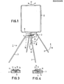
- the embodiment of a stand shown in Figures 1 to 4 has a base frame 1, which is composed of four legs 2 and a central base part 3.
- a frame-like holder 4, which serves to accommodate advertising media, such as posters, signs or the like, is pivotally mounted on the base frame 1.
- This support shaft 6 is connected to the holder 4, in the example shown in FIGS. 1 to 4 via a pendulum rod 7 which is fastened to the holder 4 and carries a pendulum weight 8 at its free end.
- the pendulum weight 8 causes the holder 4 to return to the rest position, which is shown in FIG. 3.
- the pendulum weight 8 is preferably formed by a vessel into which a weighting material such as water or sand can be filled.
- the pendulum 8 can be removably attached to the P endelstange be attached. 7
- the pendulum rod 7 is on the lower bar 9 of the frame-like bracket 4 attached.
- the support shaft 6 has flattened portions 10 on its upper side, and plates designed as leaf springs 11 are attached to the base frame middle part 3 and extend transversely to the longitudinal extension of the support shaft 6 just above the flattened portions 10. These leaf springs 11 are adjustable with screws 12. When the holder 4 or the support shaft 6 is deflected, the support shaft first rotates freely and then the leaf springs 11 come into contact with the edges 14 of the flats 10 (as shown in FIG. 4) and this results in a rapid return of the holder to the rest position ( Fig. 3) and damping of the pendulum movement brought about as soon as the wind force deflecting the holder stops; the leaf springs stabilize the stay of the holder 4 in its rest position.
- a pair of the legs 2 is formed by the two legs of a U-bracket 15.
- the U-brackets 15 are pivotally mounted in their center on the center frame part 3; the geometric pivot axes of the two U-brackets run transversely to the pivot axis of the support shaft 6, which supports the bracket 4 in an oscillating manner.
- the bracket 4 is approximately parallel position in a reference to the pivot axes of the U-bracket; in this position, the U-bracket can be placed flat on the bracket 4, and these parts form a flat package.
- the height of this package can be further reduced if the pendulum rod 7 in the holder 4 can be inserted;
- the support shaft 6 can be inserted into the recess 20, which is provided in the middle part 3 of the base, or can be passed through this recess; this results in a favorable positioning of the holder 4 with respect to the center frame part 3 during storage and transport.
- the intended position of the pendulum mounting of the holder 4 gives the possibility of presenting displays, posters or the like of different sizes without requiring a change to the base frame.
- the holder is pivotally mounted with pins 21 which engage in recesses 22 which are provided on the center frame part 3 of the base.
- This type of storage is low-friction.
- a recess 20 is provided in the middle part 3 of the base frame; the pins 21 attached to the lower bar 9 of the holder engage in them when the holder is rotated by 90 ° when the stand is folded.
- the legs 2 are screwed or plugged onto the foot frame middle tail 3.
- There are 3 pins 25 arranged on the base frame part; onto which the legs 2 can be screwed or attached. Instead of these pins, one can also provide 3 bores in the middle part of the base frame, which are appropriately dimensioned to insert the ends of the legs 2 or which carry a thread which corresponds to a thread provided at the end of the legs.
- a rigid plate 30 is arranged above the flattened portion 10 of the supporting shaft or a bearing journal.
- the plate 30 is held on the bearing body 32 with two screw bolts 31 and is pressed against the bearing body with coil springs 33.
- the coil springs 33 can be compressed in order to hold the plate in contact under adjustable preload on the bearing body and upon deflection of the supporting shaft or the bearing journal at the edges 14 of the flattening.
- a ring 35 which has a straight section 36, is placed over the section of the supporting shaft or a bearing journal which has the flat 10; the section 36 of the ring 35 forms a rod which rests on the flat 10.
- the ring 35 is pulled down by a spring 37.
- the effective force of the spring 37 which determines the pressure of the rod against the flattened portion, is adjustable with a screw nut 38, which is screwed onto a bolt attached to the ring 35 and extending through the spring 37.
- the spring 37 is supported on the bearing body 32.
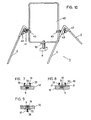
- the fender bearing has two bearing journals 41 which are mounted in alignment with one another on a rekan carrier 40 and which engage in bearing recesses 42 which are provided in bearing bodies 43 of the base frame.
- the advertising medium 40 is shown as a frame, but can also be in another form, e.g. as a physical replica of the objects to be advertised.
- the bearing pins 41 are arranged on terminals 45, which in turn engage the advertising carrier 40.
- a threaded section 46 which projects beyond the bearing recess 42 in question and onto which a nut 47 designed as a handle can be screwed, which presses a brake disc 49 against the bearing body 43 via a spring 48; the braking or damping of the pendulum movement can be adjusted by adjusting the nut 47.
- flats 10 are provided on the bearing pins 41 to reduce the amplitude of the pendulum movement and to damp them, and the bearing bodies 43 in the area of the flats 10 are open at the top. Above the flattened areas 10, resilient plates 30 are arranged, which, analogously as shown in FIGS.
- the pendulum weight 8 is arranged in this embodiment on a clamp 50 which engages the advertising carrier 40.
- the pendulum weight can be formed by a vessel into which weighting material can be filled as required.
- the base frame consists of two bearing bodies 43 and of legs 2 which can be screw-connected or plug-connected thereto.
- the embodiment according to FIG. 12 differs from the embodiment according to FIGS. 10 and 11 in the design of the brine by two U-brackets 52, each of one to the other bearing body and the leg ends 53 are connected to the bearing bodies 43. This training has good stability.
- the embodiment according to FIG. 13 has a base frame which consists of a U-bracket 54 and two elongated feet 55. The feet are arranged on the middle part 56 of the U-bracket.
- the bearing body 43 of the self-aligning bearing configured analogously to the embodiment according to FIGS. 10 and 11 are attached to the leg ends 57 of the U-bracket 54.
Landscapes
- Physics & Mathematics (AREA)
- General Physics & Mathematics (AREA)
- Engineering & Computer Science (AREA)
- Theoretical Computer Science (AREA)
- Medicines Containing Plant Substances (AREA)
- Pivots And Pivotal Connections (AREA)
- Cosmetics (AREA)
- Steroid Compounds (AREA)
- Vibration Prevention Devices (AREA)
- Tables And Desks Characterized By Structural Shape (AREA)
- Catching Or Destruction (AREA)
Priority Applications (1)
| Application Number | Priority Date | Filing Date | Title |
|---|---|---|---|
| AT87890085T ATE66760T1 (de) | 1986-04-25 | 1987-04-24 | Aufsteller zur beweglichen anbringung von reklametraegern. |
Applications Claiming Priority (2)
| Application Number | Priority Date | Filing Date | Title |
|---|---|---|---|
| DE8611481U | 1986-04-25 | ||
| DE8611481U DE8611481U1 (de) | 1986-04-25 | 1986-04-25 | Aufsteller zur beweglichen Anbringung von Reklameträgern |
Publications (2)
| Publication Number | Publication Date |
|---|---|
| EP0243345A1 true EP0243345A1 (fr) | 1987-10-28 |
| EP0243345B1 EP0243345B1 (fr) | 1991-08-28 |
Family
ID=6794092
Family Applications (1)
| Application Number | Title | Priority Date | Filing Date |
|---|---|---|---|
| EP87890085A Expired - Lifetime EP0243345B1 (fr) | 1986-04-25 | 1987-04-24 | Support pour l'affichage mobile des représentations publicitaires |
Country Status (6)
| Country | Link |
|---|---|
| US (1) | US4957258A (fr) |
| EP (1) | EP0243345B1 (fr) |
| AT (1) | ATE66760T1 (fr) |
| DE (2) | DE8611481U1 (fr) |
| DK (1) | DK164248C (fr) |
| NO (1) | NO172666C (fr) |
Cited By (5)
| Publication number | Priority date | Publication date | Assignee | Title |
|---|---|---|---|---|
| GB2203642A (en) * | 1987-04-21 | 1988-10-26 | Rsj Displays Limited | Display unit |
| EP0348723A1 (fr) * | 1988-06-25 | 1990-01-03 | Venture Projects (UK) Limited | Enseigne rotative |
| FR2662289A1 (fr) * | 1990-05-16 | 1991-11-22 | Feuvray Beatrice | Dispositif de signalisation a la fois portatif et antivent. |
| GB2248960A (en) * | 1990-10-20 | 1992-04-22 | Peter Andre Drapans | Improvements in and relating to display signs |
| FR2678414A1 (fr) * | 1991-06-28 | 1992-12-31 | Jusot Lionel | Dispositif a panneau pivotant pour presenter une information. |
Families Citing this family (11)
| Publication number | Priority date | Publication date | Assignee | Title |
|---|---|---|---|---|
| US5377433A (en) * | 1992-07-07 | 1995-01-03 | Hazlehurst; Laurance N. | Dynamic artwork display |
| USD353912S (en) | 1993-05-05 | 1994-12-27 | Hsuan-Sen Shiao | Adjustable lamp stand base |
| US5357895A (en) * | 1993-06-16 | 1994-10-25 | Cekcom Corporation | Illuminated marine advertising vessel |
| US5377945A (en) * | 1993-12-13 | 1995-01-03 | Steinke; Michael E. | Mount for redressably mounting a sign |
| GR1003355B (el) * | 1999-05-13 | 2000-04-05 | Πλωτος πινακας αγγελιων | |
| CN100587765C (zh) * | 2003-10-13 | 2010-02-03 | 科茨塞克有限公司 | 多显示面的显示设备 |
| WO2005036506A1 (fr) * | 2003-10-13 | 2005-04-21 | Coates Signco Pty Limited | Dispositif d'affichage a faces multiples |
| AU2004280650B2 (en) * | 2003-10-13 | 2009-10-01 | Coates Signco Pty Limited | Multiple sided display device |
| IES86693B2 (en) * | 2014-09-19 | 2016-08-10 | O'donovan Damien | A freestanding self-righting frame |
| US10152903B2 (en) * | 2014-10-23 | 2018-12-11 | SignsDirect Inc. | Swinging sign apparatus |
| WO2020039265A1 (fr) * | 2019-01-07 | 2020-02-27 | Najafian Asad | Panneau d'affichage dynamique |
Citations (6)
| Publication number | Priority date | Publication date | Assignee | Title |
|---|---|---|---|---|
| DE627993C (de) * | 1936-03-27 | Kaufmann Metallwerk J C F | An Angeln vetschwenkbarer und in deren Achse verschiebbarer Reklameeinsteckschilderramen | |
| US2467187A (en) * | 1945-06-16 | 1949-04-12 | Lyle C Capper | Weighted pivoted sign |
| GB834418A (en) * | 1956-05-03 | 1960-05-11 | I R S Ltd | Improvements in or relating to temporary signs, notices and like indicators |
| GB1428971A (en) * | 1972-05-22 | 1976-03-24 | Graphic Trend Ass Ltd | Display device |
| DE8523986U1 (de) * | 1985-08-21 | 1985-10-24 | Tiedemann, Roman, Wien | Einrichtung zur Anbringung von Ankündigungstafeln |
| US4553346A (en) * | 1983-07-05 | 1985-11-19 | Dynagraphic Merchandising Corp. | Display device |
Family Cites Families (19)
| Publication number | Priority date | Publication date | Assignee | Title |
|---|---|---|---|---|
| US242944A (en) * | 1881-06-14 | peters | ||
| US760890A (en) * | 1903-12-08 | 1904-05-24 | George T Mackinder | Hinge. |
| US1781161A (en) * | 1926-04-16 | 1930-11-11 | Carrey Morse Engineering Compa | Adjustable mounting |
| US1856349A (en) * | 1932-01-11 | 1932-05-03 | Bigelow Joseph Prescott | Sign |
| US2059582A (en) * | 1934-01-24 | 1936-11-03 | Hurewitz Alexander | Finding for a clasp |
| US2084818A (en) * | 1937-03-20 | 1937-06-22 | Joc R Neil | Billboard |
| GB531985A (en) * | 1939-08-10 | 1941-01-15 | Percy Shaw | Improvements relating to signs for roadways |
| US2584404A (en) * | 1947-07-14 | 1952-02-05 | Iron Fireman Mfg Co | Furnace door structure with spring and cam retention means |
| US2607590A (en) * | 1949-10-28 | 1952-08-19 | Henry H Wheaton | Rocking support |
| US2907992A (en) * | 1957-04-29 | 1959-10-06 | Mc Graw Edison Co | Mounting means for temperature indicating device |
| US3521390A (en) * | 1967-12-07 | 1970-07-21 | Thomas W Carlson | Signboard wind load limiting apparatus |
| US3524615A (en) * | 1968-05-02 | 1970-08-18 | Albert W Beasley | Refuse container support |
| US3687092A (en) * | 1970-10-12 | 1972-08-29 | Republic Molding Corp | Molded furniture |
| US3880280A (en) * | 1973-07-11 | 1975-04-29 | David B Fyvolent | Display device for garment racks |
| CH618532A5 (fr) * | 1977-11-22 | 1980-07-31 | Alain Feuvray | |
| US4258952A (en) * | 1978-12-15 | 1981-03-31 | Dutra Antonio S | Rocking couch, chaise, lounge, recliner, chair or relaxer |
| US4365435A (en) * | 1980-11-03 | 1982-12-28 | Chicago Display Company | Portable sign |
| SE437195B (sv) * | 1983-11-17 | 1985-02-11 | Bernt Holm | Anordning vid skyltstellningar och liknande |
| US4599988A (en) * | 1985-08-15 | 1986-07-15 | Walter Madurski | Portable barbecue |
-
1986
- 1986-04-25 DE DE8611481U patent/DE8611481U1/de not_active Expired
-
1987
- 1987-04-24 DE DE8787890085T patent/DE3772431D1/de not_active Expired - Lifetime
- 1987-04-24 AT AT87890085T patent/ATE66760T1/de not_active IP Right Cessation
- 1987-04-24 US US07/042,062 patent/US4957258A/en not_active Expired - Lifetime
- 1987-04-24 EP EP87890085A patent/EP0243345B1/fr not_active Expired - Lifetime
- 1987-04-24 NO NO871714A patent/NO172666C/no not_active IP Right Cessation
- 1987-04-24 DK DK210887A patent/DK164248C/da not_active IP Right Cessation
Patent Citations (6)
| Publication number | Priority date | Publication date | Assignee | Title |
|---|---|---|---|---|
| DE627993C (de) * | 1936-03-27 | Kaufmann Metallwerk J C F | An Angeln vetschwenkbarer und in deren Achse verschiebbarer Reklameeinsteckschilderramen | |
| US2467187A (en) * | 1945-06-16 | 1949-04-12 | Lyle C Capper | Weighted pivoted sign |
| GB834418A (en) * | 1956-05-03 | 1960-05-11 | I R S Ltd | Improvements in or relating to temporary signs, notices and like indicators |
| GB1428971A (en) * | 1972-05-22 | 1976-03-24 | Graphic Trend Ass Ltd | Display device |
| US4553346A (en) * | 1983-07-05 | 1985-11-19 | Dynagraphic Merchandising Corp. | Display device |
| DE8523986U1 (de) * | 1985-08-21 | 1985-10-24 | Tiedemann, Roman, Wien | Einrichtung zur Anbringung von Ankündigungstafeln |
Cited By (9)
| Publication number | Priority date | Publication date | Assignee | Title |
|---|---|---|---|---|
| GB2203642A (en) * | 1987-04-21 | 1988-10-26 | Rsj Displays Limited | Display unit |
| GB2203642B (en) * | 1987-04-21 | 1991-02-13 | Rsj Displays Limited | Display unit |
| EP0348723A1 (fr) * | 1988-06-25 | 1990-01-03 | Venture Projects (UK) Limited | Enseigne rotative |
| FR2662289A1 (fr) * | 1990-05-16 | 1991-11-22 | Feuvray Beatrice | Dispositif de signalisation a la fois portatif et antivent. |
| WO1991018380A1 (fr) * | 1990-05-16 | 1991-11-28 | Feuvray Beatrice | Dispositif de signalisation a la fois portatif et antivent |
| US5329875A (en) * | 1990-05-16 | 1994-07-19 | Beatrice Feuvray | Portable and wind-resistant signalling device |
| GB2248960A (en) * | 1990-10-20 | 1992-04-22 | Peter Andre Drapans | Improvements in and relating to display signs |
| GB2248960B (en) * | 1990-10-20 | 1994-11-02 | Peter Andre Drapans | Improvements in and relating to display signs |
| FR2678414A1 (fr) * | 1991-06-28 | 1992-12-31 | Jusot Lionel | Dispositif a panneau pivotant pour presenter une information. |
Also Published As
| Publication number | Publication date |
|---|---|
| NO172666B (no) | 1993-05-10 |
| ATE66760T1 (de) | 1991-09-15 |
| DK210887D0 (da) | 1987-04-24 |
| NO871714D0 (no) | 1987-04-24 |
| DE8611481U1 (de) | 1986-06-05 |
| NO172666C (no) | 1993-08-18 |
| US4957258A (en) | 1990-09-18 |
| DE3772431D1 (de) | 1991-10-02 |
| DK210887A (da) | 1987-10-26 |
| DK164248C (da) | 1992-11-02 |
| EP0243345B1 (fr) | 1991-08-28 |
| DK164248B (da) | 1992-05-25 |
| NO871714L (no) | 1987-10-26 |
Similar Documents
| Publication | Publication Date | Title |
|---|---|---|
| EP0243345B1 (fr) | Support pour l'affichage mobile des représentations publicitaires | |
| DE3509224A1 (de) | Zeichenstaender mit flexibler tafel | |
| DE19703157A1 (de) | Verbesserter Lastenträger | |
| DE535239C (de) | Vorrichtung zur Schaustellung von Plakaten, Ankuendigungstafeln, insbesondere aus duennen Werkstoffen | |
| DE1258541C2 (de) | Rost fuer grossfeuerungsanlagen | |
| DE3815196C2 (de) | Schwenktafel | |
| DE3420608C2 (de) | Vorrichtung zur Halterung und Präsentation von in SB-Verpackungen befindlichen Waren | |
| DE1918236C3 (fr) | ||
| DE8706502U1 (de) | Tafel mit auswechselbarem Untergrund zur vielfältigen Verwendung | |
| DE19621089A1 (de) | Halterung für eine CD-Hülle | |
| DE212019000270U1 (de) | Vorrichtung zum Ausgeben und Expandieren eines expandierbaren geschlitzten Bogenmaterials | |
| DE69100259T2 (de) | Plattenwärmetauscher. | |
| DE6947579U (de) | Vorrichtung, insbesondere saeule fuer reklamezwecke. | |
| AT405698B (de) | Präsentationsvorrichtung für ein plakat | |
| EP0612491A2 (fr) | Stand d'exposition pour des carreaux | |
| DE817274C (de) | Vorratsbehaelter fuer einen Stapel von Gegenstaenden | |
| DE3033973C2 (de) | Aus Faltmaterial hergestellter Bodenaufsteller für Waren in einem Ladengeschäft | |
| DE958813C (de) | Bleistiftspitzmaschine | |
| DE1812612C3 (de) | Ständer für Reklame und sonstige Anzeigezwecke | |
| DE8914745U1 (de) | Schienenartiger Werbeträger | |
| DE1812612B2 (de) | Staender fuer reklame und sonstige anzeigezwecke | |
| DE8129246U1 (de) | "halterungsvorrichtung fuer gitarren od.dgl." | |
| DE2832918A1 (de) | Trainingsgeraet fuer sport- und rehabilitationszwecke | |
| DE1873518U (de) | Fuellhalterstaender. | |
| DE1055347B (de) | Zusammensetzbarer Halter zur Schaustellung von Gegenstaenden |
Legal Events
| Date | Code | Title | Description |
|---|---|---|---|
| PUAI | Public reference made under article 153(3) epc to a published international application that has entered the european phase |
Free format text: ORIGINAL CODE: 0009012 |
|
| AK | Designated contracting states |
Kind code of ref document: A1 Designated state(s): AT BE CH DE FR GB IT LI NL SE |
|
| 17P | Request for examination filed |
Effective date: 19871109 |
|
| 17Q | First examination report despatched |
Effective date: 19891129 |
|
| GRAA | (expected) grant |
Free format text: ORIGINAL CODE: 0009210 |
|
| ITF | It: translation for a ep patent filed | ||
| AK | Designated contracting states |
Kind code of ref document: B1 Designated state(s): AT BE CH DE FR GB IT LI NL SE |
|
| PG25 | Lapsed in a contracting state [announced via postgrant information from national office to epo] |
Ref country code: BE Effective date: 19910828 |
|
| REF | Corresponds to: |
Ref document number: 66760 Country of ref document: AT Date of ref document: 19910915 Kind code of ref document: T |
|
| GBT | Gb: translation of ep patent filed (gb section 77(6)(a)/1977) | ||
| REF | Corresponds to: |
Ref document number: 3772431 Country of ref document: DE Date of ref document: 19911002 |
|
| ET | Fr: translation filed | ||
| PG25 | Lapsed in a contracting state [announced via postgrant information from national office to epo] |
Ref country code: LI Effective date: 19920430 Ref country code: CH Effective date: 19920430 |
|
| PLBE | No opposition filed within time limit |
Free format text: ORIGINAL CODE: 0009261 |
|
| STAA | Information on the status of an ep patent application or granted ep patent |
Free format text: STATUS: NO OPPOSITION FILED WITHIN TIME LIMIT |
|
| 26N | No opposition filed | ||
| REG | Reference to a national code |
Ref country code: CH Ref legal event code: AUV Free format text: DAS OBENGENANNTE PATENT IST, MANGELS BEZAHLUNG DER 6. JAHRESGEBUEHR GELOESCHT WORDEN. Ref country code: CH Ref legal event code: PL |
|
| EAL | Se: european patent in force in sweden |
Ref document number: 87890085.1 |
|
| REG | Reference to a national code |
Ref country code: GB Ref legal event code: IF02 |
|
| PGFP | Annual fee paid to national office [announced via postgrant information from national office to epo] |
Ref country code: SE Payment date: 20030404 Year of fee payment: 17 |
|
| PGFP | Annual fee paid to national office [announced via postgrant information from national office to epo] |
Ref country code: FR Payment date: 20030408 Year of fee payment: 17 |
|
| PGFP | Annual fee paid to national office [announced via postgrant information from national office to epo] |
Ref country code: AT Payment date: 20030411 Year of fee payment: 17 |
|
| PGFP | Annual fee paid to national office [announced via postgrant information from national office to epo] |
Ref country code: GB Payment date: 20030423 Year of fee payment: 17 |
|
| PGFP | Annual fee paid to national office [announced via postgrant information from national office to epo] |
Ref country code: NL Payment date: 20030429 Year of fee payment: 17 |
|
| PGFP | Annual fee paid to national office [announced via postgrant information from national office to epo] |
Ref country code: DE Payment date: 20030502 Year of fee payment: 17 |
|
| PG25 | Lapsed in a contracting state [announced via postgrant information from national office to epo] |
Ref country code: GB Free format text: LAPSE BECAUSE OF NON-PAYMENT OF DUE FEES Effective date: 20040424 Ref country code: AT Free format text: LAPSE BECAUSE OF NON-PAYMENT OF DUE FEES Effective date: 20040424 |
|
| PG25 | Lapsed in a contracting state [announced via postgrant information from national office to epo] |
Ref country code: SE Free format text: LAPSE BECAUSE OF NON-PAYMENT OF DUE FEES Effective date: 20040425 |
|
| PG25 | Lapsed in a contracting state [announced via postgrant information from national office to epo] |
Ref country code: NL Free format text: LAPSE BECAUSE OF NON-PAYMENT OF DUE FEES Effective date: 20041101 |
|
| PG25 | Lapsed in a contracting state [announced via postgrant information from national office to epo] |
Ref country code: DE Free format text: LAPSE BECAUSE OF NON-PAYMENT OF DUE FEES Effective date: 20041103 |
|
| EUG | Se: european patent has lapsed | ||
| GBPC | Gb: european patent ceased through non-payment of renewal fee |
Effective date: 20040424 |
|
| PG25 | Lapsed in a contracting state [announced via postgrant information from national office to epo] |
Ref country code: FR Free format text: LAPSE BECAUSE OF NON-PAYMENT OF DUE FEES Effective date: 20041231 |
|
| NLV4 | Nl: lapsed or anulled due to non-payment of the annual fee |
Effective date: 20041101 |
|
| REG | Reference to a national code |
Ref country code: FR Ref legal event code: ST |
|
| PG25 | Lapsed in a contracting state [announced via postgrant information from national office to epo] |
Ref country code: IT Free format text: LAPSE BECAUSE OF NON-PAYMENT OF DUE FEES;WARNING: LAPSES OF ITALIAN PATENTS WITH EFFECTIVE DATE BEFORE 2007 MAY HAVE OCCURRED AT ANY TIME BEFORE 2007. THE CORRECT EFFECTIVE DATE MAY BE DIFFERENT FROM THE ONE RECORDED. Effective date: 20050424 |