EP0243637A2 - Module de puissance à semi-conducteur - Google Patents
Module de puissance à semi-conducteur Download PDFInfo
- Publication number
- EP0243637A2 EP0243637A2 EP87103618A EP87103618A EP0243637A2 EP 0243637 A2 EP0243637 A2 EP 0243637A2 EP 87103618 A EP87103618 A EP 87103618A EP 87103618 A EP87103618 A EP 87103618A EP 0243637 A2 EP0243637 A2 EP 0243637A2
- Authority
- EP
- European Patent Office
- Prior art keywords
- ceramic substrate
- housing
- power semiconductor
- substrate
- semiconductor module
- Prior art date
- Legal status (The legal status is an assumption and is not a legal conclusion. Google has not performed a legal analysis and makes no representation as to the accuracy of the status listed.)
- Granted
Links
Images

Classifications
-
- H—ELECTRICITY
- H10—SEMICONDUCTOR DEVICES; ELECTRIC SOLID-STATE DEVICES NOT OTHERWISE PROVIDED FOR
- H10W—GENERIC PACKAGES, INTERCONNECTIONS, CONNECTORS OR OTHER CONSTRUCTIONAL DETAILS OF DEVICES COVERED BY CLASS H10
- H10W76/00—Containers; Fillings or auxiliary members therefor; Seals
- H10W76/10—Containers or parts thereof
- H10W76/12—Containers or parts thereof characterised by their shape
- H10W76/13—Containers comprising a conductive base serving as an interconnection
- H10W76/136—Containers comprising a conductive base serving as an interconnection having other interconnections perpendicular to the conductive base
-
- H—ELECTRICITY
- H10—SEMICONDUCTOR DEVICES; ELECTRIC SOLID-STATE DEVICES NOT OTHERWISE PROVIDED FOR
- H10W—GENERIC PACKAGES, INTERCONNECTIONS, CONNECTORS OR OTHER CONSTRUCTIONAL DETAILS OF DEVICES COVERED BY CLASS H10
- H10W90/00—Package configurations
Definitions
- the invention relates to a power semiconductor module with a module housing and a ceramic substrate used as the housing base according to the preamble of claim 1 and claim 5.
- a power semiconductor module with a module housing and a ceramic substrate used as the housing base according to the preamble of claim 1 and claim 5.
- modules are usually brought into contact with a heat sink, for which a screw connection is generally provided .
- Power semiconductor modules with screw mounting are known in different designs e.g. with mounting flanges formed on the outside of the housing or, in the case of frame-shaped housings, also with a central fastening part which has at least one bore for a fastening screw.
- the invention is therefore based on the object of specifying further measures for reducing the risk of breakage for power semiconductors with a plastic housing and a base made of a ceramic substrate.
- the preamble of claim 1 relates to the module known from DE-OS 30 28 178, the preamble of claim 5 to the module known from DE-OS 31 27 457.
- the metallization surfaces provided for mechanical reinforcement can be produced easily and simultaneously with the other metallization surfaces for electrical lines.
- the solution can be used for different module designs.
- the ceramic substrate can press on a heat sink with high and even contact pressure and is effectively protected against cracking.
- the embodiment relates to a power semiconductor module, which is known from DE-OS 30 28 178.
- the power semiconductor module has an approximately cuboid plastic housing with a central fastening part and has a ceramic substrate as the bottom.
- the module represents an implementation of an uncontrolled single-phase rectifier circuit (Graetz bridge).
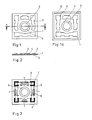
- Fig. 1 shows a plan view of the module interior facing top of a ceramic substrate 1, which can be inserted into a housing of the module known from DE-OS 30 28 178.
- the substrate 1 is preferably made of 96% Al2O3 and has an opening 2 in the middle for carrying out a fastening screw.
- Conductor tracks 3 and a reinforcing ring 4 according to the invention are arranged on the top of the substrate 1 and in the region of the opening 2.
- the width of the reinforcement ring 4 is, for example, 2 mm and corresponds approximately to a support surface 18 in a recess 17 of a central fastening part 13 of a housing 12, which is shown in FIG. 4.
- the distance of the reinforcement ring 4 to the inner metallization pattern, that is to say to the conductor tracks 3, is dimensioned such that the insulation resistance of the inner circuit to the outside to a heat sink is ensured after the module has been cast with casting compound.
- the distance between the reinforcing ring 4 and a copper layer 5 (see FIG. 2) on the underside of the ceramic substrate that is to say the distance between the thickness of the ceramic substrate Reinforcement ring 4 and copper layer 5 at the edge of the opening 2 generally cannot act as an insulation section, since the ceramic is not covered with potting compound at this point. Also between the outer edge of the ceramic substrate 1, on which an outer frame 14 of the housing 12 (see FIG. 6) is supported, and the conductor tracks 3, an insulation edge must be observed.
- the minimum distances to be maintained between metallization surfaces depend on the blocking voltages to be observed, on the insulation strength of the casting compound and finally on the resolution of the masking and etching technology used (e.g. screen printing process).
- the conductor tracks 3 and the reinforcement ring 4 on the upper side of the ceramic substrate 1 by direct connection (direct bonding method) of a 0.1 to 0.5 mm, preferably 0.3 mm thick copper foil to the ceramic substrate 1 This is done by using a film covering the entire surface of the top of the substrate 1, which is then etched.
- a copper foil is expediently used, which is approximately the same thickness as the foil used for the top-side metallization and into which a hole corresponding to the opening 2 has already been punched. The underside of the substrate 1 then no longer needs to be etched.
- the copper surfaces of the substrate metallized in this way are then appropriately chemically nickel-plated and prepared for the subsequent soldering process.
- FIG. 2 shows a section through the section plane AA of the substrate 1 entered in FIG. 1. From this it can be seen that on the underside of the ceramic substrate 1 a copper layer 5 is provided, which has approximately the same thickness as the reinforcing ring 4 and is also expediently connected directly to the substrate 1.
- the reinforcement ring 4 and the copper layer 5 have no electrical function. They serve only for mechanical reinforcement of the substrate 1 and, in their combination, bring about a significant reduction in the risk of breakage in comparison with the known substrate design.
- the invention can be applied in a corresponding manner for larger modules that are fastened with several screws.
- an outer reinforcement ring 6 can be provided on the ceramic substrate 1, which is designed and manufactured in the region of the opening 2 in the same way as the reinforcement ring 4. It may be necessary to increase the area of the ceramic substrate 1 somewhat, since certain distances between the conductor tracks 3 and the outer reinforcement ring 6 or the reinforcement ring 4 in the region of the opening 2 must be maintained with regard to the necessary insulation distances.
- the housing 12 in the region of its second bearing surface 18.1 in the second recess 17.1 of the frame 14 must be adapted accordingly (cf. FIG. 4 and the associated description).
- an outer reinforcement ring can also be provided on the substrate to protect a ceramic substrate inserted into the base surface.
- an outer reinforcement ring could advantageously be provided in a module according to DE-OS 31 27 457.
- FIG. 3 shows the upper side of the substrate 1 shown in FIGS. 1 and 2 after it has been soldered to placement elements.
- four diode chips 7, four copper clips 8 are soldered onto the ceramic substrate 1 as module-internal connecting elements between the anodes of the chips 7 and the conductor tracks 3 and four tabs 9 as external connections with a soft solder with a melting point around 300 ° C. without flux .
- the provided glass passivated diode chips 7 are soldered with the anodes upwards onto the substrate 1, so that the passivation area of the diodes 7 is at the top.
- planar passivated diode chips could also be used instead.
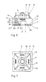
- FIG. 5 shows the individual parts that are required for producing the fully assembled substrate 1 shown in FIG. 3. From this it can be seen that the tabs 9 have an expansion curve 10 at their base and that the soft solder is advantageously applied as a solder foil 11.
- the housing 12 has an outer frame 14 and a central fastening part 13, which is rigid with the frame 14 via ribs 15 connected is. It consists of a glass fiber reinforced plastic, which offers enough resistance to the pressure of a fastening screw even when heated to ensure fastening during many years of operation.
- the ribs 15 and the central fastening part 13 are designed so that they also act as extension paths to maintain the required creepage distances and clearances.
- the central fastening part 13 is therefore made relatively high, with a recess 16 for receiving the screw head.
- the central fastening part 13 has a recess 17 on its underside with a bearing surface 18 for the metallized substrate 1.
- the outer frame 14 of the housing 12 also has a second recess 17.1 on its underside with a second contact surface 18.1. In the second recess 17.1, a groove 19 is also provided for receiving excess adhesive.
- FIG. 6 shows a side view of the finished module after the assembled substrate 1 is glued into the housing 12 with an elastic, electrically insulating adhesive.
- the gluing point is both the contact surface 18 on the central fastening part 13 and the second contact surface 18.1 on the outer frame 14 of the housing 12.
- the elastic adhesive relieves the substrate 1 from the housing 12.
- the module is covered with a soft elastomeric casting compound 20 (preferably a silicone -Elastomer) of high purity, which protects the sensitive chips 7 (not visible in FIG. 6) and the soldered connections of the clips 8 from mechanical stresses.
- the above-mentioned high purity of the potting compound 20 is necessary in order to keep harmful ions away from the chips 7 and to ensure the insulation strength.
- the casting height is set so that completely immerse the expansion elbows 10 of the tabs 9 in the sealing compound 20.
- the module is filled with a thermosetting hard casting compound 21, preferably an epoxy resin, up to a fill level 22 below the upper edge of the outer frame 14 for sealing upwards.
- the tabs 9 are fixed in their position.
Landscapes
- Cooling Or The Like Of Semiconductors Or Solid State Devices (AREA)
- Control Of Motors That Do Not Use Commutators (AREA)
Priority Applications (1)
| Application Number | Priority Date | Filing Date | Title |
|---|---|---|---|
| AT87103618T ATE84378T1 (de) | 1986-03-26 | 1987-03-12 | Leistungshalbleitermodul. |
Applications Claiming Priority (2)
| Application Number | Priority Date | Filing Date | Title |
|---|---|---|---|
| DE3610288 | 1986-03-26 | ||
| DE19863610288 DE3610288A1 (de) | 1986-03-26 | 1986-03-26 | Leistungshalbleitermodul |
Publications (3)
| Publication Number | Publication Date |
|---|---|
| EP0243637A2 true EP0243637A2 (fr) | 1987-11-04 |
| EP0243637A3 EP0243637A3 (en) | 1990-05-16 |
| EP0243637B1 EP0243637B1 (fr) | 1993-01-07 |
Family
ID=6297367
Family Applications (1)
| Application Number | Title | Priority Date | Filing Date |
|---|---|---|---|
| EP87103618A Expired - Lifetime EP0243637B1 (fr) | 1986-03-26 | 1987-03-12 | Module de puissance à semi-conducteur |
Country Status (3)
| Country | Link |
|---|---|
| EP (1) | EP0243637B1 (fr) |
| AT (1) | ATE84378T1 (fr) |
| DE (2) | DE3610288A1 (fr) |
Cited By (3)
| Publication number | Priority date | Publication date | Assignee | Title |
|---|---|---|---|---|
| EP0391832A3 (fr) * | 1989-04-05 | 1991-06-05 | Fagor, S.Coop. Ltda. | Amélioration dans la construction de redresseurs en pont |
| GB2241110A (en) * | 1990-02-19 | 1991-08-21 | Mitsubishi Electric Corp | Semiconductor package |
| EP0505193A1 (fr) * | 1991-03-21 | 1992-09-23 | Harris Corporation | Couvercle pour empaquetage de composants électriques |
Families Citing this family (8)
| Publication number | Priority date | Publication date | Assignee | Title |
|---|---|---|---|---|
| DE3837920A1 (de) * | 1988-11-09 | 1990-05-10 | Semikron Elektronik Gmbh | Halbleiterelement |
| JPH05166969A (ja) * | 1991-10-14 | 1993-07-02 | Fuji Electric Co Ltd | 半導体装置 |
| DE4300516C2 (de) * | 1993-01-12 | 2001-05-17 | Ixys Semiconductor Gmbh | Leistungshalbleitermodul |
| EP0671766A1 (fr) * | 1994-02-25 | 1995-09-13 | Harris Corporation | Boîtier semi-conducteur et son procédé de fabrication |
| DE4407810C2 (de) * | 1994-03-09 | 1998-02-26 | Semikron Elektronik Gmbh | Schaltungsanordnung (Modul) |
| DE102004035746B4 (de) * | 2004-07-23 | 2009-04-16 | Infineon Technologies Ag | Leistungshalbleitermodul |
| DE102006005445A1 (de) * | 2006-02-07 | 2007-08-16 | Semikron Elektronik Gmbh & Co. Kg | Leistungshalbleitermodul |
| CN102013578B (zh) * | 2009-09-07 | 2014-05-28 | 比亚迪股份有限公司 | 导体引出结构以及功率模块 |
Family Cites Families (8)
| Publication number | Priority date | Publication date | Assignee | Title |
|---|---|---|---|---|
| DE1861572U (de) * | 1962-08-17 | 1962-11-08 | Steatit Magnesia Ag | Scheibenfoermiges bauelement fuer nachrichtentechnische oder aehnliche geraete. |
| DE3028178C2 (de) * | 1980-07-25 | 1985-05-09 | Brown, Boveri & Cie Ag, 6800 Mannheim | Leistungshalbleiter-Modul |
| US4367523A (en) * | 1981-02-17 | 1983-01-04 | Electronic Devices, Inc. | Rectifier bridge unit |
| DE3127457C2 (de) * | 1981-07-11 | 1985-09-12 | Brown, Boveri & Cie Ag, 6800 Mannheim | Stromrichtermodul |
| DE3241509A1 (de) * | 1982-11-10 | 1984-05-10 | Brown, Boveri & Cie Ag, 6800 Mannheim | Leistungstransistor-modul |
| DE3241508A1 (de) * | 1982-11-10 | 1984-05-10 | Brown, Boveri & Cie Ag, 6800 Mannheim | Leistungstransistor-modul |
| DE3307704C2 (de) * | 1983-03-04 | 1986-10-23 | Brown, Boveri & Cie Ag, 6800 Mannheim | Stromrichtermodul mit Befestigungslaschen |
| DE3323246A1 (de) * | 1983-06-28 | 1985-01-10 | Brown, Boveri & Cie Ag, 6800 Mannheim | Leistungshalbleitermodul |
-
1986
- 1986-03-26 DE DE19863610288 patent/DE3610288A1/de not_active Withdrawn
-
1987
- 1987-03-12 EP EP87103618A patent/EP0243637B1/fr not_active Expired - Lifetime
- 1987-03-12 AT AT87103618T patent/ATE84378T1/de active
- 1987-03-12 DE DE8787103618T patent/DE3783385D1/de not_active Expired - Lifetime
Cited By (5)
| Publication number | Priority date | Publication date | Assignee | Title |
|---|---|---|---|---|
| EP0391832A3 (fr) * | 1989-04-05 | 1991-06-05 | Fagor, S.Coop. Ltda. | Amélioration dans la construction de redresseurs en pont |
| GB2241110A (en) * | 1990-02-19 | 1991-08-21 | Mitsubishi Electric Corp | Semiconductor package |
| US5068156A (en) * | 1990-02-19 | 1991-11-26 | Mitsubishi Denki Kabushiki Kaisha | Semiconductor package |
| GB2241110B (en) * | 1990-02-19 | 1993-12-15 | Mitsubishi Electric Corp | Semiconductor package |
| EP0505193A1 (fr) * | 1991-03-21 | 1992-09-23 | Harris Corporation | Couvercle pour empaquetage de composants électriques |
Also Published As
| Publication number | Publication date |
|---|---|
| ATE84378T1 (de) | 1993-01-15 |
| DE3783385D1 (de) | 1993-02-18 |
| EP0243637B1 (fr) | 1993-01-07 |
| DE3610288A1 (de) | 1987-10-01 |
| EP0243637A3 (en) | 1990-05-16 |
Similar Documents
| Publication | Publication Date | Title |
|---|---|---|
| EP0205746B1 (fr) | Module semi-conducteur de puissance comprenant un substrat céramique | |
| EP1982355B1 (fr) | Dispositif électronique de puissance | |
| DE69225896T2 (de) | Träger für Halbleitergehäuse | |
| EP1255299B1 (fr) | Module semiconducteur de puissance avec contact à pression | |
| DE19921109B4 (de) | Elektronikbauteil und Elektronikkomponente mit einem Keramikbauteilelement | |
| DE68920469T2 (de) | Elektronische Packung. | |
| EP2422367B1 (fr) | Circuit encapsulé pour substrats comportant une couche d'absorption, et procédé de fabrication afférent | |
| DE4418426B4 (de) | Halbleiterleistungsmodul und Verfahren zur Herstellung des Halbleiterleistungsmoduls | |
| DE102014213564B4 (de) | Halbleitervorrichtung und Verfahren zu ihrer Herstellung | |
| DE3508456C2 (de) | Leistungshalbleitermodul und Verfahren zur Herstellung eines solchen Moduls | |
| DE19518753B4 (de) | Halbleitervorrichtung und Verfahren zu ihrer Herstellung | |
| DE10222608B4 (de) | Halbleitervorrichtung und Verfahren zum Herstellen derselben | |
| DE10251248A1 (de) | Leistungshalbleitervorrichtung | |
| EP0237739A2 (fr) | Module à semi-conducteur de puissance et procédé pour fabriquer le module | |
| DE102013226544B4 (de) | Halbleitervorrichtung | |
| DE10031678A1 (de) | Leistungsmodul | |
| DE19601372A1 (de) | Halbleitermodul | |
| DE10013255A1 (de) | Harzgekapselte elektronische Vorrichtung zur Verwendung in Brennkraftmaschinen | |
| EP0069901A2 (fr) | Module à redresseur de courant | |
| DE69923374T2 (de) | Halbleitervorrichtung | |
| EP0243637B1 (fr) | Module de puissance à semi-conducteur | |
| DE10162749A1 (de) | Schaltungsanordnung | |
| DE112022003837T5 (de) | Halbleitervorrichtung und herstellungsverfahren | |
| EP0718886A1 (fr) | Module à semi-conducteur de puissance | |
| DE69417329T2 (de) | In Harz versiegelte Halbleiteranordnung |
Legal Events
| Date | Code | Title | Description |
|---|---|---|---|
| PUAI | Public reference made under article 153(3) epc to a published international application that has entered the european phase |
Free format text: ORIGINAL CODE: 0009012 |
|
| AK | Designated contracting states |
Kind code of ref document: A2 Designated state(s): AT CH DE FR GB IT LI NL SE |
|
| RAP1 | Party data changed (applicant data changed or rights of an application transferred) |
Owner name: ASEA BROWN BOVERI AKTIENGESELLSCHAFT |
|
| PUAL | Search report despatched |
Free format text: ORIGINAL CODE: 0009013 |
|
| AK | Designated contracting states |
Kind code of ref document: A3 Designated state(s): AT CH DE FR GB IT LI NL SE |
|
| 17P | Request for examination filed |
Effective date: 19900622 |
|
| 17Q | First examination report despatched |
Effective date: 19910627 |
|
| GRAA | (expected) grant |
Free format text: ORIGINAL CODE: 0009210 |
|
| AK | Designated contracting states |
Kind code of ref document: B1 Designated state(s): AT CH DE FR GB IT LI NL SE |
|
| PG25 | Lapsed in a contracting state [announced via postgrant information from national office to epo] |
Ref country code: SE Effective date: 19930107 Ref country code: NL Effective date: 19930107 |
|
| REF | Corresponds to: |
Ref document number: 84378 Country of ref document: AT Date of ref document: 19930115 Kind code of ref document: T |
|
| PGFP | Annual fee paid to national office [announced via postgrant information from national office to epo] |
Ref country code: AT Payment date: 19930216 Year of fee payment: 7 |
|
| REF | Corresponds to: |
Ref document number: 3783385 Country of ref document: DE Date of ref document: 19930218 |
|
| GBT | Gb: translation of ep patent filed (gb section 77(6)(a)/1977) |
Effective date: 19930122 |
|
| ET | Fr: translation filed | ||
| ITF | It: translation for a ep patent filed | ||
| PG25 | Lapsed in a contracting state [announced via postgrant information from national office to epo] |
Ref country code: LI Effective date: 19930331 Ref country code: CH Effective date: 19930331 |
|
| NLV1 | Nl: lapsed or annulled due to failure to fulfill the requirements of art. 29p and 29m of the patents act | ||
| PLBE | No opposition filed within time limit |
Free format text: ORIGINAL CODE: 0009261 |
|
| STAA | Information on the status of an ep patent application or granted ep patent |
Free format text: STATUS: NO OPPOSITION FILED WITHIN TIME LIMIT |
|
| REG | Reference to a national code |
Ref country code: CH Ref legal event code: PL |
|
| 26N | No opposition filed | ||
| PG25 | Lapsed in a contracting state [announced via postgrant information from national office to epo] |
Ref country code: AT Effective date: 19940312 |
|
| PGFP | Annual fee paid to national office [announced via postgrant information from national office to epo] |
Ref country code: GB Payment date: 19961217 Year of fee payment: 11 |
|
| PG25 | Lapsed in a contracting state [announced via postgrant information from national office to epo] |
Ref country code: GB Free format text: LAPSE BECAUSE OF NON-PAYMENT OF DUE FEES Effective date: 19980312 |
|
| GBPC | Gb: european patent ceased through non-payment of renewal fee |
Effective date: 19980312 |
|
| PGFP | Annual fee paid to national office [announced via postgrant information from national office to epo] |
Ref country code: FR Payment date: 20060317 Year of fee payment: 20 |
|
| PGFP | Annual fee paid to national office [announced via postgrant information from national office to epo] |
Ref country code: IT Payment date: 20060331 Year of fee payment: 20 |
|
| PGFP | Annual fee paid to national office [announced via postgrant information from national office to epo] |
Ref country code: DE Payment date: 20060419 Year of fee payment: 20 |