EP0243659A1 - Dispositif d'exposition de surface pour exposer un texte sur un support d'enregistrement et méthode pour faire une telle exposition - Google Patents
Dispositif d'exposition de surface pour exposer un texte sur un support d'enregistrement et méthode pour faire une telle exposition Download PDFInfo
- Publication number
- EP0243659A1 EP0243659A1 EP87104141A EP87104141A EP0243659A1 EP 0243659 A1 EP0243659 A1 EP 0243659A1 EP 87104141 A EP87104141 A EP 87104141A EP 87104141 A EP87104141 A EP 87104141A EP 0243659 A1 EP0243659 A1 EP 0243659A1
- Authority
- EP
- European Patent Office
- Prior art keywords
- text
- data
- recording medium
- converter
- lines
- Prior art date
- Legal status (The legal status is an assumption and is not a legal conclusion. Google has not performed a legal analysis and makes no representation as to the accuracy of the status listed.)
- Granted
Links
Images


Classifications
-
- B—PERFORMING OPERATIONS; TRANSPORTING
- B41—PRINTING; LINING MACHINES; TYPEWRITERS; STAMPS
- B41B—MACHINES OR ACCESSORIES FOR MAKING, SETTING, OR DISTRIBUTING TYPE; TYPE; PHOTOGRAPHIC OR PHOTOELECTRIC COMPOSING DEVICES
- B41B19/00—Photoelectronic composing machines
-
- G—PHYSICS
- G06—COMPUTING OR CALCULATING; COUNTING
- G06F—ELECTRIC DIGITAL DATA PROCESSING
- G06F40/00—Handling natural language data
- G06F40/10—Text processing
- G06F40/103—Formatting, i.e. changing of presentation of documents
- G06F40/109—Font handling; Temporal or kinetic typography
-
- G—PHYSICS
- G06—COMPUTING OR CALCULATING; COUNTING
- G06K—GRAPHICAL DATA READING; PRESENTATION OF DATA; RECORD CARRIERS; HANDLING RECORD CARRIERS
- G06K15/00—Arrangements for producing a permanent visual presentation of the output data, e.g. computer output printers
- G06K15/02—Arrangements for producing a permanent visual presentation of the output data, e.g. computer output printers using printers
- G06K15/12—Arrangements for producing a permanent visual presentation of the output data, e.g. computer output printers using printers by photographic printing, e.g. by laser printers
- G06K15/1204—Arrangements for producing a permanent visual presentation of the output data, e.g. computer output printers using printers by photographic printing, e.g. by laser printers involving the fast moving of an optical beam in the main scanning direction
Definitions
- the invention relates to an area exposer for the area-wide exposure of text on a record carrier according to the preamble of claim 1.
- Another aspect of the invention relates to a method for areal exposure according to the preamble of claim 8.
- Area imagesetters that are set up with a laser recorder are understood to mean both laser printers that produce a final printed product and laser typesetting devices or systems that produce a typesetting product, namely typographically set text, which can only be applied to the printing form, in particular a printing plate, using further techniques is to be transferred.
- Laser printers and laser setting devices also differ essentially in that the latter set the typographic characters with higher resolution than the laser printer prints. Otherwise, the essential structures of interest here can be similar in laser printers and laser setting devices.
- the imagesetters are generally characterized by the fact that they do not build up characters one after the other line by line, whereby the exposure of the individual characters takes place with a grid at right angles to the line direction and after the end of a line of the recording medium on which the exposure was made, the line spacing is advanced, but instead that the recording medium is moved continuously in a feed direction transverse to the line direction, this feed movement is synchronized with the deflecting movement of a scanner and that the scanner scans the recording medium along horizontal scan lines across the width of several characters, in particular all characters of a line of text.
- Known area imagesetters have a polygon mirror as the scanner, which rotates at high speed and deflects an intensity-modulated scanning beam transverse to the direction of advance of a recording medium, in particular a film.
- the record carrier is continuously transported between two successive scan lines by a predetermined height.
- the deflection movement projected onto the recording medium extends at least over the so-called setting width, which is scanned with the scanning beam and exposed image-wise over a width corresponding to the text line to be exposed.
- setting width which is scanned with the scanning beam and exposed image-wise over a width corresponding to the text line to be exposed.
- the deflection of the beam for scanning the record carrier takes place there, however, with a resettable mirror which is moved in one direction at an essentially constant angular velocity, after which the mirror is quickly returned to its starting position and the scanning process is repeated after the receipt of a next trigger pulse.
- the material of the record carrier is also poorly used if only a long column is exposed along a length section of the record carrier.
- the present invention has for its object to develop a platesetter of the type mentioned in such a way that with high exposure speed (setting speed) and good use of the recording medium by the exposed text subsequent assembly operations can be largely dispensed with.
- the main advantage is achieved that the effective exposure speed (number of exposed characters per unit of time for a given typesetting task or text of a given size) is increased and the photosensitive recording medium is better used without text lengths that are smaller than that
- the specified setting width of an imagesetter is to require later installation of text segments. If the length of the text exceeds the specified setting width, however, there is also the possibility of splitting the text into segments in order to then expose only relatively few segments by 90 ° with respect to a normal position of the text on the recording medium and thus essentially to maintain the advantages indicated above.
- Another advantage of the imagesetter according to the invention is that the structure of known imagesetters can largely be retained and only the structure or mode of operation of a few process modules of the imagesetter can be changed, in particular the converter for rotating the text to be exposed on the recording medium by 90 ° with respect to the Normal position of the text. This simplifies the development, facilitates the possibility of later expansion of existing area imagesetters with the converter for rotating the text to be exposed and relieves the personnel who operate the area imagesetter and carry out the further processing of the text created with it.
- a customary output data processing system in which an X register for storing X distance data and a Y register for storing Y distance data are provided.
- the rotary Y-distance data and rotary X-distance data fed into the X-register and the Y-register by the converter can then be processed essentially conventionally, as if in the X-register X-distance data of the position of the characters and Y distance data of the positions of the lines would have been fed into the Y register.
- the structure and the mode of operation of the converter for generating the rotation X distance data and the rotation Y distance data is specified in claim 3. While generating the rotation X distance data is particularly easy, Since this corresponds to the normal Y-distance data, use is made of an additional grid for generating the rotating Y-distance data, which is placed over the text column assumed in the rotated position or its text data and is therefore also referred to as a rotating grid.
- the rotary grid lines of the rotary grid run in the X direction in accordance with the direction of the scanning movement of the scanner, which is controlled in the usual way with data and signals which are formed from output data of the output data processing system.
- the top rotary grid line has a freely selectable distance from the uppermost rotated character or its left side margin (designated after the normal position of the character).
- the rotary grid lines of the rotary grid adjoining it in the Y direction, ie in the feed direction of the recording medium, have constant distances from one another.
- rotary X distance data are formed for the left-hand side edge of the rotated characters, which are in the normal position and which, in the normal position, have approximately the same distances to the left-hand side edge of the recording medium.
- the rotary grid is preferably placed in such a way that a relatively large number of rotary X distance data can be related to each rotary grid line without the rotary X distances becoming too large and requiring too large rotary X distance numbers for a given positional accuracy.
- a text decoder which only activates the converter in predetermined cases.
- the text decoder according to claim 4 is constructed so that it includes the text data the end-of-line commands and the width values (thicknesses) of the characters in the text decrypt whether a given length to width ratio is exceeded. If this ratio is exceeded, the text decoder emits a signal which activates the converter, so that in this case the text is rotated by 90 ° to the normal position on the recording medium.
- the text decoder contains additional logic which recognizes additional information which suppresses the text rotation, although a length / width ratio of the text which is suitable for rotation can be determined.
- This additional information is in particular a user command that can arbitrarily exclude a text rotation, or information about image data contained in the text, since in this case conventional processing with a relatively uncomplicated converter, as described above, and a conventional output data processing system is not possible.
- a text segmenter is connected upstream of the converter for processing text columns whose length exceeds the setting width.
- the text segmenter groups the text data into text segment data, which command a division of the text to be exposed into segments along cutting lines in the line direction (X direction) if the unsegmented text would exceed the setting width after rotation.
- the division by the text segmenter can take into account additional conditions with which the cutting lines along which the text column is segmented are laid is that no picture grids (structures), also called tint, or borders are cut.
- the procedural aspect of the invention consists in an improvement of the method specified in the preamble of claim 8 in that for exposing the recording medium with text which exceeds a predetermined length to width ratio and is narrower than the recording medium by a predetermined amount, the recording medium in Line direction of the text is advanced and is scanned in the direction of the height of the characters of the text.
- the set width of the imagesetter used to expose the recording medium corresponds to the width of the recording medium, i.e. is only slightly less than the width of the record carrier, which has only very narrow, unscanned edge areas.
- the method according to the invention allows a substantial increase in the exposure speed if text columns are set which exceed a predetermined length to width ratio and have a smaller width than the setting width.
- the new method is used particularly advantageously if the text length of the text columns exceeds the text width.
- the text length may occasionally be referred to as the text height because it is defined in the direction of the height of the characters.
- the effective exposure speed in the exposure of relatively long but narrow text columns is increased and the light-sensitive recording medium is used well.
- the method can be carried out without changing the mechanical and optical part of an imagesetter used for its exercise. The virtually exclusively necessary changes to the electronic components of this platesetter are also not very expensive, as was shown in connection with the platesetter.
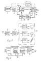
- FIG. 1, 1 designates a receiving module which obtains text data from a number of serial interfaces which are indicated by input arrows which are not identified.
- the text data define the identity, location, type (font number) and size of characters as well as setting commands, especially end-of-line commands.
- the text data can be output by input devices, not shown, in particular other computer systems or memories, such as floppy disks. Details of the text data and their input means can be found in DE-PS 29 40 897 (US Pat. No. 4,231,096).
- the input means can also include an input terminal with a keyboard and a display screen or a data transmission channel such as a telephone line.
- An input device 2 for character-specific data also belongs to the area exposer.
- Character-specific data are, in particular, data which define the contour or outline of each character of a character set, as well as width values (thicknesses) of the corresponding characters. Further details on the character-specific data can be found in DE-PS 29 40 897.
- Input devices for character-specific data belong to the prior art and are referred to in particular as "font handlers".
- the input device can obtain the font-specific data from font storage means, which are in particular designed as a floppy disk.
- the input device which is designed as a "font handler”
- can be connected to a floppy disk drive device which is not shown in FIG. 1.
- An essential component of a conventional imagesetter is an output data processing system, which is denoted by 4 in FIG. 1.
- the output data processing system is fed by the receiving module 1 with text data via a text memory 5, in which the text data of various serially fed setting tasks (jobs) are stored in an orderly manner.
- the text data arrive in the output data processing system 4 via an input 6.
- the output data processing system receives character-specific data from the input device 2 via an input 7.
- Conventional output data systems use the text data and the character-specific data to generate output data which are suitable for controlling a modulator of the scanning beam, the deflection movement of the scanner and the drive device.
- video signals can be obtained from the output data with which a laser beam is switched on and off or intensity-modulated as a scanning beam.
- third digital data are generated as output data from the text data and character-specific data, which are also referred to as first and second digital data.
- the output data processing system contains in particular a processor and data memory.
- the output data processing system can be embodied with a data management subsystem which provides data for a contour conversion subsystem in order to facilitate rapid processing of the data provided by the contour conversion subsystem.
- the contour conversion subsystem places stored ones in particular Outlines or contour data, ie character-specific data taking into account the text data into horizontal line data for the laser scanner.
- the horizontal line data is pixel data as essential output data.
- the output data memory is designated by 8 in FIG. 1.
- the output data processing system 4 contains, in addition to the X register, a Y register, in which data in the Y direction can be fed in according to the height of scanning lines or character spacing in the Y direction.
- a laser scanner 10 is connected to the output data memory 8, which records the output data, in particular pixel data, along scan lines, via a scan interface 9.
- the scanning interface 9 is controlled by control data from the output data system 4 and from the laser scanner 10 so that the pixel data are converted into video control signals for modulating the light modulator 11 in the laser scanner, with which pixels on the recording medium 12 are modulated.
- the scanning interface 9 outputs control signals for starting the drive device 13 of the recording medium.
- a scanning drive 14 for a scanning polygon 15 is also connected to the scanning interface so that the rotational speed of the polygon mirror is synchronized with the drive device of the recording medium.
- the polygon mirror 15 is driven by a motor 16 which is fed from a PLL controller 17.
- the drive of the polygon mirror is speed-controlled with the PLL controller.
- angle of rotation pulses from an angle of rotation pulse generator 19 are fed to the motor 16 via the pulse shaper 20 into an actual value input of the PLL controller.
- a setpoint input of this controller is fed with pulses from an adjustable frequency divider 21, which are derived from a frequency generator 22.
- the PLL controller regulates a constant speed of the motor 19 and the polygon mirror, which emits a scanning beam or
- Beams 23 are deflected over a scanning line 24.
- the recording medium 12 can be transported with a stepper motor 24 at a constant speed in the feed direction 25.
- a speed and position control device, generally designated 26 feeds a pulse of constant pulse frequency into the stepping motor 24, which is generated by the frequency generator or clock generator 22.
- the movement of the motor 16 which drives the polygon mirror is therefore synchronized with the feed caused by the stepping motor 24.
- a reference signal SOL from a pulse shaper 27 is also used, which is connected to a photosensitive element 27a which detects a specific position of the scanning beam 23 on the recording medium.
- the laser scanner also includes an optical system, which essentially consists of an aplanatic single lens 28, a field-flattening mirror 29, a deflecting line mirror 30 and an objective lens 31 and a diverging lens 23, which is a character projected into an intermediate image plane 33, i.e. Expose the pixels of the character on the recording medium 12.
- an optical system which essentially consists of an aplanatic single lens 28, a field-flattening mirror 29, a deflecting line mirror 30 and an objective lens 31 and a diverging lens 23, which is a character projected into an intermediate image plane 33, i.e. Expose the pixels of the character on the recording medium 12.
- FIG. 5 shows, by projecting the deflection movement of the polygon mirror onto the recording medium 12, the latter can be scanned over the width of the set and exposed imagewise over the width of a text.
- the scanning lines are designated Z1, Z2.
- the scanning lines run in a straight line and at a constant distance from each other approximately at right angles to the feed direction. (The slight inclination of the scanning lines is based on the finite scanning speed in relation to the feed speed of the recording medium.)
- the direction of advance of the record carrier is the Y direction, while the scanning movement is perpendicular to the X direction. It can be seen from FIG.
- the described imagesetter has the following components:
- a text decoder 34 is provided, which feeds the text data from the text memory either directly into the input 6 of the output data processing system 4 or into a converter 35.
- a text segmenter 36 can be interposed between the corresponding output of the text decoder and the input of the converter.
- the text data of the text to be exposed are fed into the text decoder 34 from the text memory 5, as are character-specific data, which are the widths (Dickten) of the characters to be exposed contain, from the input device 2 character-specific data. This data is used to determine whether the text to be exposed exceeds a predetermined length to width ratio and falls below the predetermined setting width by a predetermined amount. If these criteria are met, the converter 35 is activated by an output signal of the text decoder to rotate the text to be exposed by 90 ° with respect to a normal position of the text on the recording medium.
- the text decoder contains additional logic 34a, into which additional information can be fed in, which is intended to preclude a text rotation. For this purpose, an input 37 of the text decoder can be fed in in particular in the user command. Information about image data contained in the text, which likewise precludes rotation of the text to be set, can be obtained from the text data.
- the activated converter receives 38 text data and character-specific data at its input, from which transformed data are generated by the construction of the converter, which cause the text to be exposed to be rotated by 90 ° to its normal position during conventional processing of the converted data in the output data processing system.
- This transformed data is also referred to as rotation X distance data and rotation Y distance data.
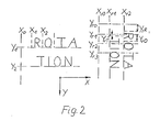
- Corresponding X-distance data in the X-direction which are denoted by X0, X1 and X2, include distances between a left writing edge of the record carrier and the left side edge of the first character or plus the width values (thicknesses) of the subsequent characters that immediately follow connect the preceding character.
- the converter transforms the described Y distance data Y 1, Y 2 into rotary X distance data, which can also be related to the left writing edge, as shown in the right part for a text rotated by 90 ° to the normal position.
- the rotation X distance data are referred to as X r1 , X r2 .
- the distance between the rotation X distance data X r1 and X r2 corresponds to the line spacing between Y1 and Y2 in the text in the normal position.
- a rotary grid with rotary grid lines Y r0 , Y r1 , Y r2 etc. is superimposed on this to form the rotary Y distance data of the text rotated by 90 °.
- the rotary grid lines run in the X direction.
- the rotation Y distance date Y rR is now determined.
- the corresponding distances Y rT and Y r0 of the following characters are related to the rotary grid lines Y r1 .
- as many character spacings as possible are referenced to each rotary grid line, e.g. the spacing of the two characters T and 0 on Y r1 .
- the text data and character-specific data are output by the converter 35 in the form:
- the data described last, including the rotary Y data is fed via a line 39 from the converter into the Y register 40 in the output data processing system.
- the rotational X distance data flows via line 41 into the X register 42 in the output data processing system.
- the data stored in the X-register and the Y-register can then be used as a basis for the further functional and computing sequence.
- the left side edge or the left writing edge X r0 is equal to the normal left writing edge X0 and that the rotation X- Distance date X r1 can be freely selected.
- the position of the uppermost rotary grid line Y r1 can be freely selected, which is followed by the following rotary grid lines at constant intervals.
- the character data and the character-specific data of this text can be transformed directly. If, however, the length of the text to be rotated is the setting width exceeds, the text data and text-specific data are first divided into segments in a text segmenter upstream of the converter, in such a way that the segments rotated with the converter, which are to be exposed, take up the entire setting width as far as possible, but do not exceed it.
- the text segmenter thus contains comparison criteria for the width and length of the text to be set. For the rest, this text segmenter works in principle in a similar way to known text segmenters, in which, however, the text is split up to put the segments next to one another.
- the present text segmenter contains a logic 36a which precludes segmentation of the text along cutting lines which intersect image grids (structures) or borders, ie relocates the segmentation to areas of the text in which such image grids or borders do not occur. This deviates from the criterion mentioned at the beginning that the text segments take up the entire setting width.
- a section line along which the text which exceeds a predetermined length corresponding to the setting width is segmented is indicated by a broken line in FIG. 5 and designated by 43.
- FIG. 5 shows how a text column 44 is conventionally exposed on the recording medium 12 using the area exposer when the text is not to be rotated.
- the scanning movement runs in the direction of the lines or, in other words, in the direction of the width of the characters.
- the record carrier is transported transversely to it in the feed direction 25. It can be seen from FIG. 5 that a relatively large area remains in the right part of the record carrier, which area is not exposed with scanning lines Z1 and Z2.
- FIG. 6 shows how the text rotated by 90 ° with respect to the normal position fills the setting width of the record carrier. Above the rotated text column 45 shown, further rotated text columns or non-rotated text can then follow, which largely uses the area of the recording medium.
- FIG. 6 clearly shows the areal exposure method by which the record carrier is advanced in the line direction of the text, while at the same time the record carrier is scanned in the direction of the height of the text, so that the scanning lines Z1 and Z2 over the length of the text or of a text segment.
- the feed direction is in the direction of the width of the text or the characters that form the text.
- FIG. 3 shows a hardware implementation of part of the platesetter:
- a central processor unit 46 with serial channels, a main memory 47 designed as RAM and the output data memory 7 - compare also FIG. 1 - are in data-exchanging connection via a system bus 48.
- the central processor 46 and the main memory form a process computer which, according to its virtual structure, forms the process modules described for the reception module 1, the text memory 5, the text decoder 34, the converter 35, the text segmenter 36 and the output data processing system 4.
- the output data memory 7 and the scanning interface connected to it form the laser scanner interface logic, which enters into data exchange with the drive device and the scan drive and outputs video control data to the modulator, see FIG. 1.
- the drive device 13 in FIG. 1 corresponds to the motor 24 and the speed and position controller 26 in FIG. 4.
Landscapes
- Engineering & Computer Science (AREA)
- Physics & Mathematics (AREA)
- Theoretical Computer Science (AREA)
- General Physics & Mathematics (AREA)
- General Engineering & Computer Science (AREA)
- Computational Linguistics (AREA)
- General Health & Medical Sciences (AREA)
- Health & Medical Sciences (AREA)
- Audiology, Speech & Language Pathology (AREA)
- Artificial Intelligence (AREA)
- Optics & Photonics (AREA)
- Record Information Processing For Printing (AREA)
- Printers Or Recording Devices Using Electromagnetic And Radiation Means (AREA)
- Manufacturing Optical Record Carriers (AREA)
- Controls And Circuits For Display Device (AREA)
- Mechanical Optical Scanning Systems (AREA)
Priority Applications (1)
| Application Number | Priority Date | Filing Date | Title |
|---|---|---|---|
| AT87104141T ATE59337T1 (de) | 1986-04-30 | 1987-03-20 | Flaechenbelichter zum flaechenmaessigen belichten von text auf einem aufzeichnungstraeger, sowie verfahren zum flaechenmaessigen belichten. |
Applications Claiming Priority (2)
| Application Number | Priority Date | Filing Date | Title |
|---|---|---|---|
| DE19863614645 DE3614645A1 (de) | 1986-04-30 | 1986-04-30 | Flaechenbelichter zum flaechenmaessigen belichten von text auf einem aufzeichnungstraeger, sowie verfahren zum flaechenmaessigen belichten |
| DE3614645 | 1986-04-30 |
Publications (2)
| Publication Number | Publication Date |
|---|---|
| EP0243659A1 true EP0243659A1 (fr) | 1987-11-04 |
| EP0243659B1 EP0243659B1 (fr) | 1990-12-27 |
Family
ID=6299868
Family Applications (1)
| Application Number | Title | Priority Date | Filing Date |
|---|---|---|---|
| EP87104141A Expired - Lifetime EP0243659B1 (fr) | 1986-04-30 | 1987-03-20 | Dispositif d'exposition de surface pour exposer un texte sur un support d'enregistrement et méthode pour faire une telle exposition |
Country Status (4)
| Country | Link |
|---|---|
| US (1) | US4821048A (fr) |
| EP (1) | EP0243659B1 (fr) |
| AT (1) | ATE59337T1 (fr) |
| DE (2) | DE3614645A1 (fr) |
Cited By (1)
| Publication number | Priority date | Publication date | Assignee | Title |
|---|---|---|---|---|
| WO1996034745A3 (fr) * | 1995-05-04 | 1996-12-19 | Hell Ag Linotype | Procede et dispositif d'exposition a la lumiere |
Families Citing this family (4)
| Publication number | Priority date | Publication date | Assignee | Title |
|---|---|---|---|---|
| JP3130034B2 (ja) * | 1990-11-28 | 2001-01-31 | 株式会社東芝 | 画像形成装置 |
| SE502083C2 (sv) * | 1991-05-28 | 1995-08-07 | Misomex Ab | Förfarande och anordning för automatiserad exponering av ljuskänsligt material medelst laserljus |
| SE504487C2 (sv) * | 1995-05-03 | 1997-02-24 | Misomex Ab | Kopieringsmaskin med fixerat inställbar laserenhet |
| US6151152A (en) * | 1999-12-21 | 2000-11-21 | Xerox Corporation | Reference frequency and facet to facet error correction circuit |
Citations (2)
| Publication number | Priority date | Publication date | Assignee | Title |
|---|---|---|---|---|
| US4300206A (en) * | 1977-06-30 | 1981-11-10 | International Business Machines Corporation | Flexible text and image generator for a raster printer |
| US4331955A (en) * | 1980-08-07 | 1982-05-25 | Eltra Corporation | Method and apparatus for smoothing outlines |
Family Cites Families (3)
| Publication number | Priority date | Publication date | Assignee | Title |
|---|---|---|---|---|
| JPS5734285A (en) * | 1980-08-06 | 1982-02-24 | Fujitsu Ltd | Printer output system |
| JPS5878297A (ja) * | 1981-11-02 | 1983-05-11 | 日本電気株式会社 | メ−タセンサ |
| US4698648A (en) * | 1984-03-22 | 1987-10-06 | Canon Kabushiki Kaisha | Image recording method and apparatus such as a light beam multiformat camera |
-
1986
- 1986-04-30 DE DE19863614645 patent/DE3614645A1/de not_active Withdrawn
-
1987
- 1987-03-20 AT AT87104141T patent/ATE59337T1/de not_active IP Right Cessation
- 1987-03-20 EP EP87104141A patent/EP0243659B1/fr not_active Expired - Lifetime
- 1987-03-20 DE DE8787104141T patent/DE3767016D1/de not_active Expired - Fee Related
-
1988
- 1988-08-03 US US07/228,855 patent/US4821048A/en not_active Expired - Fee Related
Patent Citations (2)
| Publication number | Priority date | Publication date | Assignee | Title |
|---|---|---|---|---|
| US4300206A (en) * | 1977-06-30 | 1981-11-10 | International Business Machines Corporation | Flexible text and image generator for a raster printer |
| US4331955A (en) * | 1980-08-07 | 1982-05-25 | Eltra Corporation | Method and apparatus for smoothing outlines |
Non-Patent Citations (2)
| Title |
|---|
| PATENT ABSTRACTS OF JAPAN, Band 6, Nr. 100 (P-121)[978], 9. Juni 1982; & JP-A-57 034 285 (FUJITSU K.K.) 24.02.1982 * |
| PATENT ABSTRACTS OF JAPAN, Band 7, Nr. 172 (P-213)[1317], 29. Juli 1983; & JP-A-58 078 279 (NIHON DEJITARU KENKYUSHO K.K.) 11.05.1983 * |
Cited By (2)
| Publication number | Priority date | Publication date | Assignee | Title |
|---|---|---|---|---|
| WO1996034745A3 (fr) * | 1995-05-04 | 1996-12-19 | Hell Ag Linotype | Procede et dispositif d'exposition a la lumiere |
| US5898453A (en) * | 1995-05-04 | 1999-04-27 | Linotype-Hell Ag | Method and apparatus for exposing recording material having a temperature compensated optical isolator |
Also Published As
| Publication number | Publication date |
|---|---|
| US4821048A (en) | 1989-04-11 |
| EP0243659B1 (fr) | 1990-12-27 |
| DE3614645A1 (de) | 1987-11-05 |
| ATE59337T1 (de) | 1991-01-15 |
| DE3767016D1 (de) | 1991-02-07 |
Similar Documents
| Publication | Publication Date | Title |
|---|---|---|
| DE2729114C2 (de) | Verfahren und Vorrichtung zur Reproduktion von Bild- und Textmaterial | |
| DE2060661C3 (de) | Verfahren zum Herstellen einer Fläche in Form eines Reliefs sowie Vorrichtung zur Durchführung des Verfahrens | |
| DE3215276C2 (de) | Tintenstrahldrucker | |
| DE69418910T2 (de) | Verfahren zur Herstellung einer positiven lithographischen Druckplatte | |
| DE69221780T2 (de) | Tintenstrahlaufzeichnungsgerät | |
| DE2758139C3 (de) | Schaltung zur Umordnung von Bilddaten | |
| DE3417195C2 (fr) | ||
| EP0163850B1 (fr) | Procédé et dispositif de synchronisation d'une bande de matériau, en particulier une bande de matériau photosensible, dans un système de photocomposition | |
| DE69230161T2 (de) | Bildaufzeichnungsvorrichtung | |
| DE3038374A1 (de) | Verfahren zur erzeugung eines layouts von bildern, die nach originalbildern auf ein fotoempfindliches material reproduziert werden | |
| DE60222065T2 (de) | Aufzeichnungsgerät mit mehreren Aufzeichnungsköpfen und Aufzeichnungssystem mit diesem Aufzeichnungsgerät | |
| DE3430559A1 (de) | Druckaufbereitungsgeraet zum aufbereiten reproduzierter bilder | |
| DE2360657C3 (de) | Steuerschaltung für einen Gleichstrommotor | |
| DE3328215C2 (de) | Verfahren zur Korrektur der Bildverzerrung bei Bildern, die mittels eines Bildwiedergabesystems reproduziert werden | |
| DE69029359T2 (de) | Verfahren und Gerät zur Umformattierung von Druckdaten | |
| DE3428101C2 (fr) | ||
| DE3112275C2 (de) | Kopierverfahren und Kopiergerät | |
| EP0243659B1 (fr) | Dispositif d'exposition de surface pour exposer un texte sur un support d'enregistrement et méthode pour faire une telle exposition | |
| DE69620923T2 (de) | Verfahren zum unschädlichen Unterdrücken benachbarter Punkte beim hochauflösenden Bilddruck | |
| DE69422540T2 (de) | Gerät und Verfahren zur Erzeugung einer gerasterten Bildreproduktion | |
| DE69230549T2 (de) | Drucker zum Drucken von fetten Buchstaben | |
| DE68922158T2 (de) | Datenverarbeitungsvorrichtung. | |
| DE69117929T2 (de) | Druckverfahren in blattdrucker | |
| DE3337582A1 (de) | Verfahren und vorrichtung zur wiedergabe eines halbtonbilds durch abtasten | |
| DE69424490T2 (de) | Laserdrucksystem |
Legal Events
| Date | Code | Title | Description |
|---|---|---|---|
| PUAI | Public reference made under article 153(3) epc to a published international application that has entered the european phase |
Free format text: ORIGINAL CODE: 0009012 |
|
| AK | Designated contracting states |
Kind code of ref document: A1 Designated state(s): AT CH DE GB LI |
|
| RIN1 | Information on inventor provided before grant (corrected) |
Inventor name: THIESSEN, HANS-HENNING Inventor name: HORNIG, KLAUS-JUERGEN |
|
| 17P | Request for examination filed |
Effective date: 19880108 |
|
| RAP1 | Party data changed (applicant data changed or rights of an application transferred) |
Owner name: LINOTYPE AG |
|
| 17Q | First examination report despatched |
Effective date: 19890321 |
|
| GRAA | (expected) grant |
Free format text: ORIGINAL CODE: 0009210 |
|
| AK | Designated contracting states |
Kind code of ref document: B1 Designated state(s): AT CH DE GB LI |
|
| REF | Corresponds to: |
Ref document number: 59337 Country of ref document: AT Date of ref document: 19910115 Kind code of ref document: T |
|
| REF | Corresponds to: |
Ref document number: 3767016 Country of ref document: DE Date of ref document: 19910207 |
|
| GBT | Gb: translation of ep patent filed (gb section 77(6)(a)/1977) | ||
| PLBE | No opposition filed within time limit |
Free format text: ORIGINAL CODE: 0009261 |
|
| STAA | Information on the status of an ep patent application or granted ep patent |
Free format text: STATUS: NO OPPOSITION FILED WITHIN TIME LIMIT |
|
| 26N | No opposition filed | ||
| PGFP | Annual fee paid to national office [announced via postgrant information from national office to epo] |
Ref country code: AT Payment date: 19930218 Year of fee payment: 7 |
|
| PGFP | Annual fee paid to national office [announced via postgrant information from national office to epo] |
Ref country code: CH Payment date: 19930315 Year of fee payment: 7 |
|
| PGFP | Annual fee paid to national office [announced via postgrant information from national office to epo] |
Ref country code: GB Payment date: 19940207 Year of fee payment: 8 |
|
| PGFP | Annual fee paid to national office [announced via postgrant information from national office to epo] |
Ref country code: DE Payment date: 19940222 Year of fee payment: 8 |
|
| PG25 | Lapsed in a contracting state [announced via postgrant information from national office to epo] |
Ref country code: AT Effective date: 19940320 |
|
| PG25 | Lapsed in a contracting state [announced via postgrant information from national office to epo] |
Ref country code: LI Effective date: 19940331 Ref country code: CH Effective date: 19940331 |
|
| REG | Reference to a national code |
Ref country code: CH Ref legal event code: PL |
|
| PG25 | Lapsed in a contracting state [announced via postgrant information from national office to epo] |
Ref country code: GB Effective date: 19950320 |
|
| GBPC | Gb: european patent ceased through non-payment of renewal fee |
Effective date: 19950320 |
|
| PG25 | Lapsed in a contracting state [announced via postgrant information from national office to epo] |
Ref country code: DE Effective date: 19951201 |