EP0243680B1 - Dispositif d'éclairage sur fond clair - Google Patents
Dispositif d'éclairage sur fond clair Download PDFInfo
- Publication number
- EP0243680B1 EP0243680B1 EP87104442A EP87104442A EP0243680B1 EP 0243680 B1 EP0243680 B1 EP 0243680B1 EP 87104442 A EP87104442 A EP 87104442A EP 87104442 A EP87104442 A EP 87104442A EP 0243680 B1 EP0243680 B1 EP 0243680B1
- Authority
- EP
- European Patent Office
- Prior art keywords
- incident
- lens
- rays
- image converter
- housing
- Prior art date
- Legal status (The legal status is an assumption and is not a legal conclusion. Google has not performed a legal analysis and makes no representation as to the accuracy of the status listed.)
- Expired - Lifetime
Links
Images
Classifications
-
- G—PHYSICS
- G02—OPTICS
- G02B—OPTICAL ELEMENTS, SYSTEMS OR APPARATUS
- G02B21/00—Microscopes
- G02B21/06—Means for illuminating specimens
- G02B21/08—Condensers
- G02B21/082—Condensers for incident illumination only
-
- G—PHYSICS
- G01—MEASURING; TESTING
- G01N—INVESTIGATING OR ANALYSING MATERIALS BY DETERMINING THEIR CHEMICAL OR PHYSICAL PROPERTIES
- G01N21/00—Investigating or analysing materials by the use of optical means, i.e. using sub-millimetre waves, infrared, visible or ultraviolet light
- G01N21/84—Systems specially adapted for particular applications
- G01N21/88—Investigating the presence of flaws or contamination
- G01N21/8806—Specially adapted optical and illumination features
Definitions
- the invention relates to a device for illuminating the object surface of an object to be detected by an image converter, in particular when recognizing tinned structures on printed circuit boards.
- an illumination unit can also be used, which consists of four external inclined fiber-optic light sources and a Fresnel lens and is intended to result in maximum sharpness and maximum working distance at a fixed angle of incidence.
- the components are removed from a placement head from the corresponding feeds and then placed in the specified placement positions on the circuit boards centered in the assembly area.
- the position of corresponding adjustment structures on the printed circuit board should be recognized with the aid of semiconductor cameras and image analysis systems.
- a position detection leads to unsatisfactory results both with incident incident vertical light and with incident incident oblique light.
- only a part of the tinned conductor tracks or adjustment structures is exactly captured by the semiconductor camera and correctly evaluated in the image analysis system.
- the invention has for its object to provide a device for incident light illumination of the object surface of an object to be detected by an image converter, with which a glare-free and shadow-free illumination of the structures is made possible even with printed circuit boards with tinned conductor tracks or adjustment structures.
- This object is achieved in a generic device for incident light illumination by simultaneous exposure of the object surface to vertically incident rays and rays which are incident obliquely on all sides.
- the invention is based on the finding that structures with spherical and planar surfaces can be produced in the circuit board by tinning and that the object surfaces are illuminated in such a way that spherical and planar surfaces are the same by a suitable combination of vertical and obliquely incident light from all angles at a large solid angle be mapped.
- the flat or spherical tinned structures are always displayed brightly on a dark background and with sharp contours.
- the detection of a structure, such as. B. a connecting pad or an alignment mark can then be made easily with the same detection rule even with different surface properties of the circuit boards.
- the perpendicularly incident rays can be generated in a particularly simple manner in that laterally incident light can be directed perpendicularly onto the object surface by a beam splitter in the direction of the objective axis of the image converter.
- the beam splitter is preferably arranged below the lens of the image converter.
- the rays which are incident obliquely on all sides can be directed to the object surface via a lens having a central opening which is coaxial to the lens axis.
- the lens which is preferably in the form of a Fresnel lens, enables light to be incident on all sides at a large solid angle, while the central opening ensures the undisturbed passage of the vertical rays.
- the rays which are obliquely incident on all sides can be directed to the object surface via a diffusing screen with a central opening lying coaxially to the lens axis.
- a diffusing screen with a central opening lying coaxially to the lens axis.
- the lens or the lens forms the lower end of a circular cylindrical housing with a mirrored inner wall, at least in the casing of the housing a light source can be used. Due to the mirrored inner wall, the light from a single light source already leads through the frequent reflections to a largely uniform, circular distribution of the light and accordingly to an oblique incidence of light on all sides.
- the lens barrel of the image converter projects coaxially into the housing.
- the outer surface of the lens barrel is mirrored and the annular, uniform distribution of the light is thus further promoted.
- the housing, the lens barrel, the beam splitter and the lens or the diffusing screen form a unit which can be attached to the image converter as an attachment.
- This unit can then, for example, be screwed into a corresponding thread of the camera instead of the original lens barrel of a semiconductor camera.
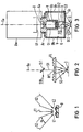
- 0 denotes an object, which is to be a printed circuit board with tin-plated conductor tracks or adjustment structures.
- a uniform, glare-free and shadow-free illumination of such spherical and flat surfaces is achieved by the simultaneous exposure of the surface of the object 0 with vertically incident rays S1 and with obliquely incident rays S2 on all sides.
- the angle designated a between the rays S2 incident obliquely on all sides should be so large that the illumination aperture is at least equal to the observation aperture of the image converter used.
- FIG. 2 shows, purely schematically, a first possibility for generating the perpendicularly incident rays S1 and the incidently oblique rays S2.
- laterally incident light S10 is formed by a beam splitter St1 designed as a partially transparent mirror in the direction of the objective axis Oa of an image converter not shown in FIG. 2 and through the central opening Of1 of a Fresnel lens FL onto the surface of the Object 0 directed.
- the Fresnel lens FL consists of a central part in the form of a normal thin lens with the central opening Of1 and of annular zones which surround the central part and which all have the same focal point and approximately the same thickness as the central part.
- the beams S1 are formed, for example, by the corresponding beam deflection from above, which strikes the Fresnel lens FL perpendicularly.
- FIG. 3 shows an image converter Bw designed as a semiconductor camera or CCD camera, the light-sensitive surface of which is designated by LF with the elements arranged in rows and columns.
- the thread attachment Ga of a circular cylindrical, hollow housing G is screwed into the thread for the normal lens barrel, a stop ring Ar being clamped between the image converter Bw and the housing G.
- a diaphragm B for telecentric beam path is introduced in the area of the threaded attachment Ga, with an objective tube Ot with an objective Ob being connected to this diaphragm B at the bottom.
- the lens barrel Ot projects coaxially into the housing G, i. that is, the housing G is accordingly also coaxially aligned with the lens axis Oa of the image converter Bw.
- the lower end of the circular-cylindrical housing G is formed by a diffusing screen Ss made of frosted glass, which has a central opening Of2 which is coaxial with the lens axis Oa.
- a beam splitter St2 designed as a beam splitter cube, which deflects light S10 incident laterally from one direction perpendicularly onto the surface of the object, the vertically incident rays as already shown in FIGS. 1 and 2 S1 are designated.
- the jacket of the housing G there are bores Bh on opposite sides, into which halogen lamps, not shown in FIG. 3, are used as light sources.
- the inner wall of the housing G and the outer surface of the lens barrel Ot are mirrored, the mirroring being indicated by the reference symbol V. Because of this mirror coating V, which is also applied to three side surfaces of the beam splitter St2, the light generated by the light sources is reflected so often that the rays S2 incident obliquely on all sides on the surface of the object 0 pass through the diffusing screen Ss.
- the light sources also ensure that they enter the beam splitter from the side due to the diverse reflections St2 incident light S10, ie no separate light source is required to generate the perpendicularly incident rays S1.
- the Fresnel lens FL shown in FIG. 2 can also be used instead of the diffusing screen Ss.
- the image converter Bw shown in FIG. 3 with the device for incident-light illumination designed as an attachment is used for the automatic assembly of printed circuit boards.
- adjustment structures on the printed circuit boards are recognized, so that the movements of the placement head when the components are set down can be corrected automatically in accordance with the positional deviations of the printed circuit board that may have been found.
Landscapes
- Physics & Mathematics (AREA)
- Analytical Chemistry (AREA)
- General Physics & Mathematics (AREA)
- Chemical & Material Sciences (AREA)
- General Health & Medical Sciences (AREA)
- Biochemistry (AREA)
- Life Sciences & Earth Sciences (AREA)
- Health & Medical Sciences (AREA)
- Immunology (AREA)
- Pathology (AREA)
- Optics & Photonics (AREA)
- Investigating Materials By The Use Of Optical Means Adapted For Particular Applications (AREA)
- Supply And Installment Of Electrical Components (AREA)
- Length Measuring Devices By Optical Means (AREA)
Claims (10)
Applications Claiming Priority (2)
| Application Number | Priority Date | Filing Date | Title |
|---|---|---|---|
| DE3613750 | 1986-04-23 | ||
| DE3613750 | 1986-04-23 |
Publications (3)
| Publication Number | Publication Date |
|---|---|
| EP0243680A1 EP0243680A1 (fr) | 1987-11-04 |
| EP0243680B1 true EP0243680B1 (fr) | 1991-04-03 |
| EP0243680B2 EP0243680B2 (fr) | 1994-04-13 |
Family
ID=6299353
Family Applications (1)
| Application Number | Title | Priority Date | Filing Date |
|---|---|---|---|
| EP87104442A Expired - Lifetime EP0243680B2 (fr) | 1986-04-23 | 1987-03-25 | Dispositif d'éclairage sur fond clair |
Country Status (2)
| Country | Link |
|---|---|
| EP (1) | EP0243680B2 (fr) |
| DE (1) | DE3769000D1 (fr) |
Cited By (1)
| Publication number | Priority date | Publication date | Assignee | Title |
|---|---|---|---|---|
| DE10012043A1 (de) * | 2000-03-14 | 2001-10-04 | Bosch Gmbh Robert | Vorrichtung zur Ausrichtung von Referenzmarken tragenden Objekten zueinander |
Families Citing this family (5)
| Publication number | Priority date | Publication date | Assignee | Title |
|---|---|---|---|---|
| US4929845A (en) * | 1989-02-27 | 1990-05-29 | At&T Bell Laboratories | Method and apparatus for inspection of substrates |
| US5197105A (en) * | 1990-05-30 | 1993-03-23 | Dainippon Screen Mfg. Co. Ltd. | Method of reading optical image of inspected surface and image reading system employabale therein |
| FR2675903A1 (fr) * | 1991-04-26 | 1992-10-30 | Dicom | Dispositif de detection des defauts d'un joint d'etancheite annulaire, et procede de controle d'un tel joint a l'aide de ce dispositif. |
| US6359694B1 (en) | 1997-11-10 | 2002-03-19 | Siemens Aktiengesellschaft | Method and device for identifying the position of an electrical component or terminals thereof, and equipping head employing same |
| EP3850341B1 (fr) * | 2018-09-13 | 2024-11-27 | University Of Massachusetts | Système et procédés d'éclairage par fluorescence libre dichroïque utilisant des lentilles d'objectif réfléchissantes |
Family Cites Families (3)
| Publication number | Priority date | Publication date | Assignee | Title |
|---|---|---|---|---|
| DE2542075A1 (de) * | 1975-09-20 | 1977-07-21 | Leitz Ernst Gmbh | Auflicht-beleuchtungseinrichtung fuer hell- und dunkelfeldbeleuchtung |
| DD138110A1 (de) * | 1978-07-27 | 1979-10-10 | Horst Riesenberg | Auflicht-beleuchtungseinrichtung fuer mikroskope |
| JPS5828712A (ja) * | 1981-08-13 | 1983-02-19 | Olympus Optical Co Ltd | 暗視野照明用光学系 |
-
1987
- 1987-03-25 EP EP87104442A patent/EP0243680B2/fr not_active Expired - Lifetime
- 1987-03-25 DE DE8787104442T patent/DE3769000D1/de not_active Expired - Lifetime
Cited By (1)
| Publication number | Priority date | Publication date | Assignee | Title |
|---|---|---|---|---|
| DE10012043A1 (de) * | 2000-03-14 | 2001-10-04 | Bosch Gmbh Robert | Vorrichtung zur Ausrichtung von Referenzmarken tragenden Objekten zueinander |
Also Published As
| Publication number | Publication date |
|---|---|
| EP0243680A1 (fr) | 1987-11-04 |
| EP0243680B2 (fr) | 1994-04-13 |
| DE3769000D1 (de) | 1991-05-08 |
Similar Documents
| Publication | Publication Date | Title |
|---|---|---|
| DE69415965T2 (de) | Verfahren und vorrichtung zur kontinuierlichen diffusen beleuchtung | |
| DE69102941T2 (de) | Strahlungsthermometer. | |
| DE3119688C2 (fr) | ||
| EP0047936A1 (fr) | Procédé et dispositif pour le contrôle photo-électrique de structures superficielles sur des corps à symétrie de rotation | |
| DE69409299T2 (de) | Lichtquelle-Vorrichtung für Bildverarbeitungsgerät | |
| EP1532479A1 (fr) | Dispositif et procede pour inspecter un objet | |
| DE102016111600B4 (de) | Beleuchtungsanordnung | |
| EP0243680B2 (fr) | Dispositif d'éclairage sur fond clair | |
| EP1031026B1 (fr) | dispositif permettant de detecter la position des composants, dispositif pour la deviation lumineuse et tete pour l'implantation automatique de composants | |
| DE4035799A1 (de) | Optische vorrichtung mit konfokalem strahlengang zur dreidimensionalen untersuchung eines objektes | |
| DE4426968C2 (de) | Optische Untersuchungsvorrichtung | |
| DE19731545C1 (de) | Vorrichtung und Verfahren zum optischen Erfassen der Verformung einer Fläche | |
| EP0098521A1 (fr) | Procédé et dispositif de commutation automatique pour l'éclairage d'une pièce | |
| DE102022207871A1 (de) | Überprüfungsvorrichtung | |
| EP0800756B1 (fr) | Dispositif de reconnaissance de la position des connexions de composants | |
| EP0336114B1 (fr) | Dispositif de détection de la position des plots de contact de composants électriques ou électroniques | |
| DE2242644B2 (de) | Optische Abtastvorrichtung | |
| DE3249685C2 (fr) | ||
| EP1456602B1 (fr) | Capteur de detection visuelle de position (composant, substrat) dote d'une unite d'eclairage modulaire | |
| DE4142108C2 (de) | Montagestruktur für ein optisches Bauteil einer Optikeinrichtung | |
| DE4134299A1 (de) | Optischer sensor mit einer ausrichtvorrichtung | |
| DE4124003C2 (de) | Beleuchtungseinrichtung zum Beleuchten von klar-transparenten Prüfobjekten, für die Untersuchung der Prüfobjekte auf Fehler | |
| DE68908351T2 (de) | Verfahren und Vorrichtung zur Prüfung des Randes eines Deckels. | |
| WO1995012809A1 (fr) | Systeme d'eclairage et de reproduction d'image | |
| EP4165394B1 (fr) | Dispositif de mesure et procédé pour la mesure d'une réflectivité d'éléments optiques revêtus |
Legal Events
| Date | Code | Title | Description |
|---|---|---|---|
| PUAI | Public reference made under article 153(3) epc to a published international application that has entered the european phase |
Free format text: ORIGINAL CODE: 0009012 |
|
| AK | Designated contracting states |
Kind code of ref document: A1 Designated state(s): CH DE GB LI |
|
| 17P | Request for examination filed |
Effective date: 19880205 |
|
| 17Q | First examination report despatched |
Effective date: 19900308 |
|
| GRAA | (expected) grant |
Free format text: ORIGINAL CODE: 0009210 |
|
| AK | Designated contracting states |
Kind code of ref document: B1 Designated state(s): CH DE GB LI |
|
| REF | Corresponds to: |
Ref document number: 3769000 Country of ref document: DE Date of ref document: 19910508 |
|
| GBT | Gb: translation of ep patent filed (gb section 77(6)(a)/1977) | ||
| K2C3 | Correction of patent specification (complete document) published |
Effective date: 19910403 |
|
| PLBI | Opposition filed |
Free format text: ORIGINAL CODE: 0009260 |
|
| 26 | Opposition filed |
Opponent name: LEICA INDUSTRIEVERWALTUNG GMBH, WETZLAR KONZERNSTE Effective date: 19911227 |
|
| PUAH | Patent maintained in amended form |
Free format text: ORIGINAL CODE: 0009272 |
|
| STAA | Information on the status of an ep patent application or granted ep patent |
Free format text: STATUS: PATENT MAINTAINED AS AMENDED |
|
| 27A | Patent maintained in amended form |
Effective date: 19940413 |
|
| AK | Designated contracting states |
Kind code of ref document: B2 Designated state(s): CH DE GB LI |
|
| REG | Reference to a national code |
Ref country code: CH Ref legal event code: AEN |
|
| GBTA | Gb: translation of amended ep patent filed (gb section 77(6)(b)/1977) |
Effective date: 19940622 |
|
| REG | Reference to a national code |
Ref country code: GB Ref legal event code: IF02 |
|
| PGFP | Annual fee paid to national office [announced via postgrant information from national office to epo] |
Ref country code: GB Payment date: 20060308 Year of fee payment: 20 |
|
| PGFP | Annual fee paid to national office [announced via postgrant information from national office to epo] |
Ref country code: DE Payment date: 20060522 Year of fee payment: 20 |
|
| PGFP | Annual fee paid to national office [announced via postgrant information from national office to epo] |
Ref country code: CH Payment date: 20060613 Year of fee payment: 20 |
|
| PG25 | Lapsed in a contracting state [announced via postgrant information from national office to epo] |
Ref country code: GB Free format text: LAPSE BECAUSE OF EXPIRATION OF PROTECTION Effective date: 20070324 |
|
| REG | Reference to a national code |
Ref country code: CH Ref legal event code: PL |