EP0243779A1 - Maschine zum Abrollen, Aufstellen und Befestigen von Fertigrasen auf dem Boden - Google Patents
Maschine zum Abrollen, Aufstellen und Befestigen von Fertigrasen auf dem Boden Download PDFInfo
- Publication number
- EP0243779A1 EP0243779A1 EP87105467A EP87105467A EP0243779A1 EP 0243779 A1 EP0243779 A1 EP 0243779A1 EP 87105467 A EP87105467 A EP 87105467A EP 87105467 A EP87105467 A EP 87105467A EP 0243779 A1 EP0243779 A1 EP 0243779A1
- Authority
- EP
- European Patent Office
- Prior art keywords
- conveyor belt
- grass
- machine according
- machine
- chassis
- Prior art date
- Legal status (The legal status is an assumption and is not a legal conclusion. Google has not performed a legal analysis and makes no representation as to the accuracy of the status listed.)
- Withdrawn
Links
- 239000002689 soil Substances 0.000 title 1
- 244000025254 Cannabis sativa Species 0.000 claims abstract description 29
- XEEYBQQBJWHFJM-UHFFFAOYSA-N Iron Chemical compound [Fe] XEEYBQQBJWHFJM-UHFFFAOYSA-N 0.000 claims description 4
- 229910052742 iron Inorganic materials 0.000 claims description 2
- 229910052751 metal Inorganic materials 0.000 claims description 2
- 239000002184 metal Substances 0.000 claims description 2
- 230000000284 resting effect Effects 0.000 claims 1
- 230000005484 gravity Effects 0.000 description 2
- 229910052782 aluminium Inorganic materials 0.000 description 1
- XAGFODPZIPBFFR-UHFFFAOYSA-N aluminium Chemical compound [Al] XAGFODPZIPBFFR-UHFFFAOYSA-N 0.000 description 1
- 238000000151 deposition Methods 0.000 description 1
- 235000000396 iron Nutrition 0.000 description 1
- 230000002250 progressing effect Effects 0.000 description 1
- 238000005096 rolling process Methods 0.000 description 1
- 239000000523 sample Substances 0.000 description 1
- 238000005507 spraying Methods 0.000 description 1
- 230000001360 synchronised effect Effects 0.000 description 1
- 239000002023 wood Substances 0.000 description 1
Images


Classifications
-
- A—HUMAN NECESSITIES
- A01—AGRICULTURE; FORESTRY; ANIMAL HUSBANDRY; HUNTING; TRAPPING; FISHING
- A01G—HORTICULTURE; CULTIVATION OF VEGETABLES, FLOWERS, RICE, FRUIT, VINES, HOPS OR SEAWEED; FORESTRY; WATERING
- A01G20/00—Cultivation of turf, lawn or the like; Apparatus or methods therefor
- A01G20/10—Pre-cultivated sod or turf; Apparatus therefor
- A01G20/12—Apparatus for cutting sods or turfs
- A01G20/15—Apparatus for cutting sods or turfs specially adapted for stacking sods or sod rolls
-
- A—HUMAN NECESSITIES
- A01—AGRICULTURE; FORESTRY; ANIMAL HUSBANDRY; HUNTING; TRAPPING; FISHING
- A01G—HORTICULTURE; CULTIVATION OF VEGETABLES, FLOWERS, RICE, FRUIT, VINES, HOPS OR SEAWEED; FORESTRY; WATERING
- A01G20/00—Cultivation of turf, lawn or the like; Apparatus or methods therefor
- A01G20/10—Pre-cultivated sod or turf; Apparatus therefor
- A01G20/18—Apparatus for laying sods or turfs
-
- Y—GENERAL TAGGING OF NEW TECHNOLOGICAL DEVELOPMENTS; GENERAL TAGGING OF CROSS-SECTIONAL TECHNOLOGIES SPANNING OVER SEVERAL SECTIONS OF THE IPC; TECHNICAL SUBJECTS COVERED BY FORMER USPC CROSS-REFERENCE ART COLLECTIONS [XRACs] AND DIGESTS
- Y10—TECHNICAL SUBJECTS COVERED BY FORMER USPC
- Y10S—TECHNICAL SUBJECTS COVERED BY FORMER USPC CROSS-REFERENCE ART COLLECTIONS [XRACs] AND DIGESTS
- Y10S111/00—Planting
- Y10S111/901—Lawn or turf
-
- Y—GENERAL TAGGING OF NEW TECHNOLOGICAL DEVELOPMENTS; GENERAL TAGGING OF CROSS-SECTIONAL TECHNOLOGIES SPANNING OVER SEVERAL SECTIONS OF THE IPC; TECHNICAL SUBJECTS COVERED BY FORMER USPC CROSS-REFERENCE ART COLLECTIONS [XRACs] AND DIGESTS
- Y10—TECHNICAL SUBJECTS COVERED BY FORMER USPC
- Y10S—TECHNICAL SUBJECTS COVERED BY FORMER USPC CROSS-REFERENCE ART COLLECTIONS [XRACs] AND DIGESTS
- Y10S414/00—Material or article handling
- Y10S414/124—Roll handlers
Definitions
- the present invention relates to machines for assembling and laying on the ground rolls of precultivated grass, for sports grounds for example.
- US-A 4,408,666 (LAWSON) relates to an apparatus for directing lawn to the ground, comprising a storage tray and a raceway.
- the patent US-A 3 982 711 (BRADLEY) relates to a machine for placing the turf, comprising a tray made up of several conveyor belts which pour the plates between vertical belts by means of a rotary element with fingers.
- the present invention overcomes these drawbacks in that the operators and the rolls of grass are carried by the machine and this in particular eliminates the handling of planks, in addition, allows significant time savings.
- the machine object of the invention comprises a chassis which can be self-propelled or semi-carried.
- This chassis is preferably fitted with wide low-pressure tires 07, so that the pressure exerted on the ground is not more than 0.500 Kg / cm 2, so as not to compress the ground too much.
- Said frame carries a tray, pivoting with any suitable means, on which is placed a pallet of grass rolls, to facilitate its unloading by an operator being on a neighboring tray.
- the operator takes the rolls of grass, one by one, and places them on a waiting cradle, which rolls take place on a conveyor belt which deposits them on the ground on an inclined plane.
- the grass plate is sandwiched by two conveyor belts so as to allow effective positioning against the row previously laid on the ground.
- the speed of the treadmills is adjusted in relation to the speed of the machine. Near the end of the treadmill close to the ground is placed a mechanical cutter which works the surface part of the ground and a small sprinkler placed behind moistens the layer of earth turned over.
- the lower end of the treadmill is held against the plates of the previously positioned row, by means of a guide, by means of a suitable system.
- the rear of the machine carries a platform for an operator and pulls a roller which carries a watering ramp, which is supplied by a hose connected to a supply point located in the field.
- the front end of the machine can be provided with a guide which is in contact with the outer edge of the last row of the turf patch. This guide can be fitted with a probe which acts directly on the direction of the machine.
- the means for routing the lawn to the ground can be partially constituted with conveyor belts offered on the market.
- the machine comprises a longitudinal chassis 1 carried by wide tires 2 at low pressure and towed by an engine enclosed in a cockpit 3, which chassis 1 carries from front to rear on the right side, looking towards the rear , a platform 4 for placing a first operator within reach of which is a plate 5 supporting a pallet 6 loaded with rollers 7 of grass and further behind the plate 5 is another platform 8 supporting a second operator, then that on the left side of the chassis 1 are positioned-) born the elements which allow the routing and the placing of the grass on the ground.
- the plate 5 is carried by a pivoting axis 9 which is actuated by a small electric motor 10 whose speed is adjusted relative to the advancement of the machine, in order to present to the operator the rollers 7 of turf placed at the opposite on the pallet.
- the electric motor can be powered by accumulator batteries.
- the lawn transport elements comprise a longitudinal plate 11 carried by a pivoting axis 12, on which plate 11 is fixed a conveyor belt 13 which is juxtaposed by its rear end to an inclined chute 14 which has its lower end taken between two belts 15 and 17 fixed and maintained in a box 16, which box 16 has its part bordering the ground provided with a mechanical cutter 22 (as found in trade) and a sprinkler 18, and the lower end of said box 16 has a guide 19.
- the chute 14 consists of a metal plate forming the bottom and has lateral flanges 20 for guiding the grass plates which descend by gravity.
- the chute 14 is articulated at its upper end on the plate II by means of two rods provided with rotary means such as movable bearings (not shown), and said chute is maneuvered in its middle part by means of a jack 21 fixed on the frame 1, which jack 21 makes it possible to vary the inclination of the chute 14, according to the specifics grass patches, as well as lifting the lower end of the incline at the end of the row to maneuver.
- the front end of the treadmill 13 is surmounted by a hoop consisting of two parallel arcs 23 positioned on either side of the mat, which arcs 23 are carried by jacks 24 which retract downwards depositing the roller 7 of grass on the carpet 13 which brings it towards the rear, which roller 7 of grass abuts against a small conveyor belt 25 placed vertically and directly above the carpet 13, which carpet 25 has its part in contact which turns from the bottom up causing the roll 7 to unwind backwards, which roll 7 extends progressively over the belt 13 which carries it to the upper end of the chute 14.
- a second conveyor belt 26 also placed directly above the carpet 13 but in the horizontal direction, takes the sandwiched lawn up to the chute 14.
- the jacks 24 retract at a regular rate which is set to the speed of laying the lawn patches on the ground.
- the conveyor belts 25 and 26 are fixed by any appropriate means to the plate 11.
- a spring 27 fixed by one end to the chassis 1 has its other end fixed to the side of the trough 14, holding the latter against the row 28 of grass previously pressed to the ground, through the guide 19.
- the guide 19 is constituted (see FIG. 4) of a rectangular plate 30 positioned horizontally, one longitudinal side of which has a flange 31 oriented downwards and one end 32 is bent upwards.
- the plate 30 is juxtaposed to the box 16 by the side, by means of fixing plates 33, which plate 30 slides on the row 28 of turf and by its rim 31 presses against the edge 29 of the turf so that the plates being poses are well adjusted to the previous row.
- the guide 19 may be provided with a feeler (not shown) which would act directly on the means making the axis 12 pivot which carries the plate II on which the horizontal conveyor belts are positioned, in order to permanently correct the fitting of the plates of grass.
- a vibrating plate 34 fixed by any suitable means to the chassis 1, is positioned in the extension of the box 16 to adjust the grass plates as and when they are laid.
- the rear of the chassis pulls a roller 35 which carries a spraying boom 36 connected by a pipe 37 to a supply mouth (not shown).
- the roller 35 rolls continuously on the last three strips of turf laid.
- a guide 38 provided with a feeler (not shown) is in contact with the row of grass previously laid on the ground, making it possible to correct, by means of appropriate means, the direction of advance of the machine.
- the conveyor belts 13, 15, 17, 25 and 26 have their speeds synchronized with one another by means of regulators and timers, as well as with respect to the advance of the machine.
- FIG. 5 represents a simplified embodiment of the machine in that the conveyor belts have been eliminated, therefore the roller 7 of grass is unrolled manually on the plate 11, then pushed onto the inclined chute 14, on which it descends by gravity to on the ground.
- the lower end of the trough 14 carries the mechanical cutter 22, the sprinkler 18 and a guide 38 consisting of a simple vertical plate, which has its lower part which pushes on the edge 29 of the row 28 of the laid lawn, under the pressure of a spring 27 pressing on the plate 39 fixed on said chute.
- an operator carried by the platform 8 manually adjusts the turf plates on the ground.
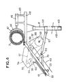
- Figures 6, 7, 8, 9 and 10 show another alternative embodiment, according to the invention comprising an upper plate 40 carried by means of a vertical beam 41 which slides in a second vertical beam 42 connected to the chassis by a horizontal beam 43, on which plate is placed a roller 7 of grass which is brought by means of a cradle 44 operated by a jack 45, up to a vertical conveyor belt 46 placed on the upper part of the inclined plane.
- the cradle 44 is constituted by a curved sheet which is positioned on a vertical plane, so as to present the curved side 47 facing the roller 7 of grass, to allow it to slide to the carpet 46 without deforming it.
- the cradle 44 is actuated, by its curved side, by means of the jack 45 which is fixed on a horizontal plane by means of two flanges 48 for fixing on the upper plate 40.
- the roller 7 of grass pushed by the cradle 44 arrives at the inclined plane which is formed by a conveyor belt 49 driven by pulleys 50 and 51, which pulleys are fixed on a longitudinal frame 52 reinforced by transverse sections 53.
- flanges 54 At the upper end of the inclined plane, on the lateral sides of the frame 52 are fixed two flanges 54, in opposite manner, which flanges 54 carry two superimposed pulleys 55 and 56 which drive the conveyor belt 46 making it possible to undo the roller 7 of grass .
- the pulleys 55 and 56 and the conveyor belt 49 are actuated with the engine of the machine by means of known means such as: chains 57, pinion 58 and pin 59.
- a rod 60 At the height of the pulley 56 and transversely to the inclined plane, a rod 60 is fixed by its ends to the flanges 54, which rod 60 retains, by means of a rotary fastener, a longitudinal piece 61 positioned on the center of the conveyor belt 49 of said inclined plane.
- This longitudinal piece 61 makes it possible, by its inertia, due to its weight, to keep the turf clad on the treadmill and to avoid any heap.
- Part 61 can be made of wood, aluminum, etc.
- Figure 8 shows a mechanical cutter b? positioned under the inclined plane and connected to the chassis 63 of the machine by an articulated arm 64 which is raised by a jack 65.
- the mechanical cutter 62 is actuated by a small electric motor 66 and can be paired with a roller not shown.
- the inclined plane is operated with a jack 67 fixed by one end 3 to the vertical beam 42 by means of a flange 68 and by its rod on a cross-member 69 placed under the conveyor belt 49 and fixed by two lateral brackets 70 to the frame 52.
- the automatic guiding of the machine is carried out by means of a shoe fixed to the lower end of the inclined plane, by any suitable means, which shoe is maintained in permanent support, with a controlled effort, on the strip of grass previously asked.
- On the circular beam 41, carrying the upper plate 40 are fixed a cam 71 and two electrical contacts 72, one of which is actuated, depending on whether the inclined plane shifts to the right or the left, causing the supply of one of the two chambers of the machine's steering cylinder.
- the cam 71 consists of a curved iron secured to the beam 41 by means of two flat irons 73 and a circular flange 74.
- the electrical contacts 72 are carried by a plate 75 fixed by means of a bracket 76 to the lower beam 42.
Landscapes
- Life Sciences & Earth Sciences (AREA)
- Environmental Sciences (AREA)
- Transplanting Machines (AREA)
- Soil Working Implements (AREA)
- Cultivation Of Plants (AREA)
- Agricultural Machines (AREA)
Applications Claiming Priority (4)
| Application Number | Priority Date | Filing Date | Title |
|---|---|---|---|
| FR8606566A FR2597701B1 (fr) | 1986-04-25 | 1986-04-25 | Machine pour derouler, assembler et plaquer sur le sol des rouleaux de gazon precultive. |
| FR8606566 | 1986-04-25 | ||
| FR8704341 | 1987-03-20 | ||
| FR878704341A FR2612360B1 (fr) | 1987-03-20 | 1987-03-20 | Machine pour juxtaposer et plaquer sur le sol des rouleaux de gazon precultive |
Publications (1)
| Publication Number | Publication Date |
|---|---|
| EP0243779A1 true EP0243779A1 (de) | 1987-11-04 |
Family
ID=9334992
Family Applications (1)
| Application Number | Title | Priority Date | Filing Date |
|---|---|---|---|
| EP87105467A Withdrawn EP0243779A1 (de) | 1986-04-25 | 1987-04-13 | Maschine zum Abrollen, Aufstellen und Befestigen von Fertigrasen auf dem Boden |
Country Status (7)
| Country | Link |
|---|---|
| US (1) | US4777890A (de) |
| EP (1) | EP0243779A1 (de) |
| JP (1) | JPS62289104A (de) |
| AU (1) | AU588101B2 (de) |
| CA (1) | CA1318186C (de) |
| ES (1) | ES2008051A4 (de) |
| FR (1) | FR2597701B1 (de) |
Cited By (7)
| Publication number | Priority date | Publication date | Assignee | Title |
|---|---|---|---|---|
| FR2695534A1 (fr) * | 1992-09-11 | 1994-03-18 | Sodiape | Machine à déposer le gazon. |
| FR2716333A1 (fr) * | 1994-02-24 | 1995-08-25 | Fontainebleau Gazons | Dispositif de pose de gazon précultivé en bandes. |
| WO1995035021A1 (en) * | 1994-06-17 | 1995-12-28 | Gräscenter I Eskilstuna Ab | A production method for lawn sod rolls and a device to perform the method |
| FR2730125A1 (fr) * | 1995-02-07 | 1996-08-09 | Belle Jacques | Dispositif pour derouler au sol au moins un rouleau de gazon |
| US5626195A (en) * | 1995-07-10 | 1997-05-06 | Bucyrus Equipment Co.. Inc. | Sod harvesting system |
| US6364027B1 (en) * | 2000-06-26 | 2002-04-02 | Donald Tvetene | Sod harvester |
| CN107027524A (zh) * | 2017-05-09 | 2017-08-11 | 何宏昌 | 一种园林用草坪输送铺设装置 |
Families Citing this family (33)
| Publication number | Priority date | Publication date | Assignee | Title |
|---|---|---|---|---|
| NL187512C (nl) * | 1987-12-02 | 1991-11-01 | Hendriks Vof Research Geb | Werkwijze voor het transporteren van graszoden met behulp van een van een aantal tanden voorziene vork en van tanden voorziene vork bestemd voor het uitvoeren van een dergelijke werkwijze. |
| CA2026473C (en) * | 1989-09-29 | 2002-01-15 | Stuart Paul Mail | Turf handling machine |
| JPH03191705A (ja) * | 1989-12-18 | 1991-08-21 | Kubota Corp | 芝張り機 |
| US5269379A (en) * | 1990-11-07 | 1993-12-14 | Red Hen Turf Farm Inc. | Automated sod harvesting apparatus |
| JPH0576213A (ja) * | 1991-09-17 | 1993-03-30 | Sanyo Shibafu Kk | 芝茎点植方法及びその装置 |
| US5215278A (en) * | 1991-12-02 | 1993-06-01 | Hess Douglas S | Apparatus for laying turf |
| US5988289A (en) * | 1997-08-04 | 1999-11-23 | Holland; Gregory Paul | Sod laying apparatus |
| US6131668A (en) * | 1997-12-29 | 2000-10-17 | Clark Equipment Company | Sod laying apparatus and method |
| US6213218B1 (en) * | 1998-10-22 | 2001-04-10 | Donald R. Miller | Sod laying apparatus |
| US6135211A (en) * | 1999-02-04 | 2000-10-24 | Schroeder; Roger A. | Gopher sod cutter and baller |
| US6550406B2 (en) | 2001-03-21 | 2003-04-22 | Anthony C. Bass | Sod roll installation device |
| US7096967B2 (en) * | 2002-07-15 | 2006-08-29 | Steiner Turf Equipment, Inc. | Robotic sod stacker with software control |
| US7070004B2 (en) * | 2002-07-15 | 2006-07-04 | Steiner Turf Equipment, Inc. | Robotic sod stacker |
| US7188447B2 (en) * | 2004-03-15 | 2007-03-13 | Sherron & Rose, Llc | Machine for laying ground cover on seeded areas |
| US7740083B2 (en) * | 2007-07-23 | 2010-06-22 | Trebro Holding Co., Inc. | Sod harvesting apparatus |
| US9056572B2 (en) * | 2011-12-15 | 2015-06-16 | North Texas Tollway Authority | Safety cone and barrell placement and retrieval apparatus |
| US9028199B2 (en) * | 2012-01-25 | 2015-05-12 | Lawns Keeper Inc. | Sod positioning machine |
| HUE055853T2 (hu) * | 2015-04-24 | 2022-01-28 | Sidekick Usa Llc | Gyepszõnyeg pozicionáló gép |
| US9688476B1 (en) * | 2016-05-02 | 2017-06-27 | Trebro Manufacturing, Inc | Sod harvester |
| CN107401154A (zh) * | 2016-05-20 | 2017-11-28 | 北京林业大学 | 多杆横向推草装置 |
| US10701872B1 (en) * | 2017-11-02 | 2020-07-07 | Tre Bro Holding, Inc | Sod harvesters |
| CN109964739B (zh) * | 2019-04-03 | 2021-03-12 | 陈昱成 | 一种堤坝岸边铺草装置 |
| CN110972648B (zh) * | 2019-12-03 | 2023-06-23 | 农业农村部南京农业机械化研究所 | 一种高效有序抛秧机取苗机构及方法 |
| US11111088B2 (en) * | 2020-01-13 | 2021-09-07 | Firefly Automatix, Inc. | Sod roll stacking technique |
| CN111519493B (zh) * | 2020-04-30 | 2021-08-03 | 北京天仁科技发展有限公司 | 一种草坪植丝机 |
| CN114287214B (zh) * | 2021-12-28 | 2022-07-19 | 农业农村部南京农业机械化研究所 | 一种党参种苗装订收卷机构及其方法 |
| CN114271148B (zh) * | 2022-01-14 | 2022-11-25 | 赵梅 | 一种园林绿化施工用绿化草皮铺设装置 |
| CN115529876B (zh) * | 2022-04-15 | 2026-04-03 | 浙江理工大学 | 一种智能固沙机器人 |
| CN114766291B (zh) * | 2022-05-09 | 2023-09-29 | 张家港江苏科技大学产业技术研究院 | 一种草皮铺设装置 |
| CN114667892A (zh) * | 2022-05-30 | 2022-06-28 | 潍坊科技学院 | 一种园林草皮铺埋设备 |
| CN115633602B (zh) * | 2022-11-30 | 2024-04-19 | 陕西中泾渭达水利工程设计有限公司 | 一种水土保持工程草皮铺设装置及铺设方法 |
| AU2024256073A1 (en) * | 2023-04-14 | 2025-11-27 | Paul Carlson | Selectable sod positioning machine |
| CN119655125B (zh) * | 2025-01-22 | 2025-09-16 | 中国科学院西北生态环境资源研究院 | 一种冻土区生态修复用植被毯铺设装置及其铺设方法 |
Citations (3)
| Publication number | Priority date | Publication date | Assignee | Title |
|---|---|---|---|---|
| US3982711A (en) * | 1975-04-09 | 1976-09-28 | Bradley Frank M | Sod laying machine |
| US4149640A (en) * | 1976-06-07 | 1979-04-17 | White John M | Means for laying sod |
| US4408666A (en) * | 1981-10-28 | 1983-10-11 | Lawson Charles L | Sod handling apparatus |
Family Cites Families (9)
| Publication number | Priority date | Publication date | Assignee | Title |
|---|---|---|---|---|
| US474425A (en) * | 1892-05-10 | Planter | ||
| US965980A (en) * | 1909-09-10 | 1910-08-02 | George E Autry | Transplanting-machine. |
| US964820A (en) * | 1910-01-13 | 1910-07-19 | Frank H Snyder | Mint-planter. |
| US2633256A (en) * | 1949-05-03 | 1953-03-31 | Borden Mills Inc | Lap handling apparatus |
| US3159121A (en) * | 1964-05-12 | 1964-12-01 | Jr Martin L Beck | Grass planter |
| US4145980A (en) * | 1976-12-06 | 1979-03-27 | A. Duda And Sons Inc. | Seeder for planting seeds at precise intervals |
| US4073388A (en) * | 1977-01-06 | 1978-02-14 | Zetco Manufacturing Company, Incorporated | Semi-automatic lifting system |
| CA1138781A (en) * | 1979-07-20 | 1983-01-04 | Brouwer Turf Equipment Limited | Automatic steering mechanism for sod processing machine and shoe therefor |
| US4289080A (en) * | 1979-07-25 | 1981-09-15 | Celanese Corporation | High-speed transplanter |
-
1986
- 1986-04-25 FR FR8606566A patent/FR2597701B1/fr not_active Expired
-
1987
- 1987-04-13 ES ES87105467T patent/ES2008051A4/es active Pending
- 1987-04-13 EP EP87105467A patent/EP0243779A1/de not_active Withdrawn
- 1987-04-21 US US07/040,619 patent/US4777890A/en not_active Expired - Fee Related
- 1987-04-23 CA CA000535433A patent/CA1318186C/fr not_active Expired - Fee Related
- 1987-04-24 JP JP62101717A patent/JPS62289104A/ja active Pending
- 1987-04-24 AU AU71976/87A patent/AU588101B2/en not_active Ceased
Patent Citations (3)
| Publication number | Priority date | Publication date | Assignee | Title |
|---|---|---|---|---|
| US3982711A (en) * | 1975-04-09 | 1976-09-28 | Bradley Frank M | Sod laying machine |
| US4149640A (en) * | 1976-06-07 | 1979-04-17 | White John M | Means for laying sod |
| US4408666A (en) * | 1981-10-28 | 1983-10-11 | Lawson Charles L | Sod handling apparatus |
Cited By (10)
| Publication number | Priority date | Publication date | Assignee | Title |
|---|---|---|---|---|
| FR2695534A1 (fr) * | 1992-09-11 | 1994-03-18 | Sodiape | Machine à déposer le gazon. |
| WO1994006270A1 (fr) * | 1992-09-11 | 1994-03-31 | Societe De Developpement De L'industrie Agro-Alimentaire Et De La Pepiniere Europeenne - Sodiape | Machine a deposer le gazon |
| FR2716333A1 (fr) * | 1994-02-24 | 1995-08-25 | Fontainebleau Gazons | Dispositif de pose de gazon précultivé en bandes. |
| WO1995035021A1 (en) * | 1994-06-17 | 1995-12-28 | Gräscenter I Eskilstuna Ab | A production method for lawn sod rolls and a device to perform the method |
| FR2730125A1 (fr) * | 1995-02-07 | 1996-08-09 | Belle Jacques | Dispositif pour derouler au sol au moins un rouleau de gazon |
| EP0726023A1 (de) * | 1995-02-07 | 1996-08-14 | Jacques Belle | Vorrichtung um Rasensoden auf den Boden zu entrollen |
| US5626195A (en) * | 1995-07-10 | 1997-05-06 | Bucyrus Equipment Co.. Inc. | Sod harvesting system |
| US6364027B1 (en) * | 2000-06-26 | 2002-04-02 | Donald Tvetene | Sod harvester |
| CN107027524A (zh) * | 2017-05-09 | 2017-08-11 | 何宏昌 | 一种园林用草坪输送铺设装置 |
| CN107027524B (zh) * | 2017-05-09 | 2020-03-31 | 新昌县水帘峡市政园林有限公司 | 一种园林用草坪输送铺设装置 |
Also Published As
| Publication number | Publication date |
|---|---|
| US4777890A (en) | 1988-10-18 |
| JPS62289104A (ja) | 1987-12-16 |
| CA1318186C (fr) | 1993-05-25 |
| FR2597701A1 (fr) | 1987-10-30 |
| ES2008051A4 (es) | 1989-07-16 |
| FR2597701B1 (fr) | 1989-03-24 |
| AU7197687A (en) | 1987-10-29 |
| AU588101B2 (en) | 1989-09-07 |
Similar Documents
| Publication | Publication Date | Title |
|---|---|---|
| EP0243779A1 (de) | Maschine zum Abrollen, Aufstellen und Befestigen von Fertigrasen auf dem Boden | |
| FR2590312A1 (fr) | Dispositif de fixation de bandes d'espacement flexibles sur des plaques de verre | |
| FR2492743A1 (fr) | Machine pour le montage automatique de pneumatiques sur des jantes | |
| CA1182135A (fr) | Procede et installation de mise en paquets de tuyaux en fonte a emboitement | |
| FR2626264A3 (fr) | Appareil de distribution et d'enroulement de revetements de sol | |
| EP0244308A1 (de) | Maschine zum Aufnehmen und Stapeln von geschnittenen Bögen | |
| FR2460598A1 (fr) | Machine a recolter les plantes en rang par traction sur leurs feuilles ou tiges | |
| FR2556924A1 (fr) | Appareil de manoeuvre et de deplacement de baches pour la recolte des fruits | |
| FR2522245A1 (fr) | Materiel agricole pour la recolte de fruits et ensembles recepteurs constitutifs dudit materiel | |
| EP0389321B1 (de) | Ballensammelgerät | |
| EP1222845B1 (de) | Verfahren zum Trennen eckiger Setzlinge, Gerät zum Ausführen des Verfahrens und Pflanzmaschine mit einem solchen Gerät zum Pflanzen von Setzlingen | |
| FR2483736A1 (fr) | Faucheuse | |
| BE1005088A6 (fr) | Procede et appareil pour tailler des plantes en pots, notamment des azalees. | |
| FR2480720A1 (fr) | Perfectionnement aux dispositifs d'empilage de plaques | |
| EP0465327A2 (de) | Vorrichtung für die Errichtung von Kulturtunneln | |
| FR2716333A1 (fr) | Dispositif de pose de gazon précultivé en bandes. | |
| FR2740294A1 (fr) | Systeme de cueillette de choux brocolis | |
| FR2555455A1 (fr) | Procede de ramassage d'objets de forme spherique et dispositif permettant sa mise en oeuvre | |
| FR2749003A1 (fr) | Machine destinee au debardage des caisses de fruits pendant la recolte ou la cueillette dans les plantations | |
| FR2766504A1 (fr) | Machine pour la depose de plaques de gazon notamment sur des terrains de sports | |
| FR2484193A1 (fr) | Machine permettant l'enlevement des arceaux de tunnels de culture ainsi que leur mise en place | |
| FR2612360A2 (fr) | Machine pour juxtaposer et plaquer sur le sol des rouleaux de gazon precultive | |
| JP3608087B2 (ja) | 自走式根菜収穫機 | |
| FR2685167A1 (fr) | Procede et dispositif pour charger en garniture et rouler des rouleaux de printemps. | |
| FR2507654A1 (fr) | Procede de construction d'un mur par assemblage d'elements de construction, notamment de parpaings, et dispositif pour la mise en oeuvre du procede |
Legal Events
| Date | Code | Title | Description |
|---|---|---|---|
| PUAI | Public reference made under article 153(3) epc to a published international application that has entered the european phase |
Free format text: ORIGINAL CODE: 0009012 |
|
| AK | Designated contracting states |
Kind code of ref document: A1 Designated state(s): AT BE CH DE ES GB GR IT LI LU NL SE |
|
| 17P | Request for examination filed |
Effective date: 19880125 |
|
| 17Q | First examination report despatched |
Effective date: 19890908 |
|
| TCNL | Nl: translation of patent claims filed | ||
| STAA | Information on the status of an ep patent application or granted ep patent |
Free format text: STATUS: THE APPLICATION IS DEEMED TO BE WITHDRAWN |
|
| 18D | Application deemed to be withdrawn |
Effective date: 19931026 |