EP0243782A2 - Pupitre de commande d'opérations - Google Patents
Pupitre de commande d'opérations Download PDFInfo
- Publication number
- EP0243782A2 EP0243782A2 EP87105482A EP87105482A EP0243782A2 EP 0243782 A2 EP0243782 A2 EP 0243782A2 EP 87105482 A EP87105482 A EP 87105482A EP 87105482 A EP87105482 A EP 87105482A EP 0243782 A2 EP0243782 A2 EP 0243782A2
- Authority
- EP
- European Patent Office
- Prior art keywords
- operation control
- control desk
- push
- screen
- controlled
- Prior art date
- Legal status (The legal status is an assumption and is not a legal conclusion. Google has not performed a legal analysis and makes no representation as to the accuracy of the status listed.)
- Ceased
Links
Images





Classifications
-
- G—PHYSICS
- G06—COMPUTING OR CALCULATING; COUNTING
- G06F—ELECTRIC DIGITAL DATA PROCESSING
- G06F17/00—Digital computing or data processing equipment or methods, specially adapted for specific functions
-
- G—PHYSICS
- G05—CONTROLLING; REGULATING
- G05B—CONTROL OR REGULATING SYSTEMS IN GENERAL; FUNCTIONAL ELEMENTS OF SUCH SYSTEMS; MONITORING OR TESTING ARRANGEMENTS FOR SUCH SYSTEMS OR ELEMENTS
- G05B19/00—Program-control systems
- G05B19/02—Program-control systems electric
- G05B19/04—Program control other than numerical control, i.e. in sequence controllers or logic controllers
- G05B19/10—Program control other than numerical control, i.e. in sequence controllers or logic controllers using selector switches
- G05B19/106—Program control other than numerical control, i.e. in sequence controllers or logic controllers using selector switches for selecting a program, variable or parameter
- G05B19/108—Program control other than numerical control, i.e. in sequence controllers or logic controllers using selector switches for selecting a program, variable or parameter characterised by physical layout of switches; switches co-operating with display; use of switches in a special way
-
- G—PHYSICS
- G06—COMPUTING OR CALCULATING; COUNTING
- G06F—ELECTRIC DIGITAL DATA PROCESSING
- G06F3/00—Input arrangements for transferring data to be processed into a form capable of being handled by the computer; Output arrangements for transferring data from processing unit to output unit, e.g. interface arrangements
- G06F3/01—Input arrangements or combined input and output arrangements for interaction between user and computer
- G06F3/02—Input arrangements using manually operated switches, e.g. using keyboards or dials
- G06F3/023—Arrangements for converting discrete items of information into a coded form, e.g. arrangements for interpreting keyboard generated codes as alphanumeric codes, operand codes or instruction codes
- G06F3/0238—Programmable keyboards
-
- H—ELECTRICITY
- H02—GENERATION; CONVERSION OR DISTRIBUTION OF ELECTRIC POWER
- H02B—BOARDS, SUBSTATIONS OR SWITCHING ARRANGEMENTS FOR THE SUPPLY OR DISTRIBUTION OF ELECTRIC POWER
- H02B15/00—Supervisory desks or panels for centralised control or display
Definitions
- This invention relates to an operation control desk and more particularly to an operation control desk using a cathode ray tube (CRT) display unit which is suitable for operating a plurality of objects to be controlled without resort to additional operation control desks.
- CTR cathode ray tube
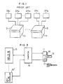
- a plurality of operation desks each connected with a plurality of units to be controlled are employed as exemplified in Fig. I wherein m controllable units 2A,, 2A z , ..., 2A m are controlled by an operation desk IA and controllable units 2N,, ..., 2Nt are 15 controlled by an operation desk IN.
- Fig. 2 illustrates a plurality of operation switches 4 respectively dedicated to the plurality of units to be controlled, and the operation switches are located on a control panel 3 of each of the operation desks IA, ..., IN shown in Fig. I.
- the plurality of operation desks IA, ..., IN are provided in this manner to comply with application purposes.
- JP-A-55-94503 discloses another type of control panel utilizing a rotary type operation switch which is switchable to desired objects to be controlled. Disadvantageously, the switching in this control panel is limited to about three stages at the most.
- an operation desk for a tandem finishing rolling mill (continuous type rolling mill) is associated with a variety of objects to be controlled including:
- a coiler for winding up a rolled sheet worked out by a finishing rolling mill in the final phase is associated with objects to be controlled including:
- a main object of this invention is to provide a multi-functional operation control desk of a standardized configuration which is compatible with a plurality of objects to be controlled, contributing to layout space reduction and cost reduction.
- Another object of this invention is to facilitate control of objects to be controlled by using a single operation control desk in a multi-functional mode in which one function can be automatically switched to another by using various automating signals.
- the same operation switch is used to function differently in compliance with units to be controlled.
- a push-button switch is used as the operation switch
- a CRT unit is provided for displaying a function of the push-button switch
- a function name picture of the push-button switch is displayed on the CRT screen.
- the function of the push-button switch and the function name picture on the CRT screen can both be switched or changed using ten keys as CRT picture change operation switches.
- the function of the push-button switch once set for that object can automatically be switched to a function complying with another object to be controlled.
- the CRT unit of the general-purpose operation control desk can display, for example, function name pictures corresponding to 25 push-button switches arranged in matrix of 5 rows and 5 columns.
- function name pictures corresponding to 25 push-button switches arranged in matrix of 5 rows and 5 columns.
- the operation control desk is associated with a plurality of units to be controlled as shown in Fig. 3.
- the operation control desk as designated by reference numeral II has an operation switch board or control panel 12 on which push-button switches and the like are situated. Signals from CRT display change selecting switches and a signal from a push-button switch are fetched by a signal transmission unit 13 and then sent to a computer 14. The computer 14 extracts from the signals sent thereto the signal from the push-button switch to deliver a control signal to specified one of the plurality of controllable units 15, 15' while recognizing the CRT display change signals, and sets a display on the screen of a CRT unit 16 mounted on the operation control desk II and a function of the push-button switch is accordance with the inputted signals.
- a rolling mill, a generator (of heat power, water power or atomic power) and a water treatment plant stand for the unit to be controlled.
- the operation control desk II of the invention shown in Fig. 3 has an exterior appearance as illustrated in Fig. 4.
- the CRT display unit 16 has a display screen 22 and the desk II has operation switches (or operation levers) 23 in the form of push-button switches, ten keys 24 indicative of "0" to "9", a screen change selecting switch 25 indicative of "IN”, scroll keys 26 indicative of "-", “-", “t” and “ " and mode selection keys 27 indicative of 0 ", 2" and 3 ".
- push-button switches 23 corresponding to displayed pictures are operated to effect predetermined operations. For example, by operating a push-button switch 23a, an operation “acceleration” can be carried out and by operating a push-button switch 23b, an operation "raising looper” can be carried out.
- the screen is switched to another screen, the pictures displayed on the renewed screen are also changed to new ones and functions of the push-button switches 23a and 23b change to those represented by the renewed pictures.
- the CRT unit 16 is mounted on the top of a console of the operation control desk II.
- the 25 push-button switches 23 have functions as indicated by pictures displayed on the screen 22 of CRT unit 16. More particularly, beginning with the left, the first column represents “screw down” with upper to lower rows representing “2-notch ascent”, “one-notch ascent”, “stop”, “one-notch descent” and “2-notch descent”, respectively, the second column represents “side/guide” and the third column represents "speed”. On the right above corner of the screen 22 of CRT unit 16, "No. 5" is displayed to indicate the contents currently displayed on the screen.
- the present invention features that the individual push-button switches 23 are allowed to have multiple functions by changing the screen 22 on the CRT unit 16 in three manners as described below.
- the three kinds of determination and change methods can be selectively changed by operating the mode selection keys 27 in Fig. 4 of which " (D “ “ T “ and 3 " may exemplarily correspond to the above methods (I), (2) and (3), respectively.
- the scrolling is classified into four types, upward scroll, downward scroll, rightward scroll and leftward scroll.
- the contents of these types of scrolling will be explained by referring to the screen 22 of CRT unit 16 shown in Fig. 4.
- Push-button switches 23 in each column are subjected to the upward scroll and downward scroll independently of push-button switches 23 in the other columns.
- the sixth row indicative of "2-notch ascent” is shifted to the fifth row
- the fifth row indicative of "one-notch descent” is shifted to the fourth row
- the fourth row indicative of "stop” is shifted to the third row
- the third row indicative of "one-notch ascent” is shifted to the second row
- the second row indicative of "2-notch ascent” is shifted to the sixth row.
- the downward scroll is converse to the upward scroll, with the second row indicative of "2-notch ascent” shifted to the third row, the third row indicative of "one-notch ascent” shifted to the fourth row, ..., and the sixth row indicative of "2-notch descent” shifted to the second row.
- the rightward scroll is for sequentially shifting columns to the right with the arrangement of rows in each column unchanged.
- the leftward scroll is converse to the rightward scroll for sequentially shifting columns to the left. with the contents of the fifth column shifted to the fourth column, the contents of the fourth column shifted to the third column, ..., and the contents of the first column shifted to the fifth column.
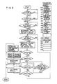
- the change method (I) by scrolling that is, the first mode of the operation control desk of this invention may be implemented as will be described below with reference to a flow chart of Fig. 5.
- the mode selection key 27 indicative of " 1 " is first depressed to designate the first mode of the operation control desk. Subsequently, the contents of each column are determined as follows. For example, to make the first column represent “screw down”, keys 24 are operated to issue “0", "I", "I". The leading "0” indicates that the display should be changed, the following "I” indicates the first column and the trailing "I” indicates that an address 100 for "screw down” in the intial frame of the character information memory should be designated.
- the computer 14 recognizes the key input "0", "I", "I” and sets the character information memory. The computer may further execute the four types of scrolling in accordance with the flow chart of Fig. 5.
- the upward scroll in the first column is effected with "0", "I", "I" of the keys 24.
- a desired value can be inputted to follow the leading "0".
- the mode selection key 27 indicative of " 2 " is depressed, as in the case of the previous first change method (I), to designate the second mode of the operation control desk, which is processed by the computer 14 shown in Fig. 3.
- the character information memory has the same structure for the previous and present methods.
- the oleration procedure is as follows. For example, to define the first row indicative of "2- notch open” in the first column representing "side/guide”, "0", “I”, “f”, “I”, “3”, “5" of the keys 24 are operated.
- the leading "0" indicates that the function of the push-button switches should be changed, the following “I” indicates the first column and the ensuing “I” indicates the first row.
- the trailing three digits indicate an address on the character information memory. Specifically, an address 135 indicates the head address for "2-notch open” in the "side/guide”.
- functions of the set of push-button switches 23 are determined for each of the objects to be controlled and recorded in the character information memory in advance, and the functions of the set of the push-button switches 23 determined for each object are represented by a screen number which makes one-to-one correspondence to an address on the character information memory.
- This third method differs from the two methods previously described in that functions of all the push-button switches are determined by one operation for keying-in a screen number.
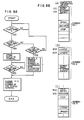
- Fig. 8A is a flow chart useful in explaining the third mode of the operation control desk of the present invention
- Fig. 8B illustrates in sections (A) through (C) patterns in the character information memory which are used for the third mode.
- the character information memory has patterns as shown at sections (A), (B) and (C) in Fig. 8B, the number of the patterns being equal to the number of screens.
- an address 100 indicates that the push-button switches on the first column function for "screw down" and an address 105 indicates that the push-button switch at the first row in the first column is for "2-notch ascent” under "screw down".
- functions of the push-button switches at the second row. third row, ... in the first column are determined. Screens numbering I to 9 are registered.
- One of screen No. I to screen No. 9 is selected through key operation.
- screen No. I can be selected by operating the key 24 of "I” and the screen change selection switch 25 indicative of "IN".
- the leading "I” indicates screen No. I and the following "IN” indicates completion of pattern selection.
- the object to be controlled changes simultaneously with the change of the screen.
- a controllable object expected to be used frequently should therefore be registered for screens of all numbers to ensure control of that object even when the screen changes.
- the screen can be changed automatically by using a signal indicative of a change in condition of the object to be controlled. This ensures that functions of push-button switches for suitable operations can be selected without requiring the operator to manually change the screen, thereby greatly reducing the time for the operator to engage himself in the apparatus.
- the arrangement of pictures in the called-up screen is predeterminedly set for each machine to be controlled and hence the user has to rearrange the pictures, as necessary. To this end, the scrolling and/or the selective change of the function of individual push-button switches is practiced.
- the rolling mill consists of a roughing mill, a crop shear, a finishing mill and a down coiler.
- the five operation control desks incorporating only 125 push-button switches in total for direct control of the machines can operate and control the rolling mill.
- the second operation control desk according to the invention serves by itself for the three machines, that is, the coarse mill, crop shear and finishing mill, thus greatly contributing to space reduction.
- two operation control desks serve for the coarse will and after completion of the rolling by the coarse mill, the second operation control desk, beginning with the left, serves for the crop shear. After completion of the crop shear operation, three intermediate operation desks serve for the finishing mill. Further, during winding-up by means of the down coiler, two operation control desks, beginning with the right, serve for the down coiler,.
- the operation control desk presently serving for the finishing mill or the coarse mill may be automatically switched to serve for the crop shear by a signal indicative of completion of rolling or a change in state of rolling, for example, completion of coarse rolling.
- a signal indicative of completion of rolling or a change in state of rolling for example, completion of coarse rolling.
- the function of the operation control desk can be automatically changed to comply with urgent operations for, for example, looper, screw down and speed, thereby making it possible to realize a one- man-operation system.
Landscapes
- Engineering & Computer Science (AREA)
- Theoretical Computer Science (AREA)
- Physics & Mathematics (AREA)
- General Engineering & Computer Science (AREA)
- General Physics & Mathematics (AREA)
- Databases & Information Systems (AREA)
- Automation & Control Theory (AREA)
- Data Mining & Analysis (AREA)
- Human Computer Interaction (AREA)
- Mathematical Physics (AREA)
- Software Systems (AREA)
- Power Engineering (AREA)
- Selective Calling Equipment (AREA)
- Eye Examination Apparatus (AREA)
- Harvester Elements (AREA)
- Centrifugal Separators (AREA)
- Programmable Controllers (AREA)
- Control Of Indicators Other Than Cathode Ray Tubes (AREA)
Applications Claiming Priority (2)
| Application Number | Priority Date | Filing Date | Title |
|---|---|---|---|
| JP100986/86 | 1986-05-02 | ||
| JP61100986A JPS62260506A (ja) | 1986-05-02 | 1986-05-02 | 運転操作デスク |
Publications (2)
| Publication Number | Publication Date |
|---|---|
| EP0243782A2 true EP0243782A2 (fr) | 1987-11-04 |
| EP0243782A3 EP0243782A3 (fr) | 1989-01-25 |
Family
ID=14288642
Family Applications (1)
| Application Number | Title | Priority Date | Filing Date |
|---|---|---|---|
| EP87105482A Ceased EP0243782A3 (fr) | 1986-05-02 | 1987-04-13 | Pupitre de commande d'opérations |
Country Status (4)
| Country | Link |
|---|---|
| EP (1) | EP0243782A3 (fr) |
| JP (1) | JPS62260506A (fr) |
| KR (1) | KR870011551A (fr) |
| FI (1) | FI871924A7 (fr) |
Cited By (9)
| Publication number | Priority date | Publication date | Assignee | Title |
|---|---|---|---|---|
| DE4008743A1 (de) * | 1990-03-19 | 1991-09-26 | Viktor Dipl Ing Schatz | Tastatur-eingabe- und anzeige-einheit mit variablen zeichensaetzen |
| EP0460676A3 (en) * | 1990-06-07 | 1992-02-26 | Omron Corporation | Set-and-display system associated with control component units |
| EP0482523A3 (en) * | 1990-10-24 | 1993-06-09 | Osaka Gas Company Limited | Multiple aspect operator interface for displaying fault diagnostics results in intelligent process control systems |
| EP0528396A3 (en) * | 1991-08-21 | 1993-07-14 | International Business Machines Corporation | Method of controlling an industrial process |
| WO1997046926A3 (fr) * | 1996-06-07 | 1998-04-02 | Amada Co Ltd | Procede et dispositif de gestion d'une machine d'usinage de plaque |
| EP1096347A1 (fr) * | 1999-10-30 | 2001-05-02 | TLC Transport-, Informatik- u. Logistik-Consulting GmbH | Intégration de différents éléments capteurs-/actuateurs dans une unité de commande unitaire |
| US6535787B1 (en) | 1996-05-10 | 2003-03-18 | Amada Company, Ltd. | Control method and apparatus for plate material processing machine |
| DE102009037165A1 (de) * | 2009-08-03 | 2011-02-17 | Stama Maschinenfabrik Gmbh | Vorrichtung zur Steuerung einer Werkzeugmaschine |
| GB2559842A (en) * | 2016-12-19 | 2018-08-22 | Hitachi Ge Nuclear Energy Ltd | User interface apparatus of display |
Family Cites Families (4)
| Publication number | Priority date | Publication date | Assignee | Title |
|---|---|---|---|---|
| US4333097A (en) * | 1980-09-12 | 1982-06-01 | Bell Telephone Laboratories, Incorporated | Visual display terminal without finger repositioning |
| US4425627A (en) * | 1981-02-23 | 1984-01-10 | Sperry Corporation | Intelligent prompting terminal apparatus |
| JPS5917630A (ja) * | 1982-07-22 | 1984-01-28 | Fanuc Ltd | デ−タ入力方式 |
| US4680728A (en) * | 1984-10-17 | 1987-07-14 | Ncr Corporation | User-friendly technique and apparatus for entering alphanumeric data through a numeric keyboard |
-
1986
- 1986-05-02 JP JP61100986A patent/JPS62260506A/ja active Pending
-
1987
- 1987-04-13 EP EP87105482A patent/EP0243782A3/fr not_active Ceased
- 1987-04-24 KR KR870003955A patent/KR870011551A/ko not_active Withdrawn
- 1987-04-30 FI FI871924A patent/FI871924A7/fi not_active Application Discontinuation
Cited By (12)
| Publication number | Priority date | Publication date | Assignee | Title |
|---|---|---|---|---|
| DE4008743A1 (de) * | 1990-03-19 | 1991-09-26 | Viktor Dipl Ing Schatz | Tastatur-eingabe- und anzeige-einheit mit variablen zeichensaetzen |
| EP0460676A3 (en) * | 1990-06-07 | 1992-02-26 | Omron Corporation | Set-and-display system associated with control component units |
| EP0482523A3 (en) * | 1990-10-24 | 1993-06-09 | Osaka Gas Company Limited | Multiple aspect operator interface for displaying fault diagnostics results in intelligent process control systems |
| US5420977A (en) * | 1990-10-24 | 1995-05-30 | Vanderbilt University | Multiple aspect operator interface for displaying fault diagnostics results in intelligent process control systems |
| EP0528396A3 (en) * | 1991-08-21 | 1993-07-14 | International Business Machines Corporation | Method of controlling an industrial process |
| US6535787B1 (en) | 1996-05-10 | 2003-03-18 | Amada Company, Ltd. | Control method and apparatus for plate material processing machine |
| WO1997046926A3 (fr) * | 1996-06-07 | 1998-04-02 | Amada Co Ltd | Procede et dispositif de gestion d'une machine d'usinage de plaque |
| EP1096347A1 (fr) * | 1999-10-30 | 2001-05-02 | TLC Transport-, Informatik- u. Logistik-Consulting GmbH | Intégration de différents éléments capteurs-/actuateurs dans une unité de commande unitaire |
| DE102009037165A1 (de) * | 2009-08-03 | 2011-02-17 | Stama Maschinenfabrik Gmbh | Vorrichtung zur Steuerung einer Werkzeugmaschine |
| EP2282246A3 (fr) * | 2009-08-03 | 2013-01-23 | STAMA Maschinenfabrik GmbH | Appareil de commande d'une machine-outil |
| GB2559842A (en) * | 2016-12-19 | 2018-08-22 | Hitachi Ge Nuclear Energy Ltd | User interface apparatus of display |
| GB2559842B (en) * | 2016-12-19 | 2020-12-30 | Hitachi Ge Nuclear Energy Ltd | User interface apparatus of display |
Also Published As
| Publication number | Publication date |
|---|---|
| FI871924A7 (fi) | 1987-11-03 |
| EP0243782A3 (fr) | 1989-01-25 |
| FI871924A0 (fi) | 1987-04-30 |
| JPS62260506A (ja) | 1987-11-12 |
| KR870011551A (ko) | 1987-12-24 |
Similar Documents
| Publication | Publication Date | Title |
|---|---|---|
| US4808987A (en) | Image data file storage and retrieval system for an image data filing system | |
| DE4115179C2 (de) | Einrichtung zum Speichern und Ausgeben von Daten in einem TV-System und Verfahren zu dessen Steuerung hierfür | |
| DE3751901T2 (de) | Einrichtung zur Benutzung in einem Computer | |
| DE69713874T2 (de) | Funktelefon | |
| US4141001A (en) | Monitor display control method and apparatus for data input unit | |
| DE10002691B4 (de) | Pegelabstimmungsanzeigevorrichtung und ein Verfahren für ein OSD-Menü bei einem Bildwiedergabegerät | |
| DE69632971T2 (de) | Kurzwahl-Verfahren | |
| US4524414A (en) | Numerical controller | |
| JPS60176090A (ja) | 文字入力表示装置 | |
| DE69420164T2 (de) | Verfahren und Anordnung zur Anzeige von Menüauswahlmöglichkeiten zur Auswahl mit einem Minimum an Tastenanschlägen | |
| DE69737521T2 (de) | Benutzerschnittstelle für ein Telefonapparat | |
| US4695976A (en) | Combined electronic table preparation and graph drawing apparatus | |
| US5355307A (en) | Apparatus for entering and displaying control commands for controlling a machine loop | |
| JPS62260506A (ja) | 運転操作デスク | |
| EP0162380A2 (fr) | Système de tabulation | |
| KR910001012Y1 (ko) | 운전 조작 데스크 | |
| JPS6024476B2 (ja) | カ−ソル表示制御方式 | |
| JPH0560600B2 (fr) | ||
| DE4203652C2 (de) | Vorrichtung zum Gestalten einer Bedieneroberfläche für einen berührungsempfindlichen Bildschirm an einem Bedienungsplatz einer Kommunikations-Vermittlungsanlage | |
| JP2646996B2 (ja) | 画像表示制御装置 | |
| JPS6114691A (ja) | 複数表示部分の表示制御装置 | |
| JPH06242761A (ja) | マルチウィンドウ表示装置 | |
| DE102005019870A1 (de) | Informationssystem zur Bedienung elektronischer Geräte mit hierarchisch aufgebautem Bedienmenü | |
| JPH04367895A (ja) | 表示装置における頁送り制御装置 | |
| JPH02288959A (ja) | 表形式データにおけるカーソル方向切り替え処理方式 |
Legal Events
| Date | Code | Title | Description |
|---|---|---|---|
| PUAI | Public reference made under article 153(3) epc to a published international application that has entered the european phase |
Free format text: ORIGINAL CODE: 0009012 |
|
| AK | Designated contracting states |
Kind code of ref document: A2 Designated state(s): DE GB SE |
|
| PUAL | Search report despatched |
Free format text: ORIGINAL CODE: 0009013 |
|
| RHK1 | Main classification (correction) |
Ipc: G06F 3/02 |
|
| AK | Designated contracting states |
Kind code of ref document: A3 Designated state(s): DE GB SE |
|
| 17P | Request for examination filed |
Effective date: 19890616 |
|
| 17Q | First examination report despatched |
Effective date: 19910506 |
|
| STAA | Information on the status of an ep patent application or granted ep patent |
Free format text: STATUS: THE APPLICATION HAS BEEN REFUSED |
|
| 18R | Application refused |
Effective date: 19921219 |
|
| RIN1 | Information on inventor provided before grant (corrected) |
Inventor name: KAMIGANE, YOSHIHIRO Inventor name: OKAMOTO, HIROYUKI Inventor name: NAGASE, HIDENORI Inventor name: KAWASE, HIROSHI Inventor name: SAKURAI, TAKAKAZU |