EP0243888A1 - Mikrowellen-Drehkopplungsvorrichtung - Google Patents
Mikrowellen-Drehkopplungsvorrichtung Download PDFInfo
- Publication number
- EP0243888A1 EP0243888A1 EP87105976A EP87105976A EP0243888A1 EP 0243888 A1 EP0243888 A1 EP 0243888A1 EP 87105976 A EP87105976 A EP 87105976A EP 87105976 A EP87105976 A EP 87105976A EP 0243888 A1 EP0243888 A1 EP 0243888A1
- Authority
- EP
- European Patent Office
- Prior art keywords
- guides
- accesses
- guide
- orthogonal
- coupled
- Prior art date
- Legal status (The legal status is an assumption and is not a legal conclusion. Google has not performed a legal analysis and makes no representation as to the accuracy of the status listed.)
- Granted
Links
- 230000007704 transition Effects 0.000 claims description 6
- 150000004678 hydrides Chemical class 0.000 claims description 3
- XLYOFNOQVPJJNP-UHFFFAOYSA-N water Substances O XLYOFNOQVPJJNP-UHFFFAOYSA-N 0.000 claims 1
- 230000008878 coupling Effects 0.000 description 6
- 238000010168 coupling process Methods 0.000 description 6
- 238000005859 coupling reaction Methods 0.000 description 6
- 230000005540 biological transmission Effects 0.000 description 5
- 239000004020 conductor Substances 0.000 description 2
- 230000010287 polarization Effects 0.000 description 2
- 230000006978 adaptation Effects 0.000 description 1
- 239000000470 constituent Substances 0.000 description 1
- 238000010586 diagram Methods 0.000 description 1
- 230000005284 excitation Effects 0.000 description 1
- 238000000605 extraction Methods 0.000 description 1
- 238000009434 installation Methods 0.000 description 1
Images
Classifications
-
- H—ELECTRICITY
- H01—ELECTRIC ELEMENTS
- H01P—WAVEGUIDES; RESONATORS, LINES, OR OTHER DEVICES OF THE WAVEGUIDE TYPE
- H01P1/00—Auxiliary devices
- H01P1/06—Movable joints, e.g. rotating joints
- H01P1/062—Movable joints, e.g. rotating joints the relative movement being a rotation
- H01P1/066—Movable joints, e.g. rotating joints the relative movement being a rotation with an unlimited angle of rotation
- H01P1/067—Movable joints, e.g. rotating joints the relative movement being a rotation with an unlimited angle of rotation the energy being transmitted in only one line located on the axis of rotation
Definitions
- the complete microwave transponder is located behind the antenna.
- thermal control is very difficult to achieve; it significantly affects the satellite's power consumption budget.
- the invention makes it possible to integrate the electronic transmission and reception equipment on the satellite platform, thanks to the use of a new microwave rotating joint device.
- Rotary joint devices generally use the properties of symmetry of revolution of coaxial or cylindrical propagation modes. Therefore, they require the use of transitions between the access guides (inlets / outlets) operating according to a certain type of propagation (rectangular, cylindrical guides) and the rotating joint itself.
- the adaptation conditions mean that the band of use does not then exceed a ratio of approximately 1.5.
- the device of the invention does not have such frequency limitation.
- the invention indeed provides a microwave rotating joint device, comprising a main circular guide consisting of two parts located in the extension of one another and movable in rotation relative to each other about their axis of symmetry, each of these two parts being provided with two accesses orthogonal to each other and orthogonal to the wall of the guide, and a hybrid input coupler having its two outputs coupled to the two accesses of the first part by means of two guides, characterized in what it includes a hybrid output coupler having its two inputs coupled to the two ports of the second part of the main guide by means of two guides.
- these two parts of the main guide have their outer ends which are cut-off guides to form short-circuit planes, the access points being located, two by two, respectively in planes distant by predetermined lengths from these short-circuit planes. .
- the invention provides a device in which low-pass filters are interposed between the hybrid couplers and the accesses to the two parts of the main guide, at these accesses, and in which two cut-off guides are arranged on either side of the main guide, each of these guides being provided with two accesses which are orthogonal to it and which are orthogonal to one another, an inlet hydride coupler having two outputs coupled to the ports of the first of these guides, and a hybrid output coupler having its inputs coupled to the ports of the second of these guides, this first and this second guides being guides closed at their free ends.
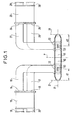
- the device of the invention comprises a main circular guide consisting of two parts 10 and 11 located in the extension of one another, and movable in rotation relative to one another around their axis of symmetry L1.
- Two accesses 12 and 13 to the first part 10 of the main guide are orthogonal thereto and orthogonal to each other. They are coupled to outputs 14 and 15 of a first hybrid coupler 18 of 3dB coupling value via two guides 16 and 17. This coupler 18 is connected at the input to two guides 19 and 20.
- These two accesses 12 and 13 are located at a distance d1 from a short-circuit plane 21 produced by a cut-off guide.
- Two accesses 22 and 23 to the second part 11 of the main guide are orthogonal thereto and orthogonal to each other. They are connected to the inputs 24 and 25 of a second hybrid coupler 26 of 3dB coupling value via two guides 27 and 28. This coupler 26 is connected at the output to two guides 29 and 30.
- These two accesses 22 and 23 are located at a distance d2 from a short-circuit plane 31 produced by a cut-off guide.
- the short-circuit plane 21 is located at a distance d1 from the two accesses 12 and 13 such that all the energy propagates in the main guide from the first part 10 to the second part 11.
- the short-circuit 31 is located at a distance d2 from the two slots 22 and 23 such that all of this energy which comes from the slots 12 and 13 propagates in the guides 27 and 28.
- the guides which make the connection between the hybrid couplers (18, 26) and the main guide (10, 11) are rectangular guides.
- One (19) of the two inputs of the hybrid coupler 18 receives a signal which is transmitted to the two guides 16 and 17 and which, by coupling with the main guide via the two ports 12 and 13, allows the transmission in that -this of a wave with circular polarization.
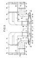
- two guides on the cut-off 35 and 36 are used on either side of the main guide (10, 11), shown in FIG. 1.
- two accesses 37 and 38 to the guide 35 are orthogonal thereto and orthogonal to each other.
- a hybrid coupler 39 connected at the input to two guides 40 and 41, has its two outputs connected to two guides 42 and 43 which are coupled to these two ports 37 and 38.
- a hybrid coupler 45 connected at the output to two guides 46 and 47, has its two inputs connected to two guides 48 and 49 which are coupled to two ports 50 and 51 of the guide 36, these two ports being orthogonal to this guide 36 and orthogonal to each other.
- the two cut-off guides 35 and 36 have their free ends 58 and 59 closed and located at a distance from the access planes (37, 38, and 50, 51) such that all the energy is transmitted from one part of the coupler 39, via ports 37 and 38, to the junction, then from the junction to coupler 45, via ports 50 and 51.
- the excitation wave of circular polarization of p princi- al guide (10, 11) is unhindered in this main guide; it follows that if four filters (54, 55 and 56, 57) of the low-pass type are placed which bring a short-circuit plane into the plane of the accesses (12, 13 and 22, 23), the device for another frequency band such that it can propagate in a diameter of the guide less than the diameter in the fictitious short-circuit planes 21 and 31 which are obtained by cut-off guides.
- the diameter of the guides 35 and 36 must therefore be less than the diameter of the guide when cut.
- the low-pass filters 54 and 55 have short-circuit planes in the planes of the accesses 12 and 13, it is therefore possible to operate with a second frequency band.
- each hybrid input coupler (18, 39) which corresponds respectively to a single output from each hybrid output coupler ( 26, 45).
- each input hybrid coupler its second input to convey a second signal at the same frequency as that conveyed by the first input.
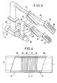
- the electrical contact between the two parts 10 and 11 of the central conductor can be made using a coupling device shown in FIG. 4.
- the electrical junction in the P plane occurs at the bottom of a corrugation.
- Such a type of junction makes it possible to obtain good electrical continuity without requiring very good mechanical contact.
- this circular polarized wave can be done using a single access 22 (or 23) after having placed a polarizing device in the second part 11 of the main guide.
Landscapes
- Waveguide Connection Structure (AREA)
- Transmission Devices (AREA)
- Variable-Direction Aerials And Aerial Arrays (AREA)
- Control Of Motors That Do Not Use Commutators (AREA)
- Waveguide Switches, Polarizers, And Phase Shifters (AREA)
Applications Claiming Priority (2)
| Application Number | Priority Date | Filing Date | Title |
|---|---|---|---|
| FR8606127A FR2598034B1 (fr) | 1986-04-28 | 1986-04-28 | Dispositif a joint tournant hyperfrequence |
| FR8606127 | 1986-04-28 |
Publications (2)
| Publication Number | Publication Date |
|---|---|
| EP0243888A1 true EP0243888A1 (de) | 1987-11-04 |
| EP0243888B1 EP0243888B1 (de) | 1991-12-18 |
Family
ID=9334687
Family Applications (1)
| Application Number | Title | Priority Date | Filing Date |
|---|---|---|---|
| EP87105976A Expired - Lifetime EP0243888B1 (de) | 1986-04-28 | 1987-04-23 | Mikrowellen-Drehkopplungsvorrichtung |
Country Status (7)
| Country | Link |
|---|---|
| US (1) | US4757281A (de) |
| EP (1) | EP0243888B1 (de) |
| CA (1) | CA1260082A (de) |
| DE (1) | DE3775261D1 (de) |
| ES (1) | ES2027988T3 (de) |
| FR (1) | FR2598034B1 (de) |
| GR (1) | GR3003863T3 (de) |
Cited By (2)
| Publication number | Priority date | Publication date | Assignee | Title |
|---|---|---|---|---|
| EP0343887A1 (de) * | 1988-05-21 | 1989-11-29 | THE GENERAL ELECTRIC COMPANY, p.l.c. | Wellenleitervorrichtung |
| EP1916015A1 (de) * | 2006-10-24 | 2008-04-30 | Pompilio Gatto | Gerät zur intraoperativen Strahlungstherapie mit Wellenleiter mit zweifacher Drehkupplung |
Families Citing this family (9)
| Publication number | Priority date | Publication date | Assignee | Title |
|---|---|---|---|---|
| US5877660A (en) * | 1994-06-02 | 1999-03-02 | Nihon Dengyo Kosaku Co., Ltd. | Phase shifting device with rotatable cylindrical case having driver means on the end walls |
| JP3908071B2 (ja) * | 2002-04-02 | 2007-04-25 | 三菱電機株式会社 | ロータリージョイント |
| KR20070068259A (ko) * | 2005-12-26 | 2007-06-29 | 히타치 기자이 가부시키가이샤 | 체인·스프로킷 기구, 체인 및 스프로킷 |
| DE202009006651U1 (de) | 2008-12-30 | 2009-07-23 | Dr. Nathrath, Trümper, Partnerschaft Ingenieure | Mirowellen-Drehkupplung für Rechteckhohlleiter |
| JP5446552B2 (ja) * | 2009-07-30 | 2014-03-19 | ソニー株式会社 | 無線通信装置、回転構造体、電子機器 |
| US9640851B2 (en) * | 2014-05-26 | 2017-05-02 | The Board Of Trustees Of The Leland Stanford Junior University | RF waveguide phase-directed power combiners |
| US10522887B2 (en) * | 2017-10-20 | 2019-12-31 | Waymo Llc | Communication system for a vehicle comprising a dual channel rotary joint coupled to a plurality of interface waveguides for coupling electromagnetic signals between plural communication chips |
| US11152675B2 (en) | 2017-10-20 | 2021-10-19 | Waymo Llc | Communication system for LIDAR sensors used in a vehicle comprising a rotary joint with a bearing waveguide for coupling signals with communication chips |
| US10742315B1 (en) | 2019-05-21 | 2020-08-11 | Waymo Llc | Automotive communication system with dielectric waveguide cable and wireless contactless rotary joint |
Citations (4)
| Publication number | Priority date | Publication date | Assignee | Title |
|---|---|---|---|---|
| US2526383A (en) * | 1948-01-23 | 1950-10-17 | Gen Electric | Wave guide mode converter |
| US3668567A (en) * | 1970-07-02 | 1972-06-06 | Hughes Aircraft Co | Dual mode rotary microwave coupler |
| EP0045682A1 (de) * | 1980-07-31 | 1982-02-10 | Thomson-Csf | Speiseanordnung für eine Sende/Empfangsantenne |
| US4412192A (en) * | 1981-08-14 | 1983-10-25 | The United States Of America As Represented By The Secretary Of The Navy | Millimeter wave dielectric waveguide rotary joint |
Family Cites Families (3)
| Publication number | Priority date | Publication date | Assignee | Title |
|---|---|---|---|---|
| FR2577719B1 (fr) * | 1985-02-15 | 1987-05-29 | Alcatel Espace | Duplexeur de polarisations |
| IT1181958B (it) * | 1985-03-27 | 1987-09-30 | Selenia Spazio Spa | Dispositivo per la combinazione senza perdite della potenza rf di due o piu' trasmettitori a microonde funzionanti in parallelo e con qualsiasi rapporto di potenza |
| EP0196065B1 (de) * | 1985-03-27 | 1990-10-31 | Siemens Aktiengesellschaft | Polaristationsweiche für Einrichtungen der Höchstfreqenztechnik |
-
1986
- 1986-04-28 FR FR8606127A patent/FR2598034B1/fr not_active Expired
-
1987
- 1987-04-22 US US07/041,253 patent/US4757281A/en not_active Expired - Fee Related
- 1987-04-23 EP EP87105976A patent/EP0243888B1/de not_active Expired - Lifetime
- 1987-04-23 DE DE8787105976T patent/DE3775261D1/de not_active Expired - Fee Related
- 1987-04-23 ES ES198787105976T patent/ES2027988T3/es not_active Expired - Lifetime
- 1987-04-28 CA CA000535846A patent/CA1260082A/fr not_active Expired
-
1992
- 1992-02-21 GR GR920400281T patent/GR3003863T3/el unknown
Patent Citations (4)
| Publication number | Priority date | Publication date | Assignee | Title |
|---|---|---|---|---|
| US2526383A (en) * | 1948-01-23 | 1950-10-17 | Gen Electric | Wave guide mode converter |
| US3668567A (en) * | 1970-07-02 | 1972-06-06 | Hughes Aircraft Co | Dual mode rotary microwave coupler |
| EP0045682A1 (de) * | 1980-07-31 | 1982-02-10 | Thomson-Csf | Speiseanordnung für eine Sende/Empfangsantenne |
| US4412192A (en) * | 1981-08-14 | 1983-10-25 | The United States Of America As Represented By The Secretary Of The Navy | Millimeter wave dielectric waveguide rotary joint |
Cited By (2)
| Publication number | Priority date | Publication date | Assignee | Title |
|---|---|---|---|---|
| EP0343887A1 (de) * | 1988-05-21 | 1989-11-29 | THE GENERAL ELECTRIC COMPANY, p.l.c. | Wellenleitervorrichtung |
| EP1916015A1 (de) * | 2006-10-24 | 2008-04-30 | Pompilio Gatto | Gerät zur intraoperativen Strahlungstherapie mit Wellenleiter mit zweifacher Drehkupplung |
Also Published As
| Publication number | Publication date |
|---|---|
| FR2598034B1 (fr) | 1988-08-26 |
| FR2598034A1 (fr) | 1987-10-30 |
| GR3003863T3 (de) | 1993-03-16 |
| DE3775261D1 (de) | 1992-01-30 |
| EP0243888B1 (de) | 1991-12-18 |
| US4757281A (en) | 1988-07-12 |
| ES2027988T3 (es) | 1992-07-01 |
| CA1260082A (fr) | 1989-09-26 |
Similar Documents
| Publication | Publication Date | Title |
|---|---|---|
| EP0314101A1 (de) | Radiofrequenzoptisches Übertragungssystem, besonders für Satellitenfunken | |
| EP0243888B1 (de) | Mikrowellen-Drehkopplungsvorrichtung | |
| EP0098192B1 (de) | Multiplexanordnung zum Zusammenfügen von zwei Frequenzbändern | |
| EP3179551B1 (de) | Kompakteinheit zur doppelpolarisierten ansteuerung für ein strahlungselement einer antenne, und kompaktes netz, das mindestens vier kompakte ansteuerungseinheiten umfasst | |
| CH615534A5 (de) | ||
| EP0074295B1 (de) | Passiver Mikrowellenduplexer mit Halbleitern | |
| WO1999060661A1 (fr) | Dispositif d'emission et de reception d'ondes hyperfrequences polarisees circulairement | |
| EP1216493A1 (de) | Leistungsverteiler in einer plasmavorrichtung | |
| EP2446504A1 (de) | Antennensystem mit ausgeglichenem positionierer | |
| EP0377155B1 (de) | Doppelfrequenz strahlende Vorrichtung | |
| EP0472483A1 (de) | Bidirektionaler Duplexer für polarisierte Mikrowellen, insbesondere realisiert in monolithischer Technologie auf Galliumarsenid | |
| EP3811458A1 (de) | Hochfrequenzerreger einer empfangs- und sendeantenne | |
| FR2779294A1 (fr) | Dispositif d'emission/reception de signaux | |
| EP0073165B1 (de) | Mikrowellenschalter | |
| EP0443484A1 (de) | Redundanzgesicherte Leistungsverbindung für Mikrowellensignale | |
| EP0192186B1 (de) | Polarisationsweiche | |
| EP3249823B1 (de) | Kompakter doppelpolarisierter funkfrequenzerreger mit mehrfachfrequenzen für antennenprimärstrahler, und mit einem solchen funkfrequenzerreger ausgestatteter antennenprimärstrahler | |
| FR2844651A1 (fr) | Dispositif d'emission destine a etre couple avec un dispositif de reception | |
| EP3955374B1 (de) | Schaltung mit zirkulatorfunktion mit siw-technologie, entsprechender sende-/empfangskanal und radar | |
| EP4386990B1 (de) | Antenne und zugehöriger koppler zur durchführung eines versatzs einer antennenfunktion sowie zugehörige kommunikationsvorrichtung | |
| EP0599679B1 (de) | Fernrückschleifsystem für Funkübertragungs-Sendeempfänger | |
| EP0957590A1 (de) | Schaltung und Verfahren für Aussendung und Empfang von Mikrowellen | |
| FR2828583A1 (fr) | Procede de fermeture d'une antenne a balayage electronique, procede de reglage et dephaseur d'une telle antenne | |
| FR2772991A1 (fr) | Antenne fixe g.s.m. | |
| FR3165531A1 (fr) | Extracteur de mode d’un signal électromagnétique |
Legal Events
| Date | Code | Title | Description |
|---|---|---|---|
| PUAI | Public reference made under article 153(3) epc to a published international application that has entered the european phase |
Free format text: ORIGINAL CODE: 0009012 |
|
| AK | Designated contracting states |
Kind code of ref document: A1 Designated state(s): BE DE ES FR GB GR IT NL SE |
|
| 17P | Request for examination filed |
Effective date: 19880504 |
|
| 17Q | First examination report despatched |
Effective date: 19900705 |
|
| GRAA | (expected) grant |
Free format text: ORIGINAL CODE: 0009210 |
|
| AK | Designated contracting states |
Kind code of ref document: B1 Designated state(s): BE DE ES FR GB GR IT NL SE |
|
| REF | Corresponds to: |
Ref document number: 3775261 Country of ref document: DE Date of ref document: 19920130 |
|
| GBT | Gb: translation of ep patent filed (gb section 77(6)(a)/1977) | ||
| ITF | It: translation for a ep patent filed | ||
| REG | Reference to a national code |
Ref country code: ES Ref legal event code: FG2A Ref document number: 2027988 Country of ref document: ES Kind code of ref document: T3 |
|
| PLBE | No opposition filed within time limit |
Free format text: ORIGINAL CODE: 0009261 |
|
| STAA | Information on the status of an ep patent application or granted ep patent |
Free format text: STATUS: NO OPPOSITION FILED WITHIN TIME LIMIT |
|
| REG | Reference to a national code |
Ref country code: GR Ref legal event code: FG4A Free format text: 3003863 |
|
| 26N | No opposition filed | ||
| PGFP | Annual fee paid to national office [announced via postgrant information from national office to epo] |
Ref country code: GR Payment date: 19921228 Year of fee payment: 7 |
|
| PGFP | Annual fee paid to national office [announced via postgrant information from national office to epo] |
Ref country code: ES Payment date: 19930121 Year of fee payment: 7 |
|
| PGFP | Annual fee paid to national office [announced via postgrant information from national office to epo] |
Ref country code: SE Payment date: 19930122 Year of fee payment: 7 |
|
| PGFP | Annual fee paid to national office [announced via postgrant information from national office to epo] |
Ref country code: BE Payment date: 19930202 Year of fee payment: 7 |
|
| PGFP | Annual fee paid to national office [announced via postgrant information from national office to epo] |
Ref country code: DE Payment date: 19930217 Year of fee payment: 7 |
|
| PGFP | Annual fee paid to national office [announced via postgrant information from national office to epo] |
Ref country code: GB Payment date: 19930225 Year of fee payment: 7 |
|
| PGFP | Annual fee paid to national office [announced via postgrant information from national office to epo] |
Ref country code: NL Payment date: 19930430 Year of fee payment: 7 |
|
| PG25 | Lapsed in a contracting state [announced via postgrant information from national office to epo] |
Ref country code: GB Effective date: 19940423 |
|
| PG25 | Lapsed in a contracting state [announced via postgrant information from national office to epo] |
Ref country code: SE Effective date: 19940424 |
|
| PG25 | Lapsed in a contracting state [announced via postgrant information from national office to epo] |
Ref country code: ES Free format text: LAPSE BECAUSE OF NON-PAYMENT OF DUE FEES Effective date: 19940425 |
|
| PG25 | Lapsed in a contracting state [announced via postgrant information from national office to epo] |
Ref country code: BE Effective date: 19940430 |
|
| BERE | Be: lapsed |
Owner name: ALCATEL ESPACE Effective date: 19940430 |
|
| PG25 | Lapsed in a contracting state [announced via postgrant information from national office to epo] |
Ref country code: GR Free format text: THE PATENT HAS BEEN ANNULLED BY A DECISION OF A NATIONAL AUTHORITY Effective date: 19941031 |
|
| PG25 | Lapsed in a contracting state [announced via postgrant information from national office to epo] |
Ref country code: NL Effective date: 19941101 |
|
| NLV4 | Nl: lapsed or anulled due to non-payment of the annual fee | ||
| GBPC | Gb: european patent ceased through non-payment of renewal fee |
Effective date: 19940423 |
|
| PGFP | Annual fee paid to national office [announced via postgrant information from national office to epo] |
Ref country code: FR Payment date: 19941230 Year of fee payment: 9 |
|
| PG25 | Lapsed in a contracting state [announced via postgrant information from national office to epo] |
Ref country code: DE Effective date: 19950103 |
|
| EUG | Se: european patent has lapsed |
Ref document number: 87105976.2 Effective date: 19941110 |
|
| REG | Reference to a national code |
Ref country code: GR Ref legal event code: MM2A Free format text: 3003863 |
|
| PG25 | Lapsed in a contracting state [announced via postgrant information from national office to epo] |
Ref country code: FR Effective date: 19961227 |
|
| REG | Reference to a national code |
Ref country code: FR Ref legal event code: ST |
|
| REG | Reference to a national code |
Ref country code: ES Ref legal event code: FD2A Effective date: 19990201 |
|
| PG25 | Lapsed in a contracting state [announced via postgrant information from national office to epo] |
Ref country code: IT Free format text: LAPSE BECAUSE OF NON-PAYMENT OF DUE FEES;WARNING: LAPSES OF ITALIAN PATENTS WITH EFFECTIVE DATE BEFORE 2007 MAY HAVE OCCURRED AT ANY TIME BEFORE 2007. THE CORRECT EFFECTIVE DATE MAY BE DIFFERENT FROM THE ONE RECORDED. Effective date: 20050423 |