EP0243980A2 - Arrangement de contacts pour disjoncteurs de puissance à basse tension limitant le courant - Google Patents
Arrangement de contacts pour disjoncteurs de puissance à basse tension limitant le courant Download PDFInfo
- Publication number
- EP0243980A2 EP0243980A2 EP87106355A EP87106355A EP0243980A2 EP 0243980 A2 EP0243980 A2 EP 0243980A2 EP 87106355 A EP87106355 A EP 87106355A EP 87106355 A EP87106355 A EP 87106355A EP 0243980 A2 EP0243980 A2 EP 0243980A2
- Authority
- EP
- European Patent Office
- Prior art keywords
- contact
- arms
- arrangement according
- pieces
- parts
- Prior art date
- Legal status (The legal status is an assumption and is not a legal conclusion. Google has not performed a legal analysis and makes no representation as to the accuracy of the status listed.)
- Granted
Links
Images
Classifications
-
- H—ELECTRICITY
- H01—ELECTRIC ELEMENTS
- H01H—ELECTRIC SWITCHES; RELAYS; SELECTORS; EMERGENCY PROTECTIVE DEVICES
- H01H77/00—Protective overload circuit-breaking switches operated by excess current and requiring separate action for resetting
- H01H77/02—Protective overload circuit-breaking switches operated by excess current and requiring separate action for resetting in which the excess current itself provides the energy for opening the contacts, and having a separate reset mechanism
- H01H77/10—Protective overload circuit-breaking switches operated by excess current and requiring separate action for resetting in which the excess current itself provides the energy for opening the contacts, and having a separate reset mechanism with electrodynamic opening
- H01H77/102—Protective overload circuit-breaking switches operated by excess current and requiring separate action for resetting in which the excess current itself provides the energy for opening the contacts, and having a separate reset mechanism with electrodynamic opening characterised by special mounting of contact arm, allowing blow-off movement
Definitions
- the invention relates to a contact arrangement according to the preamble of claim 1.
- DE-AS 1 638 154 which describes a self-switch in which at least one movable contact arm is pivoted by the other contact arm under the influence of short-circuit currents and their electro-dynamic forces.
- One end of a tension spring which can be moved via a dead center acts on the movable contact arm, while the other end is fastened to a pivotable auxiliary lever.
- the contact arm also has a pin for driving the auxiliary lever, which engages in an L-shaped recess in the auxiliary lever.
- the object of the invention is therefore to provide a contact arrangement in which the moments of inertia of the movable contact arms are reduced using technically simple means.
- the contact arrangement according to the invention has a particular advantage of a faster rise in the arc voltage and a better current limitation. This results in a lower short-circuit stress on the system parts to be protected and the switch itself, which also leads to a smaller switch volume.
- the above-mentioned proportional factor c contains the reciprocal of the mass m or the moment of inertia ⁇ .
- the springs shown are compression springs, the function of which can optionally also be carried out by appropriately arranged leaf springs or torsion springs.
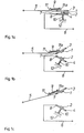
- end sections 3, 4 of pivotable contact arms 5, which may also be contact arms of bridge contacts or of c-shaped fixed contacts 6, can thus be rotated close to contact piece 1, 2 to contact arm 5 , 6 attached that the mass moments of inertia of the end sections 3, 4 are as small as possible.
- the end sections 3, 4 are supported at points 7, 8 in such a way that a rotary movement is only possible in the opening direction.
- the end sections are held in their stretched normal position by springs 9, 10, the spring forces being matched so that their force is equal to or greater than the required contact force.
- the smaller moments of inertia of the end sections 3, 4 are first accelerated and moved in the opening direction. Because of the small turning radius of the end sections 3, 4 compared to the larger radius of the pivotable contact arm 5, the end sections 3, 4 quickly form a relatively large angle to one another.
- the perpendicular to the contact areas escaping plasma jets will facilitate the formation of the base in the direction of the desired arc movement when rotated prematurely on the counter contact piece and will finally be directed into the space which lies between the end sections and an arc quenching chamber (not shown).
- the plasma rays contain almost no more neutral particles, but mainly electrons and ions, i.e. charge carriers, which prepare the arc column, as it were, the way from the contact space to the arc quenching chamber.
- the contact arm 5 has also moved clearly upwards due to the repulsive current forces in the approximately parallel current paths of the contact arm 5 and the c-shaped fixed contact 6.
- the further movement can, as with contact arrangements with rigid contact arms and rigid c-shaped fixed contacts expire.
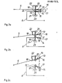
- the pivotable end sections 13, 14 with the contact pieces 1, 2 are designed as rockers, the pivot points 15 of which form the ends of the contact arm 5 and the c-shaped fixed contact 6.
- the parts 18, 19 opposite the contact-carrying parts 16, 17 of the end sections 13, 14 are insulated from one another at least up to the pivot points 15 in such a way that arcing between them is made impossible because the parts 18, 19 are still relative even after the opening movement has started stay in touch for a long time or in closer proximity.
- Springs 20, 21, which are supported on the one hand on the end sections 13, 14 and on the other hand on a spring bearing 22 of the movable contact arm 5 or on a spring bearing 23 fixed to the housing, are tuned so that the end sections 13, 14 are approximately also in the closed normal state the contact arm 5 or the upper part of the c-shaped fixed contact 6 are aligned.
- the two described arrangements accelerate relatively small moments of inertia, particularly due to the current forces, and already in the initial phase of the contact opening a relatively large angle of the contact surfaces against one another, which favors the movement of the arc base points and the ionization of the space between contact pieces and arc quenching chambers by the plasma rays.
Landscapes
- Physics & Mathematics (AREA)
- Electromagnetism (AREA)
- Breakers (AREA)
- Arc-Extinguishing Devices That Are Switches (AREA)
- Emergency Protection Circuit Devices (AREA)
Priority Applications (1)
| Application Number | Priority Date | Filing Date | Title |
|---|---|---|---|
| AT87106355T ATE78953T1 (de) | 1986-05-02 | 1987-04-30 | Kontaktanordnung fuer strombegrenzende niederspannungs-leistungsschalter. |
Applications Claiming Priority (2)
| Application Number | Priority Date | Filing Date | Title |
|---|---|---|---|
| DE3614866 | 1986-05-02 | ||
| DE19863614866 DE3614866A1 (de) | 1986-05-02 | 1986-05-02 | Kontaktanordnung fuer strombegrenzende niederspannungs-leistungsschalter |
Publications (3)
| Publication Number | Publication Date |
|---|---|
| EP0243980A2 true EP0243980A2 (fr) | 1987-11-04 |
| EP0243980A3 EP0243980A3 (en) | 1989-02-15 |
| EP0243980B1 EP0243980B1 (fr) | 1992-07-29 |
Family
ID=6300010
Family Applications (1)
| Application Number | Title | Priority Date | Filing Date |
|---|---|---|---|
| EP87106355A Expired - Lifetime EP0243980B1 (fr) | 1986-05-02 | 1987-04-30 | Arrangement de contacts pour disjoncteurs de puissance à basse tension limitant le courant |
Country Status (3)
| Country | Link |
|---|---|
| EP (1) | EP0243980B1 (fr) |
| AT (1) | ATE78953T1 (fr) |
| DE (2) | DE3614866A1 (fr) |
Family Cites Families (7)
| Publication number | Priority date | Publication date | Assignee | Title |
|---|---|---|---|---|
| NL142271B (nl) * | 1967-01-27 | 1974-05-15 | Terasaki Denki Sangyo Kk | Automatische schakelinrichting met beweegbare contactstangen openend onder invloed van elektrodynamische krachten. |
| US3534305A (en) * | 1968-11-21 | 1970-10-13 | Ite Imperial Corp | Current limiting circuit breaker |
| BE800292A (fr) * | 1973-05-30 | 1973-11-30 | Guschin Vladislav Y | Disjoncteur. |
| DE2511948C3 (de) * | 1975-03-19 | 1978-05-03 | Licentia Patent-Verwaltungs-Gmbh, 6000 Frankfurt | Strombegrenzender Leistungsschalter |
| DD154561B1 (de) * | 1980-11-17 | 1986-04-23 | Wolfgang Pump | Kontakteinrichtung für strombegrenzende Leitungsschutzschalter |
| IE56136B1 (en) * | 1983-12-19 | 1991-04-24 | Westinghouse Electric Corp | Circuit breaker with improved cross-bar and contact assembly |
| DD225237A1 (de) * | 1984-07-02 | 1985-07-24 | Zeiss Jena Veb Carl | Einrichtung zum abgleich des abbiildungsmassstabes |
-
1986
- 1986-05-02 DE DE19863614866 patent/DE3614866A1/de active Granted
-
1987
- 1987-04-30 DE DE8787106355T patent/DE3780690D1/de not_active Expired - Fee Related
- 1987-04-30 EP EP87106355A patent/EP0243980B1/fr not_active Expired - Lifetime
- 1987-04-30 AT AT87106355T patent/ATE78953T1/de not_active IP Right Cessation
Also Published As
| Publication number | Publication date |
|---|---|
| ATE78953T1 (de) | 1992-08-15 |
| EP0243980B1 (fr) | 1992-07-29 |
| DE3780690D1 (de) | 1992-09-03 |
| DE3614866A1 (de) | 1987-11-05 |
| EP0243980A3 (en) | 1989-02-15 |
| DE3614866C2 (fr) | 1989-04-06 |
Similar Documents
| Publication | Publication Date | Title |
|---|---|---|
| DE69402597T2 (de) | Mehrpoliger Strombegrenzungsschalter mit elektrodynamischer Abstossung | |
| DE19602118C2 (de) | Elektrisches Schaltgerät | |
| DE69304374T2 (de) | Schutzschalter mit Pressformgehäuse mit Verzögerung am Bewegungsende der Kontaktbrückenabstossung | |
| EP0174904A1 (fr) | Dispositif de contact pour disjoncteur basse tension avec un levier de contact à deux bras | |
| EP0006637B1 (fr) | Disjoncteur limiteur de courant multipolaire | |
| DE670790C (de) | Thermisch wirkender Selbstschalter | |
| DE2838630C2 (fr) | ||
| DE3882240T2 (de) | Selbstschalter mit magnetischem Rückhalteshuntkreis. | |
| DE1588258A1 (de) | Mit Strombegrenzung arbeitender Stromunterbrecher | |
| EP1302960B1 (fr) | Dispositif de contact pour disjoncteur limiteur de courant | |
| DE69014741T2 (de) | Betätigungsmechanismus für elektrischen Schalter. | |
| EP0772215B1 (fr) | Sectionneur, en particulier disjoncteur sectionneur pour moyenne tension | |
| EP1334503A1 (fr) | Systeme de contact pour disjoncteurs limiteurs de courant | |
| DE1938929A1 (de) | Stromunterbrecher | |
| EP0916151B1 (fr) | Disjoncteur limiteur de courant | |
| DE2935915A1 (de) | Elektrischer vakuumschalter | |
| DE10056820A1 (de) | Kontaktanordnung für strombegrenzende Schutzschalter | |
| DE69516790T2 (de) | Mittelspannungsschalter oder Schutzschalter | |
| DE102007040164A1 (de) | Schaltgerät mit einem doppelt unterbrechenden Drehkontaktsystem sowie mehrpolige Schaltgeräteanordnung | |
| EP0243980A2 (fr) | Arrangement de contacts pour disjoncteurs de puissance à basse tension limitant le courant | |
| DE10219022B3 (de) | Kontaktanordnung für strombegrenzende Schutzschalter | |
| DE19629867A1 (de) | Strombegrenzender Leistungsschalter | |
| DE2138381C3 (de) | Schutzschalter, insbesondere Leitungsschutzschalter | |
| DE2338637A1 (de) | Kontaktanordnung fuer elektrisches schaltgeraet | |
| AT400990B (de) | Lasttrennschalter |
Legal Events
| Date | Code | Title | Description |
|---|---|---|---|
| PUAI | Public reference made under article 153(3) epc to a published international application that has entered the european phase |
Free format text: ORIGINAL CODE: 0009012 |
|
| AK | Designated contracting states |
Kind code of ref document: A2 Designated state(s): AT BE CH DE FR GB IT LI SE |
|
| PUAL | Search report despatched |
Free format text: ORIGINAL CODE: 0009013 |
|
| AK | Designated contracting states |
Kind code of ref document: A3 Designated state(s): AT BE CH DE FR GB IT LI SE |
|
| 17P | Request for examination filed |
Effective date: 19890307 |
|
| 17Q | First examination report despatched |
Effective date: 19910312 |
|
| GRAA | (expected) grant |
Free format text: ORIGINAL CODE: 0009210 |
|
| AK | Designated contracting states |
Kind code of ref document: B1 Designated state(s): AT BE CH DE FR GB IT LI SE |
|
| PG25 | Lapsed in a contracting state [announced via postgrant information from national office to epo] |
Ref country code: IT Free format text: LAPSE BECAUSE OF FAILURE TO SUBMIT A TRANSLATION OF THE DESCRIPTION OR TO PAY THE FEE WITHIN THE PRE;WARNING: LAPSES OF ITALIAN PATENTS WITH EFFECTIVE DATE BEFORE 2007 MAY HAVE OCCURRED AT ANY TIME BEFORE 2007. THE CORRECT EFFECTIVE DATE MAY BE DIFFERENT FROM THE ONE RECORDED.SCRIBED TIME-LIMIT Effective date: 19920729 Ref country code: SE Effective date: 19920729 Ref country code: GB Effective date: 19920729 Ref country code: FR Effective date: 19920729 Ref country code: BE Effective date: 19920729 |
|
| REF | Corresponds to: |
Ref document number: 78953 Country of ref document: AT Date of ref document: 19920815 Kind code of ref document: T |
|
| REF | Corresponds to: |
Ref document number: 3780690 Country of ref document: DE Date of ref document: 19920903 |
|
| EN | Fr: translation not filed | ||
| GBV | Gb: ep patent (uk) treated as always having been void in accordance with gb section 77(7)/1977 [no translation filed] |
Effective date: 19920729 |
|
| PG25 | Lapsed in a contracting state [announced via postgrant information from national office to epo] |
Ref country code: AT Effective date: 19930430 Ref country code: CH Effective date: 19930430 Ref country code: LI Effective date: 19930430 |
|
| PLBE | No opposition filed within time limit |
Free format text: ORIGINAL CODE: 0009261 |
|
| STAA | Information on the status of an ep patent application or granted ep patent |
Free format text: STATUS: NO OPPOSITION FILED WITHIN TIME LIMIT |
|
| 26N | No opposition filed | ||
| REG | Reference to a national code |
Ref country code: CH Ref legal event code: PL |
|
| PGFP | Annual fee paid to national office [announced via postgrant information from national office to epo] |
Ref country code: DE Payment date: 19950412 Year of fee payment: 9 |
|
| PG25 | Lapsed in a contracting state [announced via postgrant information from national office to epo] |
Ref country code: DE Effective date: 19970101 |