EP0244191A1 - Ventilateurs - Google Patents
Ventilateurs Download PDFInfo
- Publication number
- EP0244191A1 EP0244191A1 EP87303719A EP87303719A EP0244191A1 EP 0244191 A1 EP0244191 A1 EP 0244191A1 EP 87303719 A EP87303719 A EP 87303719A EP 87303719 A EP87303719 A EP 87303719A EP 0244191 A1 EP0244191 A1 EP 0244191A1
- Authority
- EP
- European Patent Office
- Prior art keywords
- louvres
- ventilator
- louvre
- ventilation opening
- members
- Prior art date
- Legal status (The legal status is an assumption and is not a legal conclusion. Google has not performed a legal analysis and makes no representation as to the accuracy of the status listed.)
- Withdrawn
Links
- 238000009423 ventilation Methods 0.000 claims abstract description 16
- 230000015572 biosynthetic process Effects 0.000 claims description 19
- 238000005755 formation reaction Methods 0.000 claims description 19
- XLYOFNOQVPJJNP-UHFFFAOYSA-N water Substances O XLYOFNOQVPJJNP-UHFFFAOYSA-N 0.000 description 7
- 239000004677 Nylon Substances 0.000 description 5
- 230000007246 mechanism Effects 0.000 description 5
- 229920001778 nylon Polymers 0.000 description 5
- 229910052751 metal Inorganic materials 0.000 description 4
- 239000002184 metal Substances 0.000 description 4
- 239000004411 aluminium Substances 0.000 description 3
- 229910052782 aluminium Inorganic materials 0.000 description 3
- XAGFODPZIPBFFR-UHFFFAOYSA-N aluminium Chemical compound [Al] XAGFODPZIPBFFR-UHFFFAOYSA-N 0.000 description 3
- 238000010276 construction Methods 0.000 description 2
- 230000000149 penetrating effect Effects 0.000 description 2
- 238000005452 bending Methods 0.000 description 1
- 238000005253 cladding Methods 0.000 description 1
- 230000008878 coupling Effects 0.000 description 1
- 238000010168 coupling process Methods 0.000 description 1
- 238000005859 coupling reaction Methods 0.000 description 1
- 230000001419 dependent effect Effects 0.000 description 1
- 238000001125 extrusion Methods 0.000 description 1
- 230000037431 insertion Effects 0.000 description 1
- 238000003780 insertion Methods 0.000 description 1
- 239000000463 material Substances 0.000 description 1
- 239000004417 polycarbonate Substances 0.000 description 1
- 229920000515 polycarbonate Polymers 0.000 description 1
- 238000010079 rubber tapping Methods 0.000 description 1
- 238000007665 sagging Methods 0.000 description 1
- 239000000779 smoke Substances 0.000 description 1
- 230000003068 static effect Effects 0.000 description 1
- 238000003466 welding Methods 0.000 description 1
Images


Classifications
-
- E—FIXED CONSTRUCTIONS
- E04—BUILDING
- E04B—GENERAL BUILDING CONSTRUCTIONS; WALLS, e.g. PARTITIONS; ROOFS; FLOORS; CEILINGS; INSULATION OR OTHER PROTECTION OF BUILDINGS
- E04B7/00—Roofs; Roof construction with regard to insulation
- E04B7/16—Roof structures with movable roof parts
- E04B7/163—Roof structures with movable roof parts characterised by a pivoting movement of the movable roof parts
-
- A—HUMAN NECESSITIES
- A62—LIFE-SAVING; FIRE-FIGHTING
- A62C—FIRE-FIGHTING
- A62C2/00—Fire prevention or containment
- A62C2/06—Physical fire-barriers
- A62C2/12—Hinged dampers
- A62C2/14—Hinged dampers with two or more blades
-
- E—FIXED CONSTRUCTIONS
- E06—DOORS, WINDOWS, SHUTTERS, OR ROLLER BLINDS IN GENERAL; LADDERS
- E06B—FIXED OR MOVABLE CLOSURES FOR OPENINGS IN BUILDINGS, VEHICLES, FENCES OR LIKE ENCLOSURES IN GENERAL, e.g. DOORS, WINDOWS, BLINDS, GATES
- E06B7/00—Special arrangements or measures in connection with doors or windows
- E06B7/02—Special arrangements or measures in connection with doors or windows for providing ventilation, e.g. through double windows; Arrangement of ventilation roses
- E06B7/08—Louvre doors, windows or grilles
- E06B7/084—Louvre doors, windows or grilles with rotatable lamellae
- E06B7/086—Louvre doors, windows or grilles with rotatable lamellae interconnected for concurrent movement
-
- F—MECHANICAL ENGINEERING; LIGHTING; HEATING; WEAPONS; BLASTING
- F24—HEATING; RANGES; VENTILATING
- F24F—AIR-CONDITIONING; AIR-HUMIDIFICATION; VENTILATION; USE OF AIR CURRENTS FOR SCREENING
- F24F13/00—Details common to, or for air-conditioning, air-humidification, ventilation or use of air currents for screening
- F24F13/08—Air-flow control members, e.g. louvres, grilles, flaps or guide plates
- F24F13/10—Air-flow control members, e.g. louvres, grilles, flaps or guide plates movable, e.g. dampers
- F24F13/14—Air-flow control members, e.g. louvres, grilles, flaps or guide plates movable, e.g. dampers built up of tilting members, e.g. louvre
- F24F13/15—Air-flow control members, e.g. louvres, grilles, flaps or guide plates movable, e.g. dampers built up of tilting members, e.g. louvre with parallel simultaneously tiltable lamellae
-
- F—MECHANICAL ENGINEERING; LIGHTING; HEATING; WEAPONS; BLASTING
- F24—HEATING; RANGES; VENTILATING
- F24F—AIR-CONDITIONING; AIR-HUMIDIFICATION; VENTILATION; USE OF AIR CURRENTS FOR SCREENING
- F24F11/00—Control or safety arrangements
- F24F11/30—Control or safety arrangements for purposes related to the operation of the system, e.g. for safety or monitoring
- F24F11/32—Responding to malfunctions or emergencies
- F24F11/33—Responding to malfunctions or emergencies to fire, excessive heat or smoke
- F24F11/34—Responding to malfunctions or emergencies to fire, excessive heat or smoke by opening air passages
Definitions
- the present invention comprises improvements in ventilators and ccncerns controllable, louvred ventilators for natural inlet or extract ventilation, dependent upon siting, and which are suited for use as heat and smoke exhaust ventilators in the event of fire.
- One object of the present invention is to provide a controllable, louvred ventilator which is more readily manufactured in different sizes.
- a controllable, louvred ventilator having open and closed pcsitions, in which each louvre is pivotally supported at opposite ends for opening end closing mcvements between one opposite pair of side members of a frame of the ventilator defining a ventilation opening tc be controlled by the louvres and is also supported, between its ends, on a pivot arm carried from an intermediate frame member spanning the ventilation opening between a further opposite pair of side members of said ventilator frame.
- each louvre By pivotally supporting each louvre at opposite ends and between its ends, sagging or bending of the louvres is reduced.
- the span of the louvres may be selected to suit a ventilator of any required width.
- the pivot arms extend sufficiently from the intermediate frame member or members and are inclined with respect thereto such that the louvres are free tc open through an angle of substantially 90°.
- the louvres are ccnveniently controlled fcr opening and closing movements by a control member which is bodily movable and which is connected with the louvres by a series of links, there being a separate link for each louvre, each link being pivoted at its opposite ends respectively to the lccute and to the control member, the link-louvre pivots being positioned close to the pivot arm-louvre pivots in the lengthwise direction of the lcconferences.
- control member is suppcrted by, and is slidable on, said intermediate frame member or one of said intermediate frame members in order to add still further rigidity to the ventilator structure.
- the ventilator is a louvred ventilator for roof cr wall mounting.
- the ventilator has a rectangular body comprising a base 10, best seen in Fig. 2, presenting a base flange 11 for flashing the ventilator to the roof or wall W.
- the base flange 11 is flat in the present example but it may be of any of the standard shapes suitable for flashing it to different kinds of roof or wall cladding cr to glazing bars.
- the base 10 has an upstanding wall 12 defining a rectangular ventilation opening 14 through the base, the wall having a downwardly directed lip 12'. along its upper edge overhanging the base flange 11.
- the base may conveniently be formed by welding together; as at 10', four roll-formed or extruded sheet metal, e.g.
- the ventilator further comprises a readily removable outer body part 20 made up of opposite pairs of straight channel sectioned members 16, 16 and and 17, 18 removably interconnected with one another at their adjacent ends by means of self-tapping screws 21.
- the members 16, 17, 18 are formed as extruded metal, e.g. aluminium, sections and each presents an equally spaced pair of walls extending away from the base flange 11 to the outside of the wall 12.
- the wall, e.g. 18' see Fig. 3) of this pair of walls adjacent the wall 12 abuts the outside of the wall 12 and is engaged under the overhanging lip portion 12', each wall, such as 18', itself having a corresponding downturned lip along its upper edge.
- the adjacent walls, such as 18', of all the members 16, 17, 18 substantially correspond with one another in cross-sectional size and shape to interfit with the wall 12 in the manner seen in Fig. 3.
- the webs or floors 16a, 17a, 18d of the channel members 16, 17, 18 abut the base flange 11.
- the channel members 16, 17, 18 act as drainage channels for water which runs off the louvres 15.
- the other upstanding walls 16", 17" and 18" of the channel members 16, 17, l8 form a rectangular frame or box which carries the pivots for the outer ends of the lovures 15.
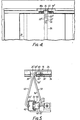
- the louvre end pivots 22 are arranged as seen in Fig. 4. These pivots, which are formed by headed pivot pins, are driven into the respective ends of part-cylindrical channels formed in hollow part-cylindrical (270°) formations 24 extending along the longitudinal louvre centre lines, and corresponding formations 26 are also provided, .extending parall-el to the central formations 24, adjacent the inwardly opening, trailing edges of the louvres, for fixing link-louvre pivots in a manner which will be described below.
- the louvres 15 are cut to the required length from metal, e.g. aluminium, extrusions of the section indicated in Fig.
- leading and trailing edge formations 28, 29 which overlap one another in the closed position of the louvres, as best shown in Fig. 3.
- the leading edge formations 28 carry elastomeric seals 30,which may be lip seals, carried by the formations 28 which seals then act to resist water penetrating under the leading edges of the louvres, and water penetrating under the leading edges of the louvres is trapped in the trailing edge rain channels 32 which also act to catch and drain off water into the channel members 16 of the body part 20, particularly when the louvres are in a partly opened position and the ventilator is flat roof mounted.
- the louvre end pivots 22 are provided with bearing shoulders 34 which bear directly in the walls 16" of the box and the pivot pins 22 are secured in the formations 24 by wing formations 22 1 on the pins which occupy cross-cuts 36 in the formations-24, formed prior to assembly of the ventilator, the pins 'being driven into the formations 24 until the wings 22' reach this position whereby the louvres 15 are predeterminedly positioned between the walls 16".
- the pins have splines 22" which fit closely between the free edges of the channel formation 24 of the louvre.
- the gaps between the louvre ends and the walls 16" are sealed with pile weather seals 38a, 38b mounted in open-ended T-slots formed on the insides of the walls 16" and form gaps 37 at the ends of the channels 32 for the drainage of water from these channels when the louvres are in a closed position.
- Each louvre 15 is also supported, between its ends, on a wire pivot arm 40 carried from an intermediate frame member 42 which spans the ventilation. opening 14 between the opposite pair of its side walls 12 extending in the longitudinal direction of the louvres.
- the member 42 is metal, e.g. aliminium hollow extruded section and is attached to the walls 12 by means of brackets 44 welded or rivetted to the walls during assembly of the ventilator.
- the member 42 is centrally disposed between the walls 16" and carries a control member 46 supported by, and slidable on, the member 42 by means of ball bearing slides 48, the balls of which are trapped in cages 50 and move between runways 52, 54 of the members 42 and 46 respectively to provide a low friction, linear slider mechanism for opening and closing the louvres.
- the bodily movable control member 46 is connected with the louvres 15 by a series of wire links 56, there being a separate link 56 for each louvre. As seen in Fig.
- the link-louvre pivots 56 1 and the pivot arm-louvre pivots 40 1 are correspondingly positioned in the lengthwise direction of the louvres whereby the opening and closing forces imparted to the louvres are carried mainly or wholly by the pivot arms 40 and the intermediate frame member 42, and the louvres are substantially relieved of opening and closing forces tending to flex the louvres.
- the pivot arm-louvre pivots 40 1 and the link-louvre pivots 56 1 have Nylon (Registered-Trade Mark) pivot bearings 60 of the same general form as the pivot pins 22 fitted in the part-cylindrical channels of the louvre formations 24 and 26 respectively.
- the formations 24 and 26 are, in this case, both cut away locally, centrally of the louvres, to provide formation gaps 24 1 and 26 1 to expose part-cylindrical channel ends for insertion of the bearings 60 and the wire ends of the pivot arms and links, and to one side of the gaps 24' and 26' by cross cuts 36' corresponding to the cross cuts 36 already described for receiving the wing formations 60' of the bearings 60 corresponding to the wing formations 22 1 .
- the formation gaps 24 1 , 26 1 also provide operating spaces for the louvres to pivot on the pivots 40 1 and for the links 56 to pivot the louvres on their pivots.
- the link-control member pivots 56" also have Nylon pivot bearings 62.
- the pivot arm-frame member bushings 64 are likewise composed of Nylon but no pivoting is accommodated for in this case since, as will be understood, the pivot arms 40 remain static, the pivot arms 40 simply lending strut-like support to the louvres 15 between their ends.
- the Nylon pivot bearings 62 and the Nylon bushings 64 have wing formations to retain them in position.
- the pivot arms 40 extend sufficiently from the member 42, and are inclined with respect thereto, such that the louvres are free to . open through an angle of substantially 90° and so as to assume a vertical position when the ventilator is set horizontally, as shown in Fig. 3. In this position a maximum unobstructed throat opening for the ventilator is achieved. Also, the inclination of the pivot arms ensures that the pivot arms still lend strut-like support to the louvres even when the louvres are in their fully open position.
- the wire links 56 are of Z-shape as seen in Fig. 5 to minimize the closing forces tending to wrench the link-louvre pivots 56' and pivot bearings 60 out of the channel formations 26.
- the control member 46 may be operated in any desired fashion.
- a single acting pneumatic ram 70 is provided, carried from the frame of the ventilator, for moving the member 46 in one direction to the right in Figs. 1 to 3 to close the louvres against the action of a return spring 72 connected between the member 46 and the frame.
- the piston rod 74 of the ram is connected with the member 46 through a coupling 76 incorporating a fusible link 78, 80 so that in the event of a fire and yielding of the fusible link, the control member 46 is released for return movement, to the left in Fig. 3, by the spring 72 and the louvres are opened automatically to ventilate the fire,
- the lovures 15 and the top and bottom outer body members 17, 18 may be selected to be of increasing length to interfit with wider bases 10 to form ventilators in a range of sizes as desired.
- the members 16, 17, 18 forming the body part 20 or box are offered up separately to the base 10, when constructing the ventilator and rotated into position with their walls such as 18' engaging with their downturned upper edge lips under the lip 12'.
- the fixing screws 21 are then inserted to unite the box and fix the box to the base.
- the base 10 is then fitted with as many of the intermediate frame members 42, already mounting their brackets 44 and control mechanisms, as are required to support and operate louvres 15 spanning the width of the base. Initially, the frame members are loosely positioned.
- the louvres are assembled into the box formed by the outer body part 20 and interconnected with the control mechanisms without mechanical fixings, the various parts being simply pressed in place.
- the brackets 44 are then rivetted or welded to the base frames. Rapid assembly of ventilators as described with reference to the accompanying drawings is, therefore, achieved.
- each channel member 16 may open through the wall 18" to drain off water from the channels outside the body of the ventilator.
- the base 10 is welded in one piece and is nowhere penetrated by fixing holes. Provided, therefore, that the flange 11 is properly flashed to the roof or wall W, water cannot penetrate under or through the base. At the same time, the body part 20 of the ventilator which is exposed outside the roof or wall is readily removable, by removing the screws 21, to gain access to the louvre operating mechanism of the ventilator, e.g. for servicing.
- the louvre blades may be formed e.g. extruded from translucent material e.g. u.p.v.c. or polycarbonate. Other translucent louvre blade constructions e.g. framed constructions may be used.
Landscapes
- Engineering & Computer Science (AREA)
- Architecture (AREA)
- Structural Engineering (AREA)
- Civil Engineering (AREA)
- General Engineering & Computer Science (AREA)
- Physics & Mathematics (AREA)
- Chemical & Material Sciences (AREA)
- Electromagnetism (AREA)
- Mechanical Engineering (AREA)
- Combustion & Propulsion (AREA)
- Health & Medical Sciences (AREA)
- Public Health (AREA)
- Business, Economics & Management (AREA)
- Emergency Management (AREA)
- Air-Flow Control Members (AREA)
- Specific Sealing Or Ventilating Devices For Doors And Windows (AREA)
Applications Claiming Priority (2)
| Application Number | Priority Date | Filing Date | Title |
|---|---|---|---|
| GB8610445 | 1986-04-29 | ||
| GB08610445A GB2194325A (en) | 1986-04-29 | 1986-04-29 | Ventilators |
Publications (1)
| Publication Number | Publication Date |
|---|---|
| EP0244191A1 true EP0244191A1 (fr) | 1987-11-04 |
Family
ID=10597031
Family Applications (1)
| Application Number | Title | Priority Date | Filing Date |
|---|---|---|---|
| EP87303719A Withdrawn EP0244191A1 (fr) | 1986-04-29 | 1987-04-28 | Ventilateurs |
Country Status (4)
| Country | Link |
|---|---|
| EP (1) | EP0244191A1 (fr) |
| AU (1) | AU7188287A (fr) |
| GB (1) | GB2194325A (fr) |
| ZA (1) | ZA872965B (fr) |
Cited By (6)
| Publication number | Priority date | Publication date | Assignee | Title |
|---|---|---|---|---|
| EP0324256A3 (en) * | 1988-01-09 | 1990-07-04 | Colt International Holdings A.G. | Improvements in ventilators |
| WO1995012738A1 (fr) * | 1993-11-04 | 1995-05-11 | H.V. Aluminium Pty. Limited | Ensemble a lamelles de stores |
| WO1996006258A1 (fr) * | 1994-08-19 | 1996-02-29 | Paul Schlossbauer | Surface de mur ou de toit formee de panneaux |
| US5732507A (en) * | 1993-11-04 | 1998-03-31 | H.V. Aluminium Pty. Limited | Louvre assembly |
| WO2014128431A1 (fr) * | 2013-02-20 | 2014-08-28 | Orangebox Limited | Panneau de plafond |
| EP3929375A1 (fr) * | 2020-06-09 | 2021-12-29 | Yotrio Group Co., Ltd. | Structure de transmission stable pour auvent à persiennes longues |
Citations (5)
| Publication number | Priority date | Publication date | Assignee | Title |
|---|---|---|---|---|
| GB639857A (en) * | 1941-08-11 | 1950-07-05 | F C Russell Company | Improvements relating to closures for building apertures |
| GB1080561A (en) * | 1964-01-23 | 1967-08-23 | Nat Res Dev | Improvements in or relating to window blinds |
| FR2452678A1 (fr) * | 1979-03-29 | 1980-10-24 | Colt Int Holdings | Dispositif d'etancheite pour aerateur a persiennes |
| FR2536111A1 (fr) * | 1982-11-17 | 1984-05-18 | Bos Andre | Dispositif de fermeture a lames orientables |
| FR2557915A1 (fr) * | 1984-01-06 | 1985-07-12 | Technal International Sa | Volet perfectionne destine a faire office de persienne a lames orientables |
Family Cites Families (6)
| Publication number | Priority date | Publication date | Assignee | Title |
|---|---|---|---|---|
| GB799230A (en) * | 1955-07-06 | 1958-08-06 | Colt Ventilation Ltd | Improvements in or relating to ventilators |
| US3366032A (en) * | 1966-10-24 | 1968-01-30 | Honeywell Inc | Damper apparatus including inflatable sealing member |
| US3500739A (en) * | 1968-05-23 | 1970-03-17 | John P Dry | Plastic register with shutter blades |
| US3503321A (en) * | 1968-06-17 | 1970-03-31 | Ind Plastics Corp | Louver assembly |
| US3967779A (en) * | 1974-02-01 | 1976-07-06 | Aeronca, Inc. | Air mixing valve having a thermal motor actuator for effecting adjustment |
| US4043258A (en) * | 1976-08-19 | 1977-08-23 | International Harvester Company | Louver linkage seal |
-
1986
- 1986-04-29 GB GB08610445A patent/GB2194325A/en not_active Withdrawn
-
1987
- 1987-04-23 AU AU71882/87A patent/AU7188287A/en not_active Abandoned
- 1987-04-27 ZA ZA872965A patent/ZA872965B/xx unknown
- 1987-04-28 EP EP87303719A patent/EP0244191A1/fr not_active Withdrawn
Patent Citations (5)
| Publication number | Priority date | Publication date | Assignee | Title |
|---|---|---|---|---|
| GB639857A (en) * | 1941-08-11 | 1950-07-05 | F C Russell Company | Improvements relating to closures for building apertures |
| GB1080561A (en) * | 1964-01-23 | 1967-08-23 | Nat Res Dev | Improvements in or relating to window blinds |
| FR2452678A1 (fr) * | 1979-03-29 | 1980-10-24 | Colt Int Holdings | Dispositif d'etancheite pour aerateur a persiennes |
| FR2536111A1 (fr) * | 1982-11-17 | 1984-05-18 | Bos Andre | Dispositif de fermeture a lames orientables |
| FR2557915A1 (fr) * | 1984-01-06 | 1985-07-12 | Technal International Sa | Volet perfectionne destine a faire office de persienne a lames orientables |
Cited By (12)
| Publication number | Priority date | Publication date | Assignee | Title |
|---|---|---|---|---|
| EP0324256A3 (en) * | 1988-01-09 | 1990-07-04 | Colt International Holdings A.G. | Improvements in ventilators |
| WO1995012738A1 (fr) * | 1993-11-04 | 1995-05-11 | H.V. Aluminium Pty. Limited | Ensemble a lamelles de stores |
| US5732507A (en) * | 1993-11-04 | 1998-03-31 | H.V. Aluminium Pty. Limited | Louvre assembly |
| WO1996006258A1 (fr) * | 1994-08-19 | 1996-02-29 | Paul Schlossbauer | Surface de mur ou de toit formee de panneaux |
| WO2014128431A1 (fr) * | 2013-02-20 | 2014-08-28 | Orangebox Limited | Panneau de plafond |
| GB2526480A (en) * | 2013-02-20 | 2015-11-25 | Orangebox Ltd | A ceiling panel |
| GB2511053B (en) * | 2013-02-20 | 2017-09-20 | Orangebox Ltd | A ceiling panel |
| US9903114B2 (en) | 2013-02-20 | 2018-02-27 | Orangebox Limited | Ceiling panel |
| GB2526480B (en) * | 2013-02-20 | 2020-04-29 | Orangebox Ltd | A ceiling panel |
| US11008754B2 (en) | 2013-02-20 | 2021-05-18 | Orangebox Limited | Ceiling panel |
| US12209412B2 (en) | 2013-02-20 | 2025-01-28 | Orangebox Limited | Ceiling panel |
| EP3929375A1 (fr) * | 2020-06-09 | 2021-12-29 | Yotrio Group Co., Ltd. | Structure de transmission stable pour auvent à persiennes longues |
Also Published As
| Publication number | Publication date |
|---|---|
| AU7188287A (en) | 1987-11-05 |
| ZA872965B (en) | 1987-10-20 |
| GB2194325A (en) | 1988-03-02 |
| GB8610445D0 (en) | 1986-06-04 |
Similar Documents
| Publication | Publication Date | Title |
|---|---|---|
| KR920008689Y1 (ko) | 조절식 미늘창을 갖춘 문짝 | |
| CA1176466A (fr) | Serre chaude a armature speciale d'aeration | |
| US20200354961A1 (en) | Pergola louver tilt system | |
| US20170097171A1 (en) | Airfoil damper | |
| EP0244191A1 (fr) | Ventilateurs | |
| US3982355A (en) | Adjustable blind structure | |
| CA2002780C (fr) | Lanterneau a compartiments multiples pour grandes pieces | |
| WO1993025779A9 (fr) | Faite ventile d'un toit a pentes vitrees | |
| WO1993025779A1 (fr) | Faite ventile d'un toit a pentes vitrees | |
| US3299798A (en) | Air operated fresh air ventilator | |
| EP1870555B1 (fr) | Exutoire de fumée | |
| EP0514960B1 (fr) | Aérateur avec clapet de régulation pivotant | |
| US5179802A (en) | Louvre structures | |
| KR100379186B1 (ko) | 온실의 환기시스템 | |
| JP4297569B2 (ja) | 建物用換気装置 | |
| US2134143A (en) | Ventilator | |
| US1996340A (en) | Louver construction | |
| IE41430B1 (en) | Ventilators | |
| US3500583A (en) | Louvered building structures | |
| EP0304753A1 (fr) | Installation de ventilation | |
| US4073224A (en) | Ventilators | |
| US2998765A (en) | Pivotal louver assembly | |
| EP0436239B1 (fr) | Système de ventilation | |
| KR0119877Y1 (ko) | 건물의 환기구용 셔터 | |
| US4607567A (en) | Greenhouse construction provided with special ridge for ventilation |
Legal Events
| Date | Code | Title | Description |
|---|---|---|---|
| PUAI | Public reference made under article 153(3) epc to a published international application that has entered the european phase |
Free format text: ORIGINAL CODE: 0009012 |
|
| AK | Designated contracting states |
Kind code of ref document: A1 Designated state(s): AT BE CH DE FR LI LU NL |
|
| 17P | Request for examination filed |
Effective date: 19871110 |
|
| 17Q | First examination report despatched |
Effective date: 19881014 |
|
| STAA | Information on the status of an ep patent application or granted ep patent |
Free format text: STATUS: THE APPLICATION IS DEEMED TO BE WITHDRAWN |
|
| 18D | Application deemed to be withdrawn |
Effective date: 19890215 |
|
| RIN1 | Information on inventor provided before grant (corrected) |
Inventor name: WHEELER, JOHN |