EP0244213B1 - Construction pour stade - Google Patents
Construction pour stade Download PDFInfo
- Publication number
- EP0244213B1 EP0244213B1 EP87303783A EP87303783A EP0244213B1 EP 0244213 B1 EP0244213 B1 EP 0244213B1 EP 87303783 A EP87303783 A EP 87303783A EP 87303783 A EP87303783 A EP 87303783A EP 0244213 B1 EP0244213 B1 EP 0244213B1
- Authority
- EP
- European Patent Office
- Prior art keywords
- building according
- end segment
- stadium
- trucks
- stadium building
- Prior art date
- Legal status (The legal status is an assumption and is not a legal conclusion. Google has not performed a legal analysis and makes no representation as to the accuracy of the status listed.)
- Expired
Links
Images







Classifications
-
- E—FIXED CONSTRUCTIONS
- E04—BUILDING
- E04H—BUILDINGS OR LIKE STRUCTURES FOR PARTICULAR PURPOSES; SWIMMING OR SPLASH BATHS OR POOLS; MASTS; FENCING; TENTS OR CANOPIES, IN GENERAL
- E04H3/00—Buildings or groups of buildings for public or similar purposes; Institutions, e.g. infirmaries or prisons
- E04H3/10—Buildings or groups of buildings for public or similar purposes; Institutions, e.g. infirmaries or prisons for meetings, entertainments, or sports
- E04H3/14—Gymnasiums; Other sporting buildings
-
- E—FIXED CONSTRUCTIONS
- E04—BUILDING
- E04B—GENERAL BUILDING CONSTRUCTIONS; WALLS, e.g. PARTITIONS; ROOFS; FLOORS; CEILINGS; INSULATION OR OTHER PROTECTION OF BUILDINGS
- E04B1/00—Constructions in general; Structures which are not restricted either to walls, e.g. partitions, or floors or ceilings or roofs
- E04B1/343—Structures characterised by movable, separable, or collapsible parts, e.g. for transport
- E04B1/34305—Structures characterised by movable, separable, or collapsible parts, e.g. for transport telescopic
-
- E—FIXED CONSTRUCTIONS
- E04—BUILDING
- E04B—GENERAL BUILDING CONSTRUCTIONS; WALLS, e.g. PARTITIONS; ROOFS; FLOORS; CEILINGS; INSULATION OR OTHER PROTECTION OF BUILDINGS
- E04B7/00—Roofs; Roof construction with regard to insulation
- E04B7/16—Roof structures with movable roof parts
- E04B7/163—Roof structures with movable roof parts characterised by a pivoting movement of the movable roof parts
-
- E—FIXED CONSTRUCTIONS
- E04—BUILDING
- E04B—GENERAL BUILDING CONSTRUCTIONS; WALLS, e.g. PARTITIONS; ROOFS; FLOORS; CEILINGS; INSULATION OR OTHER PROTECTION OF BUILDINGS
- E04B7/00—Roofs; Roof construction with regard to insulation
- E04B7/16—Roof structures with movable roof parts
- E04B7/166—Roof structures with movable roof parts characterised by a translation movement of the movable roof part, with or without additional movements
Definitions
- This invention relates to a stadium building having a retractable roof or dome.
- a stadium building characterised by a retractable roof comprising a central arch separating a pair of end segments, one end segment being movable into nesting relationship with the other end segment, and the central arch being movable to rest above the nesting end segments.
- the end segments are ungular end segments.
- said other end segment is fixed.
- nesting end segments and the above nesting central arch are movable laterally, whereby the interior of the stadium is more fully exposed.
- a stadium building a retractable roof comprising a central arch separating a pair of ungular end segments, one end segment being fixed, the other end segment being movable into nesting relationship with the fixed end segment, and the central arch being movable to nest above the fixed end segment.
- a retractable roof comprising a central arch separating a pair of ungular end segments, one end segment being movable into nesting relationship with the other end segment, and the central arch being movable to rest above the nesting end segments, the nesting end segments and the above resting central arch being movable laterally whereby the interior of the stadium is more fully exposed.
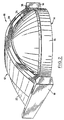
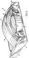
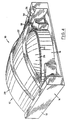
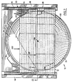
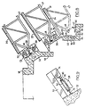
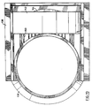
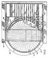
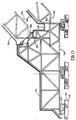
- FIG. 1 to 14 of the drawings consists of a stadium building 10 having a dome 12 resting on a wall structure 14 comprising a circular wall 16 and a pair of parallel, opposed side walls 18 which are tangential to circular wall 16.
- Dome 12 consists of a central arch comprising a pair of parallel movable barrel vaults 20 and 22 movably mounted on side walls 18, and a pair of opposed ungular end segments 24 and 26 carried by circular wall 16. End segment 24 is movably mounted on the circular wall 16.
- Each end of barrel vault 20 is carried on a row of trucks 28 which travel on a set of tracks 30 fixed on opposed parallel shoulders 32 on side walls 18.
- Each end of barrel vault 22 is carried on a row of trucks 34 which travel on a set of tracks 36 fixed on parallel shoulders 38 of side walls 18.
- End segment 24 is carried on a row of trucks 40 which travel on a set of tracks 42 in a recess 44 in circular wall 16.
- Each truck 28, 34 and 40 is joined by a pin connection 46 to a truss 47 its respective vault or segment.
- Truck 40 is shown in detail in Figure 10 of the drawings and consists of a carriage frame 48 having a set of fixed anchor plates 50 to which end segment 24 is pin connected. Two spaced pairs of double flanged wheels 52 and 54 are journally mounted in parallel on frame 48 and two further spaced pairs of double flanged wheels 56 and 58 are journally mounted in parallel on frame 48 normal to wheels 52 and 54.
- One end of frame 48 carries a coupling pin 60 and the other end carries an apertured coupling flange 62 for connecting a row of trucks 40 together.
- Certain of trucks 40 carry a pair of drive motors 64 each mounted on a gear box 66 which includes a pinion 68 engageable with a rack 70.
- Trucks 28 and 34 are of the same construction as truck 40 except that wheels 56 and 58 are removed as redundant.
- each shoulder 32 of side walls 18 carries a pair of parallel, spaced supports 72 with inturned blocks 74.
- a first pair of rails 76 are fixed on shoulder 32 and a second pair of rails 78 are fixed on blocks 74, to form track 30.
- Rack 70 is fixed on shoulder 32 between rails 76. Rails 76 and 78 are engaged by pairs of wheels 52 and 54 on truck 28 and rack 70 is engaged by pinions 68.
- the same arrangement is associated with each shoulder 38 of side walls 18, i.e. supports 72, blocks 74, rails 76 and 78 (to form tracks 32), and rack 70.
- Recess 44 in circular walls 16 has a pair of secondary recesses 80 and 82 which have fixed pairs of opposed rails 84 and 86 respectively. Recess 44 also has further rails 88 and 90 normal one to the other. Rails 84, 86, 88 and 90 together form track 42.
- Figures 11 and 12 show the arrangement of trucks 28 associated with barrel vault 20. Not every truck 28 is needed to move vault 20 and the drive trucks are sequentially spaced between slave trucks 28 a which are of the same construction as the drive trucks but do not carry motors 64.
- dome 12 when open has end segment 24, vault 20, and vault 22 stacked above fixed end segment 26 in nesting position.
- end segment 24 and vaults 20, 22 are moved as seen in Figure 7. More particularly, end segment 24 is rotated on track 42 in the direction of arrow 116 about any imaginary centre of rotation 118, vault 20 is moved linearly on track 36 in the direction of arrow 120, and vault 22 is moved linearly on track 32 in the direction of arrow 122.
- vaults 20, 22 and end segments 24, 26 carry interengaging means to seal dome 12 in its closed position.
- end segment 24 carries at its upper edge 92 an upwardly extending flange 94 which cooperates with a downwardly extending flange 96 on leading edge 98 of vault 20 to form a vertical seal with a suitable sealing element 100.
- trailing edges 102 of vault 22 carries a downwardly extending flange 104 which cooperates with upper edge 106 of end segment 26 to close the gap between the vault and the segment together with a sealing element 108.
- a sealing element 110 between trailing edge 112 of vault 20 and leading edge 114 of vault 22 completes the sealing of dome 12.
- FIG. 15 to 26 of the drawings consists of a stadium building 130 having a roof or dome 132 resting on a wall structure 134 comprising a circular wall 136, a pair of parallel opposed side walls 138 which are tangential to circular wall 136, and a platform 140 extending rearwardly of the circular wall between the side walls.
- Dome 132 consists of a central arch, comprising a barrel vault 142 which is preferably externally convex in lateral cross-section, and a pair of opposed ungular end segments 144 and 146.
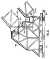
- Barrel vault 142 is mounted movably on side walls 138, end segment 144 is mounted movably on circular wall 136, and end segment 146 is mounted on a carriage 148 which is movable on a plurality of parallel rails 150 resting on platform 140.
- each end of barrel vault 142 is carried on a row of trucks 152 which travel on a set of tracks 154 fixed on opposed shoulders 156 on side walls 138, each truck being pin connected to the end of a truss of barrel vault 142.
- End segment 144 is carried on a row of trucks 158 which travel on sets of tracks 160 fixed on carriage 148, each truck being pin connected to the end of a truss of the end segment.
- the ends of the trusses of end segment 146 are connected by pins 162 to carriage 148 which is carried on rows of trucks 164 travelling on rails 150.
- Each truck 158 is independently driven by motor means (not shown) while each truck 164 is driven by a rack and pinion combination 166 in the same manner as trucks 28 in the previous embodiment.
- Carriage 148 includes additional trucks 168 which bear laterally against subsidiary rails 170 fixed on side walls 138 of building 130.
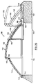
- a sheet cover 172 is mounted on carriage 148 and meets with a cover 174 on segment 144, segment 146 also having a cover 176 which includes a gutter 178.
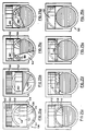
- dome 132 The manner of opening and closing dome 132 is shown in Figures 25 and 26 of the drawings. From a closed position of dome 132 as seen in Figure 25a and 26, end segment 144 is rotated on trucks 158 in the direction of arrow 180 as seen in Figures 25b, 25c and 25d until it comes to rest in a nesting position above segment 146 as seen in Figures 25e and Figure 26. At the same time barrel vault 142 is moved rearwardly on trucks 152 in the direction of arrow 182 as seen in Figures 25b, 25c and 25d until it comes to rest as seen in Figure 25e and Figure 26.
- Carriage 148 is constructed with trusses to distribute the loads of end segments 144 and 146, a portion of the loads being transferred to side walls 138 by lateral trucks 168. As in the previous embodiment, seals are provided between barrel vault 142 and end segments 144, 146 when dome 12 is in a closed position. Trucks 164 of carriage 148 are driven by rack and pinion to control uniform movement of the truck array.
- barrel vault 142 and end segments 144 and 146 carry interengaging means to seal dome 132 in its closed position.
- end segment 144 carries at its upper edge an upwardly extending flange 190 which cooperates with a downwardly extending flange 192 on the leading edge of vault 142 to form a seal and the trailing edge of the vault carries a seal 194 which interengages with end segment 146.
Landscapes
- Engineering & Computer Science (AREA)
- Architecture (AREA)
- Civil Engineering (AREA)
- Structural Engineering (AREA)
- Physics & Mathematics (AREA)
- Electromagnetism (AREA)
- Conveying And Assembling Of Building Elements In Situ (AREA)
- Excavating Of Shafts Or Tunnels (AREA)
Claims (21)
Applications Claiming Priority (4)
| Application Number | Priority Date | Filing Date | Title |
|---|---|---|---|
| US06/857,971 US4676033A (en) | 1986-05-01 | 1986-05-01 | Stadium building |
| US857971 | 1986-05-01 | ||
| US07/017,601 US4716691A (en) | 1986-05-01 | 1987-02-24 | Stadium building |
| US17601 | 1987-02-24 |
Publications (3)
| Publication Number | Publication Date |
|---|---|
| EP0244213A2 EP0244213A2 (fr) | 1987-11-04 |
| EP0244213A3 EP0244213A3 (en) | 1989-01-04 |
| EP0244213B1 true EP0244213B1 (fr) | 1992-03-04 |
Family
ID=26690089
Family Applications (1)
| Application Number | Title | Priority Date | Filing Date |
|---|---|---|---|
| EP87303783A Expired EP0244213B1 (fr) | 1986-05-01 | 1987-04-29 | Construction pour stade |
Country Status (3)
| Country | Link |
|---|---|
| US (1) | US4716691A (fr) |
| EP (1) | EP0244213B1 (fr) |
| DE (1) | DE3776955D1 (fr) |
Families Citing this family (39)
| Publication number | Priority date | Publication date | Assignee | Title |
|---|---|---|---|---|
| JPH0224428A (ja) * | 1988-07-12 | 1990-01-26 | Tobishima Corp | 可動屋根付き建築構造物 |
| JPH0224427A (ja) * | 1988-07-12 | 1990-01-26 | Tobishima Corp | 可動屋根付き建築構造物 |
| JPH02186029A (ja) * | 1989-01-11 | 1990-07-20 | Tobishima Corp | 開閉屋根付きドーム |
| JPH02186028A (ja) * | 1989-01-11 | 1990-07-20 | Tobishima Corp | 開閉屋根付き建築構造物 |
| CA2045544C (fr) * | 1989-01-25 | 1999-11-30 | William D. Goryl | Dome retractable et methode d'utilisation |
| US5257481A (en) * | 1989-01-25 | 1993-11-02 | George S. Reppas | Retractable dome |
| US5167097A (en) * | 1989-01-31 | 1992-12-01 | Robbie Roderick G | Retractable stadium roof |
| CA2013359C (fr) * | 1989-03-30 | 1993-06-08 | Hiroki Muramoto | Construction hors-toit |
| US5063730A (en) * | 1989-03-30 | 1991-11-12 | Mitsubishi Jukogyo Kabushiki Kaisha | Openable roof apparatus |
| AU615384B2 (en) * | 1989-04-10 | 1991-09-26 | Ohbayashi Corporation | Openable dome-shaped roof structure |
| JPH0347303U (fr) * | 1989-09-07 | 1991-05-01 | ||
| US5070659A (en) * | 1990-02-02 | 1991-12-10 | Stadium Consultants International, Inc. | Retractable roof for stadium structure |
| US5355641A (en) * | 1990-11-02 | 1994-10-18 | Weidlinger Associates, Inc. | Triangulated cable dome with retractable roof |
| US5440840A (en) * | 1990-11-02 | 1995-08-15 | Weidlinger Associates, Inc. | Triangulated roof structure |
| JP2885947B2 (ja) * | 1991-02-22 | 1999-04-26 | 前田建設工業株式会社 | 開閉式屋根構造 |
| JP3231072B2 (ja) * | 1992-04-08 | 2001-11-19 | 川口 衛 | ドーム式屋根構造 |
| GB9212281D0 (en) * | 1992-06-10 | 1992-07-22 | Stadium Consultants Internatio | Auditorium |
| US5857294A (en) * | 1994-08-05 | 1999-01-12 | Castro; Gerardo | Dome roof structure and method of designing and constructing same |
| US5653066A (en) * | 1995-10-17 | 1997-08-05 | Schildge, Jr.; Adam T. | Cable-stay retractable skylight roof for stadium or arena or other structure and method of construction of same |
| US5904003A (en) * | 1998-04-09 | 1999-05-18 | Stephen; John W. | Retractable stadium cover |
| US6082054A (en) * | 1998-08-27 | 2000-07-04 | Silberman; Cyril J. | Retractable stadium roofs and transport mechanism therefor |
| US6360492B1 (en) * | 2000-06-15 | 2002-03-26 | James M. Ross | Portable shade shelter for small aircraft |
| US6415556B1 (en) | 2000-07-03 | 2002-07-09 | Uni-Systems, Inc. | Transport mechanism for large structures such as retractable stadium rooves |
| US6698141B2 (en) | 2001-01-23 | 2004-03-02 | Uni-Systems, Llc | Convertible stadium and method of operating |
| US6789360B2 (en) | 2001-01-23 | 2004-09-14 | Uni-Systems, Llc | Retractable roof system for stadium |
| US6718696B2 (en) * | 2001-01-23 | 2004-04-13 | Uni-Systems, Llc | Movable wall for stadium |
| US7520091B2 (en) * | 2004-07-09 | 2009-04-21 | Friedman Daniel B | Adaptable roof system |
| US8186107B2 (en) * | 2005-03-09 | 2012-05-29 | Uni-Systems, Llc | Cable drive and control system for movable stadium roof panels |
| US7594360B2 (en) * | 2005-03-09 | 2009-09-29 | Uni-Systems, Llc | Lateral release mechanism for movable roof panels |
| WO2011088113A1 (fr) * | 2010-01-12 | 2011-07-21 | Cabreeco Companies Llc | Enceinte mobile |
| US20110308173A1 (en) * | 2009-09-04 | 2011-12-22 | Forsland Kent H | Movable building structure |
| WO2012073060A1 (fr) * | 2010-11-29 | 2012-06-07 | Qatar Football Association | Systèmes et procédés pour réguler un volume intérieur d'un stade intérieur/extérieur |
| US8387315B2 (en) * | 2010-11-29 | 2013-03-05 | Qatar Football Association | Microclimate cooling system for an indoor/outdoor stadium |
| US8555557B2 (en) * | 2010-11-29 | 2013-10-15 | Qatar Football Association | Indoor/outdoor stadium system for energy use reduction |
| US8215066B2 (en) * | 2010-11-29 | 2012-07-10 | Qatar Football Association | Multi-layer, revolving stadium roof |
| US8336261B2 (en) * | 2010-11-29 | 2012-12-25 | Qatar Football Association | Revolving roof for an indoor/outdoor stadium |
| USD796057S1 (en) * | 2012-08-03 | 2017-08-29 | Inter+-Pol Freie Forschungs- Und Entwicklungsgesellschaft Für Unfassbare Formate, Experimentelle Projekte, Ungesehene Filme, Dicke Und Dünne Bücher, Grenzenlose Räume, Angewandte Streitkultur Und Ideen Aus Ferner Zukunft Mbh | Grandstand |
| US10000926B1 (en) * | 2016-11-22 | 2018-06-19 | Jesus Morfin | Retractable roof system |
| IT201700036862A1 (it) * | 2017-04-04 | 2018-10-04 | Marco Prest | Hangar migliorato |
Family Cites Families (13)
| Publication number | Priority date | Publication date | Assignee | Title |
|---|---|---|---|---|
| US1908659A (en) * | 1929-02-01 | 1933-05-09 | Earl F Cross | Gate |
| US2996844A (en) * | 1959-01-28 | 1961-08-22 | Astro Dome Inc | Water-tight shutter construction for observatory domes |
| US3213571A (en) * | 1961-08-08 | 1965-10-26 | Irvin E Olson | Observatory dome |
| US3370380A (en) * | 1965-06-30 | 1968-02-27 | Astro Tec Mfg Inc | Shutter operating apparatus for an observatory dome |
| DE1684162A1 (de) * | 1966-08-03 | 1969-10-30 | Albert Brassel | Schutzhalle fuer Baustellen |
| DE2041757C3 (de) * | 1970-08-22 | 1978-12-07 | Kloeckner-Werke Ag, 4100 Duisburg | Kuppeldach zum Schutz empfindlicher Instrumente |
| US4174594A (en) * | 1978-04-20 | 1979-11-20 | Multi Restaurants Inc. | Closable sales kiosk |
| US4381629A (en) * | 1980-11-28 | 1983-05-03 | Ahn Min H | Greenhouse |
| NL8006712A (nl) * | 1980-12-10 | 1982-07-01 | Gerrit Jan Dollen | "overkapping". |
| IT8135902V0 (it) * | 1981-07-07 | 1981-07-07 | Ventimiglia Francesco Di Monte | Copertura rigida, termoisolante, mobile per serre o simili |
| FR2555219B1 (fr) * | 1983-11-23 | 1986-04-18 | Letulle Bernard | Structure mobile avec son dispositif d'entrainement |
| DE3416535A1 (de) * | 1984-05-02 | 1985-11-07 | Radeck & Schimitzek GmbH & Co KG, 4992 Espelkamp | Tonnengewoelbe-ueberdachung aus acrylglas |
| EP0172770A1 (fr) * | 1984-07-30 | 1986-02-26 | Bruno Guezino Fernand Ziliani | Dispositif de couverture d'espaces ou de surfaces, tels que par exemple une piscine |
-
1987
- 1987-02-24 US US07/017,601 patent/US4716691A/en not_active Expired - Fee Related
- 1987-04-29 EP EP87303783A patent/EP0244213B1/fr not_active Expired
- 1987-04-29 DE DE8787303783T patent/DE3776955D1/de not_active Expired - Lifetime
Also Published As
| Publication number | Publication date |
|---|---|
| EP0244213A3 (en) | 1989-01-04 |
| DE3776955D1 (de) | 1992-04-09 |
| US4716691A (en) | 1988-01-05 |
| EP0244213A2 (fr) | 1987-11-04 |
Similar Documents
| Publication | Publication Date | Title |
|---|---|---|
| EP0244213B1 (fr) | Construction pour stade | |
| US4676033A (en) | Stadium building | |
| US5351449A (en) | Stadium building | |
| US5063730A (en) | Openable roof apparatus | |
| US5394660A (en) | Segmented retractable steel roofs | |
| CN100548113C (zh) | 具有轨道系统的温室构造 | |
| JPH02217539A (ja) | 開閉式ドーム屋根 | |
| US2380600A (en) | Building construction | |
| JP2530726B2 (ja) | 開閉屋根 | |
| EP0105568A1 (fr) | Système d'isolation | |
| CN210049642U (zh) | 一种空中别墅密封式院落 | |
| DE102019205490A1 (de) | Mobiles Wohnraumerweiterungsmodul und Transporteinrichtung | |
| EP4715131A1 (fr) | Structures d'abri portatives temporaires ou semi-permanentes à plancher modulaire | |
| JP3700013B2 (ja) | 障囲壁をもたない屋外劇場等の施設の開閉式屋根における屋根架構連結装置 | |
| JPS62260940A (ja) | 開閉式屋根 | |
| JPH04503093A (ja) | 引込み可能なドーム構造及び方法 | |
| JPS6363839A (ja) | 開閉式切妻屋根 | |
| JPH0531122Y2 (fr) | ||
| JP3700014B2 (ja) | 障囲壁をもたない屋外劇場等の施設の開閉式屋根における屋根架構連結装置 | |
| JP3699508B2 (ja) | 開閉式屋根のレールカバー開閉システム | |
| JPH0415851Y2 (fr) | ||
| JPS61225476A (ja) | 開閉可能な空気膜屋根 | |
| US3815297A (en) | Construction of traveling building | |
| JPH10306539A (ja) | 開閉式屋根 | |
| JPH01295940A (ja) | 可変開口部を有する屋根の架設方式 |
Legal Events
| Date | Code | Title | Description |
|---|---|---|---|
| PUAI | Public reference made under article 153(3) epc to a published international application that has entered the european phase |
Free format text: ORIGINAL CODE: 0009012 |
|
| AK | Designated contracting states |
Kind code of ref document: A2 Designated state(s): DE FR GB IT |
|
| PUAL | Search report despatched |
Free format text: ORIGINAL CODE: 0009013 |
|
| AK | Designated contracting states |
Kind code of ref document: A3 Designated state(s): DE FR GB IT |
|
| 17P | Request for examination filed |
Effective date: 19890623 |
|
| 17Q | First examination report despatched |
Effective date: 19900911 |
|
| DIN1 | Information on inventor provided before grant (deleted) | ||
| RAP1 | Party data changed (applicant data changed or rights of an application transferred) |
Owner name: 893973 ONTARIO LIMITED Owner name: 878953 ONTARIO INCORPORATED |
|
| RIN1 | Information on inventor provided before grant (corrected) |
Inventor name: ROBBIE, RODERICK G. Inventor name: ALLEN, CHRISTOPHER M. |
|
| ITF | It: translation for a ep patent filed | ||
| GRAA | (expected) grant |
Free format text: ORIGINAL CODE: 0009210 |
|
| AK | Designated contracting states |
Kind code of ref document: B1 Designated state(s): DE FR GB IT |
|
| REF | Corresponds to: |
Ref document number: 3776955 Country of ref document: DE Date of ref document: 19920409 |
|
| ET | Fr: translation filed | ||
| ITTA | It: last paid annual fee | ||
| PLBE | No opposition filed within time limit |
Free format text: ORIGINAL CODE: 0009261 |
|
| STAA | Information on the status of an ep patent application or granted ep patent |
Free format text: STATUS: NO OPPOSITION FILED WITHIN TIME LIMIT |
|
| 26N | No opposition filed | ||
| PGFP | Annual fee paid to national office [announced via postgrant information from national office to epo] |
Ref country code: FR Payment date: 19980326 Year of fee payment: 12 |
|
| PGFP | Annual fee paid to national office [announced via postgrant information from national office to epo] |
Ref country code: GB Payment date: 19980420 Year of fee payment: 12 |
|
| PGFP | Annual fee paid to national office [announced via postgrant information from national office to epo] |
Ref country code: DE Payment date: 19980421 Year of fee payment: 12 |
|
| PG25 | Lapsed in a contracting state [announced via postgrant information from national office to epo] |
Ref country code: GB Free format text: LAPSE BECAUSE OF NON-PAYMENT OF DUE FEES Effective date: 19990429 |
|
| GBPC | Gb: european patent ceased through non-payment of renewal fee |
Effective date: 19990429 |
|
| PG25 | Lapsed in a contracting state [announced via postgrant information from national office to epo] |
Ref country code: FR Free format text: LAPSE BECAUSE OF NON-PAYMENT OF DUE FEES Effective date: 19991231 |
|
| REG | Reference to a national code |
Ref country code: FR Ref legal event code: ST |
|
| PG25 | Lapsed in a contracting state [announced via postgrant information from national office to epo] |
Ref country code: DE Free format text: LAPSE BECAUSE OF NON-PAYMENT OF DUE FEES Effective date: 20000201 |
|
| PG25 | Lapsed in a contracting state [announced via postgrant information from national office to epo] |
Ref country code: IT Free format text: LAPSE BECAUSE OF NON-PAYMENT OF DUE FEES Effective date: 20050429 |