EP0244331A1 - Verstellvorrichtung eines Uhrenmechanismus mit Ankerhemmung und Verwendung in einer Leuchtrakete - Google Patents
Verstellvorrichtung eines Uhrenmechanismus mit Ankerhemmung und Verwendung in einer Leuchtrakete Download PDFInfo
- Publication number
- EP0244331A1 EP0244331A1 EP87450005A EP87450005A EP0244331A1 EP 0244331 A1 EP0244331 A1 EP 0244331A1 EP 87450005 A EP87450005 A EP 87450005A EP 87450005 A EP87450005 A EP 87450005A EP 0244331 A1 EP0244331 A1 EP 0244331A1
- Authority
- EP
- European Patent Office
- Prior art keywords
- anchor
- adjusting
- slot
- wheel
- axis
- Prior art date
- Legal status (The legal status is an assumption and is not a legal conclusion. Google has not performed a legal analysis and makes no representation as to the accuracy of the status listed.)
- Granted
Links
- 239000004570 mortar (masonry) Substances 0.000 claims description 2
- 230000001133 acceleration Effects 0.000 description 3
- 230000035515 penetration Effects 0.000 description 3
- 230000001419 dependent effect Effects 0.000 description 2
- 235000008429 bread Nutrition 0.000 description 1
- 230000007547 defect Effects 0.000 description 1
- 239000000463 material Substances 0.000 description 1
- 239000002184 metal Substances 0.000 description 1
- 230000010355 oscillation Effects 0.000 description 1
- 238000005496 tempering Methods 0.000 description 1
Images

Classifications
-
- F—MECHANICAL ENGINEERING; LIGHTING; HEATING; WEAPONS; BLASTING
- F42—AMMUNITION; BLASTING
- F42C—AMMUNITION FUZES; ARMING OR SAFETY MEANS THEREFOR
- F42C9/00—Time fuzes; Combined time and percussion or pressure-actuated fuzes; Fuzes for timed self-destruction of ammunition
- F42C9/02—Time fuzes; Combined time and percussion or pressure-actuated fuzes; Fuzes for timed self-destruction of ammunition the timing being caused by mechanical means
- F42C9/04—Time fuzes; Combined time and percussion or pressure-actuated fuzes; Fuzes for timed self-destruction of ammunition the timing being caused by mechanical means by spring motor
-
- G—PHYSICS
- G04—HOROLOGY
- G04B—MECHANICALLY-DRIVEN CLOCKS OR WATCHES; MECHANICAL PARTS OF CLOCKS OR WATCHES IN GENERAL; TIME PIECES USING THE POSITION OF THE SUN, MOON OR STARS
- G04B18/00—Mechanisms for setting frequency
Definitions
- the invention relates to a device for adjusting the operation of a timepiece mechanism of the anchor escapement type which can be used in a flare of an illuminating mortar shell.
- the clock mechanism is started at the start of the blow and, after a determined operating time, releases a striker which, striking on a primer, successively allows the unloading (opening) of the lighting shell, the opening parachute and lighting the lighting bread.
- the watch movement used in this kind of rocket is of the anchor escapement type.
- the temping operation is as follows. A mass with inertia dependent on the rocket comes under the influence of the acceleration at the start of the blow to rest on a first spring. The latter is moved to release a lever which, under the influence of a torsion spring rotates and releases the exhaust anchor. Under the influence of a third spring which is a mainspring, and by means of a gear assembly, the teeth of the escape wheel come to bear against the lifts of the escape anchor.
- an anchor escapement is as follows. With reference to FIG. 1, the anchor 13 is articulated around an axis of rotation 14 around which it oscillates. Anchor lifts 18 and 19 are successively requested by the teeth 17 of the wheel 12 and fulfill two essential functions: communicating the energy of the escape wheel to the whole of the anchor 13 in order to maintain its movement; - release the escape wheel tooth by tooth in order to communicate the frequency of the anchor to it.
- An anchor spring 5 consisting of a metal blade, fixed by its first end 6 in the anchor 13, performs two functions: - associated with the mass of the anchor, it makes up a spring anchor system which has its own frequency; - It allows adjustment of the frequency of the anchor-spring system of the escapement anchor by action on the second end 7 of the spring and thus makes it possible to adjust the speed of unwinding of the watch movement; commonly this adjustment is obtained by means of an adjustment nut 22 provided with a slot 24, and which slides along the anchor spring by means of the screw 23 thus modifying the useful length spring.
- the invention proposes another system for adjusting the operation of such a mechanism, always by acting on the spring.
- the main object of the invention is a device for adjusting the operation of a timepiece mechanism of the anchor escapement type, said mechanism comprising an escapement wheel driven in a rotary movement and comprising teeth, a escape anchor comprising two lifts and oscillating around an axis so that said lifts come to bear alternately against one of the teeth, and an anchor spring consisting of a blade rigidly fixed at one end in the anchor, the second end of which is housed inside a slot, the device being characterized in that it comprises first means for adjusting the position of said slot in a direction substantially orthogonal to the axis of the blade, in order to adjust the movement of the anchor lifts relative to the wheel.
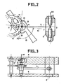
- the elements which are common to this figure and to FIG. 1 are the anchor 13, these two lifts 18 and 19, the spring 5, and the escape wheel 12.
- the means for adjusting the operation of the mechanism are always based on the fact that the spring is housed in a slot.
- first means are provided for adjusting the position of said slot in a direction orthogonal 20 to the axis of the spring 5. Therefore, whatever the causes of possible deformations of the spring before its use, when the mechanism is at rest the position of the anchor lifts 18 and 19, relative to the wheel, is adjustable. This therefore makes it possible to adjust the penetration depth of the anchor lifts between the teeth of the wheel.
- the two anchor lifts 18 and 19 are equidistant from the foot diameter 12, the return force of the spring 5 being the same on both sides of the oscillation, the penetration of the two lifts will be the same. If, on the other hand, at rest, the two anchor lifts are at different distances from the foot diameter, their respective penetrations between the teeth of the wheel will be different, during operation.
- the efficiency of the mechanism turns out to be maximum for the first rest position.
- the means for adjusting the slot are produced in FIG. 2 by two screws 1 mounted one opposite the other, that is to say head to tail, in a fixed part 2 relative to the axis 14 of the anchor 13.
- the axis of rotation of these screws is preferably coincident with the direction 20 orthogonal to the spring leaf 5.
- Another feature of the invention is to use these means for adjusting the position of the anchor lifts as means for adjusting the operating frequency. Indeed, the screws 1 as they are mounted, can be moved apart or brought closer so that the width of the slot 3 varies. The movement of the spring 5 inside the latter is thereby modified, and the operating frequency of the mechanism is thus adjustable.
- Figure 3 is a top view of Figure 2.
- the plates 4 are fixed and integral with the frame of the machine in which the adjustment device is used.
- the fixed part 2 can be made of plastic and wedged between the fixed plates 4.
- the anchor 13 can thus be mounted between these two plates.
- the slot in order to obtain self-starting, the slot must have a spacing between two values X and Y, outside of which the mechanism no longer works. Indeed, there is a distance X between the two screws 1 below which it is not possible to obtain self-starting. To this dimension corresponds too much bandage of the anchor spring which opposes the passage of the tooth of the escape wheel under the lift of the anchor. On the other hand, there is also a Y dimension above which this auto-start is again destroyed. This dimension corresponds to an engagement in the rest position of the lifting of the anchor in an area of the profile of the escape wheel where there is a self-jamming.
- the period difference is two and a half to three times greater than that obtained on the stroke of the old model adjusting nut ( Figure 1).
Landscapes
- Engineering & Computer Science (AREA)
- General Engineering & Computer Science (AREA)
- Physics & Mathematics (AREA)
- General Physics & Mathematics (AREA)
- Springs (AREA)
- Transmission Devices (AREA)
Applications Claiming Priority (2)
| Application Number | Priority Date | Filing Date | Title |
|---|---|---|---|
| FR8604521A FR2596537B1 (fr) | 1986-03-28 | 1986-03-28 | Dispositif de reglage d'un mecanisme d'horlogerie du type a echappement a ancre et utilisation dans une fusee eclairante |
| FR8604521 | 1986-03-28 |
Publications (2)
| Publication Number | Publication Date |
|---|---|
| EP0244331A1 true EP0244331A1 (de) | 1987-11-04 |
| EP0244331B1 EP0244331B1 (de) | 1990-02-07 |
Family
ID=9333680
Family Applications (1)
| Application Number | Title | Priority Date | Filing Date |
|---|---|---|---|
| EP19870450005 Expired - Lifetime EP0244331B1 (de) | 1986-03-28 | 1987-03-27 | Verstellvorrichtung eines Uhrenmechanismus mit Ankerhemmung und Verwendung in einer Leuchtrakete |
Country Status (3)
| Country | Link |
|---|---|
| EP (1) | EP0244331B1 (de) |
| DE (1) | DE3761712D1 (de) |
| FR (1) | FR2596537B1 (de) |
Cited By (1)
| Publication number | Priority date | Publication date | Assignee | Title |
|---|---|---|---|---|
| CN112177869A (zh) * | 2020-09-29 | 2021-01-05 | 重庆科技学院 | 用于摩擦纳米发电机的随机环境能收集和稳定释放装置 |
Families Citing this family (1)
| Publication number | Priority date | Publication date | Assignee | Title |
|---|---|---|---|---|
| CH720705A2 (fr) * | 2023-04-17 | 2024-10-31 | Rolex Sa | Procédé de réglage d'un système réglant comprenant un oscillateur et un échappement |
Citations (4)
| Publication number | Priority date | Publication date | Assignee | Title |
|---|---|---|---|---|
| BE522934A (de) * | 1953-09-10 | |||
| FR364709A (fr) * | 1905-03-29 | 1906-08-27 | Leon Paul Boillat | Raquetterie |
| FR370181A (fr) * | 1905-10-12 | 1907-01-30 | Henri Coullery | échappement à grande variation de marche pour mécanismes d'horlogerie |
| FR808725A (fr) * | 1935-08-03 | 1937-02-13 | Junghans Geb Ag | Dispositif de ressort de balancier pour mouvements de montres et autres mécanismes d'horlogerie |
-
1986
- 1986-03-28 FR FR8604521A patent/FR2596537B1/fr not_active Expired
-
1987
- 1987-03-27 DE DE8787450005T patent/DE3761712D1/de not_active Expired - Fee Related
- 1987-03-27 EP EP19870450005 patent/EP0244331B1/de not_active Expired - Lifetime
Patent Citations (4)
| Publication number | Priority date | Publication date | Assignee | Title |
|---|---|---|---|---|
| FR364709A (fr) * | 1905-03-29 | 1906-08-27 | Leon Paul Boillat | Raquetterie |
| FR370181A (fr) * | 1905-10-12 | 1907-01-30 | Henri Coullery | échappement à grande variation de marche pour mécanismes d'horlogerie |
| FR808725A (fr) * | 1935-08-03 | 1937-02-13 | Junghans Geb Ag | Dispositif de ressort de balancier pour mouvements de montres et autres mécanismes d'horlogerie |
| BE522934A (de) * | 1953-09-10 |
Cited By (2)
| Publication number | Priority date | Publication date | Assignee | Title |
|---|---|---|---|---|
| CN112177869A (zh) * | 2020-09-29 | 2021-01-05 | 重庆科技学院 | 用于摩擦纳米发电机的随机环境能收集和稳定释放装置 |
| CN112177869B (zh) * | 2020-09-29 | 2024-01-30 | 重庆科技学院 | 用于摩擦纳米发电机的随机环境能收集和稳定释放装置 |
Also Published As
| Publication number | Publication date |
|---|---|
| FR2596537A1 (fr) | 1987-10-02 |
| DE3761712D1 (de) | 1990-03-15 |
| FR2596537B1 (fr) | 1988-07-01 |
| EP0244331B1 (de) | 1990-02-07 |
Similar Documents
| Publication | Publication Date | Title |
|---|---|---|
| EP2048548B1 (de) | Schlagwerk | |
| EP0229086B1 (de) | Geschosszünder | |
| EP1528443B1 (de) | Konstantkraftvorrichtung für eine Uhr | |
| CH705814B1 (fr) | Echappement à ancre pour mouvement d'horlogerie. | |
| EP1367462A1 (de) | Hemmung für Uhren | |
| EP0244331B1 (de) | Verstellvorrichtung eines Uhrenmechanismus mit Ankerhemmung und Verwendung in einer Leuchtrakete | |
| EP3121661B1 (de) | Direkter uhrhemmungsmechanismus mit konstanter kraft | |
| EP1139182A1 (de) | Anzeigemechanismus der Gangreserve einer Uhr und mit diesem Mechanismus versehene Uhr | |
| EP1272906B1 (de) | Hemmung für uhr | |
| EP4194959B1 (de) | Natürliche hemmung für uhrwerk und uhrwerk, das eine solche uhrhemmung umfasst | |
| EP2102718A1 (de) | Klingeltonmechanismus zur stundenanzeige | |
| EP1857890B1 (de) | Vorrichtung zur Auslösung eines Impulses | |
| EP3206088A1 (de) | Hemmungsmechanismus | |
| EP3401739A1 (de) | Uhrwerk, das eine konstantkraftvorrichtung umfasst | |
| EP3599514A1 (de) | Hemmungsmechanismus mit bistabilen und monostabilen federn | |
| EP3486735A1 (de) | Uhrwerksmechanismus zur nullrückstellung der sekunde mit schneckennocken | |
| CH719059A1 (fr) | Dispositif horloger comprenant un marteau comportant deux parties reliées entre elles par un organe de guidage flexible. | |
| FR2588392A1 (fr) | Roue d'echappement et dispositif d'horlogerie a echappement a ancre utilisable dans une fusee d'obus de mortier eclairante | |
| EP4075204A1 (de) | Sperrklinke für uhrwerk | |
| EP4312083A1 (de) | Kupplungs-ausrückvorrichtung für uhr | |
| CH715196A2 (fr) | Mouvement d'horlogerie comportant un bras porteur d'un satellite que comporte un tourbillon ou carrousel. | |
| CH301862A (fr) | Mécanisme de seconde sautante. | |
| CH717664B1 (fr) | Pièce d'horlogerie comprenant un dispositif de commande étanche. | |
| WO2025190470A1 (fr) | Mouvement horloger comprenant un mécanisme de remontage automatique | |
| CH721478A2 (fr) | Dispositif régulateur pour mouvement horloger, mouvement horloger et pièce d'horlogerie |
Legal Events
| Date | Code | Title | Description |
|---|---|---|---|
| PUAI | Public reference made under article 153(3) epc to a published international application that has entered the european phase |
Free format text: ORIGINAL CODE: 0009012 |
|
| AK | Designated contracting states |
Kind code of ref document: A1 Designated state(s): CH DE IT LI SE |
|
| 17P | Request for examination filed |
Effective date: 19880425 |
|
| 17Q | First examination report despatched |
Effective date: 19890523 |
|
| GRAA | (expected) grant |
Free format text: ORIGINAL CODE: 0009210 |
|
| AK | Designated contracting states |
Kind code of ref document: B1 Designated state(s): CH DE IT LI SE |
|
| PG25 | Lapsed in a contracting state [announced via postgrant information from national office to epo] |
Ref country code: IT Free format text: LAPSE BECAUSE OF FAILURE TO SUBMIT A TRANSLATION OF THE DESCRIPTION OR TO PAY THE FEE WITHIN THE PRE;WARNING: LAPSES OF ITALIAN PATENTS WITH EFFECTIVE DATE BEFORE 2007 MAY HAVE OCCURRED AT ANY TIME BEFORE 2007. THE CORRECT EFFECTIVE DATE MAY BE DIFFERENT FROM THE ONE RECORDED.SCRIBED TIME-LIMIT Effective date: 19900207 Ref country code: SE Effective date: 19900207 |
|
| REF | Corresponds to: |
Ref document number: 3761712 Country of ref document: DE Date of ref document: 19900315 |
|
| PG25 | Lapsed in a contracting state [announced via postgrant information from national office to epo] |
Ref country code: LI Effective date: 19900331 Ref country code: CH Effective date: 19900331 |
|
| PLBE | No opposition filed within time limit |
Free format text: ORIGINAL CODE: 0009261 |
|
| STAA | Information on the status of an ep patent application or granted ep patent |
Free format text: STATUS: NO OPPOSITION FILED WITHIN TIME LIMIT |
|
| REG | Reference to a national code |
Ref country code: CH Ref legal event code: PL |
|
| PG25 | Lapsed in a contracting state [announced via postgrant information from national office to epo] |
Ref country code: DE Effective date: 19901201 |
|
| 26N | No opposition filed |