EP0244343A2 - Méthode pour réaliser un revêtement résistant à l'abrasion - Google Patents
Méthode pour réaliser un revêtement résistant à l'abrasion Download PDFInfo
- Publication number
- EP0244343A2 EP0244343A2 EP87630074A EP87630074A EP0244343A2 EP 0244343 A2 EP0244343 A2 EP 0244343A2 EP 87630074 A EP87630074 A EP 87630074A EP 87630074 A EP87630074 A EP 87630074A EP 0244343 A2 EP0244343 A2 EP 0244343A2
- Authority
- EP
- European Patent Office
- Prior art keywords
- powder
- stream
- particles
- substrate
- deposit
- Prior art date
- Legal status (The legal status is an assumption and is not a legal conclusion. Google has not performed a legal analysis and makes no representation as to the accuracy of the status listed.)
- Granted
Links
Images
Classifications
-
- C—CHEMISTRY; METALLURGY
- C23—COATING METALLIC MATERIAL; COATING MATERIAL WITH METALLIC MATERIAL; CHEMICAL SURFACE TREATMENT; DIFFUSION TREATMENT OF METALLIC MATERIAL; COATING BY VACUUM EVAPORATION, BY SPUTTERING, BY ION IMPLANTATION OR BY CHEMICAL VAPOUR DEPOSITION, IN GENERAL; INHIBITING CORROSION OF METALLIC MATERIAL OR INCRUSTATION IN GENERAL
- C23C—COATING METALLIC MATERIAL; COATING MATERIAL WITH METALLIC MATERIAL; SURFACE TREATMENT OF METALLIC MATERIAL BY DIFFUSION INTO THE SURFACE, BY CHEMICAL CONVERSION OR SUBSTITUTION; COATING BY VACUUM EVAPORATION, BY SPUTTERING, BY ION IMPLANTATION OR BY CHEMICAL VAPOUR DEPOSITION, IN GENERAL
- C23C4/00—Coating by spraying the coating material in the molten state, e.g. by flame, plasma or electric discharge
- C23C4/04—Coating by spraying the coating material in the molten state, e.g. by flame, plasma or electric discharge characterised by the coating material
-
- B—PERFORMING OPERATIONS; TRANSPORTING
- B05—SPRAYING OR ATOMISING IN GENERAL; APPLYING FLUENT MATERIALS TO SURFACES, IN GENERAL
- B05B—SPRAYING APPARATUS; ATOMISING APPARATUS; NOZZLES
- B05B7/00—Spraying apparatus for discharge of liquids or other fluent materials from two or more sources, e.g. of liquid and air, of powder and gas
- B05B7/16—Spraying apparatus for discharge of liquids or other fluent materials from two or more sources, e.g. of liquid and air, of powder and gas incorporating means for heating or cooling the material to be sprayed
- B05B7/22—Spraying apparatus for discharge of liquids or other fluent materials from two or more sources, e.g. of liquid and air, of powder and gas incorporating means for heating or cooling the material to be sprayed electrically, magnetically or electromagnetically, e.g. by arc
- B05B7/222—Spraying apparatus for discharge of liquids or other fluent materials from two or more sources, e.g. of liquid and air, of powder and gas incorporating means for heating or cooling the material to be sprayed electrically, magnetically or electromagnetically, e.g. by arc using an arc
- B05B7/226—Spraying apparatus for discharge of liquids or other fluent materials from two or more sources, e.g. of liquid and air, of powder and gas incorporating means for heating or cooling the material to be sprayed electrically, magnetically or electromagnetically, e.g. by arc using an arc the material being originally a particulate material
-
- B—PERFORMING OPERATIONS; TRANSPORTING
- B22—CASTING; POWDER METALLURGY
- B22F—WORKING METALLIC POWDER; MANUFACTURE OF ARTICLES FROM METALLIC POWDER; MAKING METALLIC POWDER; APPARATUS OR DEVICES SPECIALLY ADAPTED FOR METALLIC POWDER
- B22F3/00—Manufacture of workpieces or articles from metallic powder characterised by the manner of compacting or sintering; Apparatus specially adapted therefor ; Presses and furnaces
- B22F3/115—Manufacture of workpieces or articles from metallic powder characterised by the manner of compacting or sintering; Apparatus specially adapted therefor ; Presses and furnaces by spraying molten metal, i.e. spray sintering, spray casting
-
- B—PERFORMING OPERATIONS; TRANSPORTING
- B22—CASTING; POWDER METALLURGY
- B22F—WORKING METALLIC POWDER; MANUFACTURE OF ARTICLES FROM METALLIC POWDER; MAKING METALLIC POWDER; APPARATUS OR DEVICES SPECIALLY ADAPTED FOR METALLIC POWDER
- B22F7/00—Manufacture of composite layers, workpieces, or articles, comprising metallic powder, by sintering the powder, with or without compacting wherein at least one part is obtained by sintering or compression
- B22F7/002—Manufacture of composite layers, workpieces, or articles, comprising metallic powder, by sintering the powder, with or without compacting wherein at least one part is obtained by sintering or compression of porous nature
-
- C—CHEMISTRY; METALLURGY
- C23—COATING METALLIC MATERIAL; COATING MATERIAL WITH METALLIC MATERIAL; CHEMICAL SURFACE TREATMENT; DIFFUSION TREATMENT OF METALLIC MATERIAL; COATING BY VACUUM EVAPORATION, BY SPUTTERING, BY ION IMPLANTATION OR BY CHEMICAL VAPOUR DEPOSITION, IN GENERAL; INHIBITING CORROSION OF METALLIC MATERIAL OR INCRUSTATION IN GENERAL
- C23C—COATING METALLIC MATERIAL; COATING MATERIAL WITH METALLIC MATERIAL; SURFACE TREATMENT OF METALLIC MATERIAL BY DIFFUSION INTO THE SURFACE, BY CHEMICAL CONVERSION OR SUBSTITUTION; COATING BY VACUUM EVAPORATION, BY SPUTTERING, BY ION IMPLANTATION OR BY CHEMICAL VAPOUR DEPOSITION, IN GENERAL
- C23C4/00—Coating by spraying the coating material in the molten state, e.g. by flame, plasma or electric discharge
- C23C4/12—Coating by spraying the coating material in the molten state, e.g. by flame, plasma or electric discharge characterised by the method of spraying
- C23C4/134—Plasma spraying
-
- B—PERFORMING OPERATIONS; TRANSPORTING
- B22—CASTING; POWDER METALLURGY
- B22F—WORKING METALLIC POWDER; MANUFACTURE OF ARTICLES FROM METALLIC POWDER; MAKING METALLIC POWDER; APPARATUS OR DEVICES SPECIALLY ADAPTED FOR METALLIC POWDER
- B22F2998/00—Supplementary information concerning processes or compositions relating to powder metallurgy
-
- Y—GENERAL TAGGING OF NEW TECHNOLOGICAL DEVELOPMENTS; GENERAL TAGGING OF CROSS-SECTIONAL TECHNOLOGIES SPANNING OVER SEVERAL SECTIONS OF THE IPC; TECHNICAL SUBJECTS COVERED BY FORMER USPC CROSS-REFERENCE ART COLLECTIONS [XRACs] AND DIGESTS
- Y10—TECHNICAL SUBJECTS COVERED BY FORMER USPC
- Y10T—TECHNICAL SUBJECTS COVERED BY FORMER US CLASSIFICATION
- Y10T428/00—Stock material or miscellaneous articles
- Y10T428/249921—Web or sheet containing structurally defined element or component
- Y10T428/249953—Composite having voids in a component [e.g., porous, cellular, etc.]
- Y10T428/249967—Inorganic matrix in void-containing component
- Y10T428/24997—Of metal-containing material
Definitions
- the present invention relates to a method for providing sprayed coatings on a substrate. More specifically, it relates to a method for simultaneously thermal spraying two or more types of powders on a substrate using a single spray device.
- Gas turbine engines and other turbomachines have rows of blades which rotate within a generally cylindrical case. As the blades rotate, their tips move in close proximity to the case.
- One way to improve the efficiency of such machines is to minimize the leakage of the working fluid between the blade tips and the case. As has been known for some time, this leakage may be reduced by blade and seal systems, in which the blade tips rub against an abradable seal attached to the interior of the engine case.
- Porous metal structures are particularly useful for abradable seals, since they wear at a favorable rate when contacted by rotating blades.
- One method for making porous seals is to plasma spray a mixture of metal and polymer powder particles, generally according to the teachings of Longo in U.S. Patent No. 3,723,l65.
- powder particles of at least two different powder types are deposited onto a. substrate by a single thermal spray apparatus, in such a manner that there is little mixing of the different powder types in the high temperature gas stream.
- the different powder particle types are simultaneously injected through separate powder ports and at independently controlled feed rates into a stream of high temperature, high velocity gases; the powder ports are arranged and the powder feed rates adjusted such that the powder particles of a first powder type are carried along the central, hotter portion of the stream of gases and impact upon the substrate, while at the same time, the particles of a second powder type are carried along the outer, cooler portion of the stream of gases and impact upon the substrate. Due to their separate paths of travel, there is little mixing of the first powder particles with the second powder particles in the gas stream; a composite, homogeneous deposit is achieved by moving the substrate relative to the stream of gases while the powders are being injected into the stream.
- Spraying the powders so that there is little mixing of the powder particles in the gas stream has produced deposits having significantly improved properties compared to deposits produced when the powders are mixed before they reach the stream as in the Longo patent, or mixed in the stream as in the Eaton et al patent.
- the invention has been particularly useful in simultaneously spraying powders having different melting temperatures, such as metal and plastic, of the type described in U.S. Serial No. 8l5,6l6.
- the metal particles are injected into the hot portion of the stream, and their dwell time in the stream is longer than the dwell time of the plastic particles, which are injected into the cool portion of the stream. Neither the metal nor the plastic particles are excessively vaporized.
- the microstructure of the as-sprayed deposit exhibits a uniform distribution of polymer particles within a metal matrix. After the deposition process, the deposit is heated at a temperature which causes the polymer to volatilize, which results in a porous metal structure.
- the present invention relates to a method for simultaneously thermal spraying two or more different types of powders onto a substrate with a single spray apparatus.
- thermal spraying is meant to describe plasma spraying, combustion spraying, and other similar processes for the deposition of powders onto a substrate.
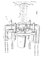
- the substrate to be coated is represented by the reference numeral l0
- the apparatus used to deposit the powders onto the substrate l0 is represented by the reference numeral l2.
- the power supply means and apparatus associated therewith are also not shown.
- the specific manner in which the substrate l0 and apparatus l2 are moved is not critical to the invention. Either the substrate l0 may be moved while the apparatus l2 is kept in a fixed position, the apparatus l2 moved while the substrate l0 is kept in a fixed position, or the substrate l0 and apparatus l2 both moved.
- Those skilled in the art will be able to adapt appropriate moving means to the spray system in whatever manner is best suited to meet the needs of the particular deposition process.
- the apparatus l2 includes a gun assembly l4.
- the gun assembly l4 is of the plasma arc type.
- Primary and secondary gases e.g., helium, argon, or nitrogen, or mixtures thereof, pass through the arc, and are ionized to form a high temperature, high velocity plasma plume or stream l5 which extends in a downstream direction from the gun nozzle l9 towards the substrate l0.
- the gun nozzle l9 is typically water cooled.
- a fixturing bracket l6 is attached to the front end l7 of the gun assembly l4 by means not shown in the Figure. Attached to the bracket l6 are nozzles l8 which spray a stream of cooling gases onto the substrate l0 to prevent the substrate l0 from being excessively heated by the plasma stream l5.
- Useful cooling gases include e.g., nitrogen, argon, or air.
- powder ports are arranged to direct separate streams of powder particles into the plasma stream l5. First powder ports 22 direct particles of a first type of powder 23 into the stream l5, and second powder ports 24 direct particles of a second type of powder 25 into the stream l5.
- the Figure shows two first powder ports 22 about l80° from each other, and two second powder ports 24 about l80° from each other, and generally radially aligned with the position of the first powder ports 22.
- the first powder ports 22 are axially upstream of the second powder ports 24, and are constructed and arranged to inject the first powder particles 23 into the stream l5 at a distance A from the front end l7 of the gun assembly l4; the second powder ports 24 inject the second powder particles 25 into the stream l5 at a downstream distance B.
- the distance between the gun front end l7 and the substrate l0 is designated C.
- the residence or dwell time of the second powder particles 25 in the plasma stream l5 is less than the dwell time of the first powder particles 23.
- Powder particles 23, 25 are delivered to the powder ports 22 and 24 by lines 32 and 34, respectively.
- the lines 32, 34 are pressurized with a carrier gas which is typically argon.
- the two feed lines 32 are each connected to a separate powder feeder which contain the first powder particles 23, and the two feed lines 34 are each connected to a separate powder feeder which contain the second powder particles 25. All powder feeders are independently controllable to deliver powder at a specified rate and velocity to and through their respective powder ports.
- the plasma stream l5 spreads radially outwardly from the stream axis 26 as the downstream distance from the gun front end l7 increases.
- the resulting overall shape of the stream l5 is similar to that of a tapered cylinder.
- the plasma stream l5 actually comprises a central stream of moving gases 40 and a radially outer, peripheral stream of moving gases 42.
- the diameter d c of the central stream 40 increases only slightly as the downstream distance increases, while the diameter d o of the outer stream 42 increases to a much greater extent as the downstream distance increases.
- the temperature as well as the velocity of the gases within the central plasma stream 40 is considerably higher than the temperature and velocity of the gases in the outer stream 42.
- each first powder feeder is selected to inject a substantially continuous flow of powder particles of the first powder type through its respective first powder port 22 and directly into the central stream of gases 40.
- the first powder particles 23 are carried by the central stream 40 until they impact upon the substrate l0. Tests have shown that there is little radial deviation of the first powder particles 23 outside of the central stream 40, apparently due to their relatively high axial momentum in the stream l5, although other forces may be acting to produce this effect.
- each second powder feeder is selected to inject the second powder particles 25 into the plasma stream l5 such that they do not enter the central stream of gases 40. Rather, the second powder particles 25 are carried by the outer stream of gases 42 until they impact upon the substrate l0. Whether the different powder particles 23, 25 are properly injected into their respective plasma stream portion 40, 42 and are carried by such stream portion to the substrate l0, can be determined by evaluating the distribution of the powder particles 23, 25 in the stream l5. A method for making such an evaluation is described below, in the discussion of Figure 2.
- the outer stream of gas 42, carrying the second powder particles 25, swirls in a circular fashion around the central stream of gases 40 and first powder particles 23 as they move in the downstream direction toward the substrate l0. Because the first powder particles 23 and second powder particles 25 are carried to the substrate l0 by separate gas streams 40, 42, the particles 23, 25 do not mix to any appreciable degree within the plasma stream l5. This is unlike prior art plasma spray processes, wherein the different powder types are deliberately mixed with each other within the plasma stream or are mixed in a mixing chamber which then delivers the powders through a singular powder port into the plasma stream.
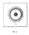
- Figure 2 shows that there is a lack of substantial mixing of the first and second powder particles 23, 25 respectively, in the plasma stream l5.
- the Figure is a schematic representation of a photograph of a substrate l0 which was sprayed according to the invention for one second. This was accomplished by placing a shutter type device between the gun assembly l4 and the substrate l0, and opening the shutter for one second while the powders 23, 25 were being injected into the plasma stream l5.
- the first powder particles 23 remained in the central stream of gases 40 and the second powder particles remained in the radially outer portion of the stream of gases 42, with only a small amount of mixing of the two powder types.
- the fact that most of the powders remain in their respective portion of the plasma stream is significant in assuring process and product repeatability.
- the characteristics (temperature, velocity, etc.) of the central and outer portions of the stream 40, 42, respectively are closely controlled to the optimum range for spraying the different powder types.
- the characteristics of the central portion of the stream are adjusted to produce the best conditions for spraying the first powder type, while at the same time the characteristics of the outer portion of the stream are adjusted to produce the best conditions for spraying the second powder type.
- the present invention is particularly useful in the thermal spray deposition of powder types which have different melting temperatures and densities to form a porous metal structure for turbomachinery such as gas turbine engines.
- the first powder type may be a metallic, oxidation resistant material such as an MCrAlY, where M is nickel, cobalt, iron, or mixtures thereof.
- MCrAlY oxidation resistant material
- Such compositions are described in, e.g., U.S. Patent Nos. 3,676,085, 3,928,026, and 4,4l9,4l6; the contents of each of these patents is incorporated by reference.
- Some MCrAlY compositions are modified to contain additions of noble metals, refractory metals, hafnium, silicon, and rare earth elements; see, e.g., U.S. Patent No. 4,4l9,4l6.
- One particularly useful refractory metal modified MCrAlY composition is described in copending and commonly assigned U.S. Serial No. 8l5,6l6.
- More simple metallic compositions may also be sprayed according to the invention, such as Ni-Cr alloys.
- the second powder type which may be sprayed with the metal powder to produce the porous structure is a decomposable polymer.
- the coated component is heated at a temperature which is sufficient to volatilize the polymer, which results in a porous metal structure which is particularly useful as an abradable seal for gas turbine engines.
- Seals produced according to the invention have shown superior properties compared to prior art seal materials.
- the metallic powder be produced by rotary atomization or rapid solidification rate (RSR) processing, such as described in, e.g., commonly assigned U.S. Patent Nos. 4,l78,335 and 4,284,394.
- RSR rapid solidification rate
- powders produced by the RSR process are, in general, more uniform in size, generally spherical in shape, and have a smoother surface finish.
- Such powders also flow through powder feeders and associated equipment more readily than do irregularly shaped and sized powder particles.
- smooth, uniformly sized and shaped particles are all heated to about the same temperature, which results in the spray process and the product produced thereby being more repeatable than those of the prior art.
- the polymer powder particles should also be uniform in size and shape, and have a smooth finish.
- refractory modified MCrAlY powder particles which were produced by RSR processing were sprayed with polymethylmecacrylate particles to produce a deposit which, with post-coating treatment (described below), has particular use as an abradable seal for gas turbine engines.
- the polymer powder particles were purchased from E. I. duPont Company (Wilmington, Delaware USA) as Lucite® Grade 4F powder; they were smooth in texture, spherical in shape, and within the size range (diameter) of about 60-l20 microns.
- the metallic powder particles were also smooth spheres, and about 50-90 microns in size. The density of the polymer and metallic particles was about 0.9 g/cc and 8.6 g/cc, respectively.
- the polymer and metal particles were fed by separate Plasmatron l250 series powder feeders (Plasmadyne Incorporated, Tustin, California USA) to a plasma spray system comprising a Metco 7M gun and Metco 705 nozzle (Metco Incorporated, Westbury, New York USA).
- the nozzle to metal injection point distance A was about 0.55 cm
- the nozzle to polymer injection point distance B was about 3.3 cm
- the nozzle to substrate distance C was about l8 cm.
- the radial distance between the first powder port outlet end 46 and the plasma stream axis 26 was about 0.7 cm
- the radial distance between the second powder port outlet end 44 and the stream axis 26 was about l.5 cm.
- Specific spray parameters used to deposit the powder are presented in Table I. The use of such parameters produced a spray pattern similar to that shown in Figure 2.
- the metal-polymer deposit is treated to eliminate the polymer particles, which results in a porous metal structure.
- the preferred method is to heat the deposit in a nonoxidizing atmosphere to about 355-385°C for two hours. This temperature is high enough to cause complete volatilization of the polymer.
- the polymer may also be removed chemically with appropriate solvents or the like. After the polymer is removed, the sprayed deposit is about two-thirds porous.
- porous sprayed MCrAlY deposits produced according to the teachings of the invention, have exhibited markedly improved properties as an abradable seal material as compared to prior art seal materials.
- Useful seal materials must be abradable, i.e., they must easily disintegrate in a friable mode when contacted by a high speed moving part, such as the tip of a rotating blade in a gas turbine engine, or the tip of a knife edge labyrinth type seal.
- the seal material must also remain intact when exposed to particulate erosion and other mechanical stresses.
- the porous metal abradable produced according to the invention exhibited better abradability and better erosion resistance compared to prior art seals.
Landscapes
- Engineering & Computer Science (AREA)
- Chemical & Material Sciences (AREA)
- Physics & Mathematics (AREA)
- Mechanical Engineering (AREA)
- Materials Engineering (AREA)
- Plasma & Fusion (AREA)
- Metallurgy (AREA)
- Chemical Kinetics & Catalysis (AREA)
- Organic Chemistry (AREA)
- Manufacturing & Machinery (AREA)
- Electromagnetism (AREA)
- Composite Materials (AREA)
- Coating By Spraying Or Casting (AREA)
- Nozzles (AREA)
- Application Of Or Painting With Fluid Materials (AREA)
- Other Surface Treatments For Metallic Materials (AREA)
Applications Claiming Priority (2)
| Application Number | Priority Date | Filing Date | Title |
|---|---|---|---|
| US856897 | 1986-04-28 | ||
| US06/856,897 US4696855A (en) | 1986-04-28 | 1986-04-28 | Multiple port plasma spray apparatus and method for providing sprayed abradable coatings |
Publications (3)
| Publication Number | Publication Date |
|---|---|
| EP0244343A2 true EP0244343A2 (fr) | 1987-11-04 |
| EP0244343A3 EP0244343A3 (en) | 1988-11-02 |
| EP0244343B1 EP0244343B1 (fr) | 1990-11-28 |
Family
ID=25324734
Family Applications (1)
| Application Number | Title | Priority Date | Filing Date |
|---|---|---|---|
| EP87630074A Expired - Lifetime EP0244343B1 (fr) | 1986-04-28 | 1987-04-24 | Méthode pour réaliser un revêtement résistant à l'abrasion |
Country Status (12)
| Country | Link |
|---|---|
| US (1) | US4696855A (fr) |
| EP (1) | EP0244343B1 (fr) |
| JP (1) | JP2586904B2 (fr) |
| CN (1) | CN1013688B (fr) |
| AU (1) | AU582989B2 (fr) |
| BR (1) | BR8702018A (fr) |
| CA (1) | CA1257511A (fr) |
| DD (1) | DD259586A5 (fr) |
| DE (1) | DE3766408D1 (fr) |
| IL (1) | IL82323A (fr) |
| NO (1) | NO170060C (fr) |
| YU (1) | YU45820B (fr) |
Cited By (5)
| Publication number | Priority date | Publication date | Assignee | Title |
|---|---|---|---|---|
| EP0455996A1 (fr) * | 1990-05-02 | 1991-11-13 | Sulzer Metco (US) Inc. | Poudre composite de métaux et non-métaux pour pulvérisation thermique |
| EP0897019A1 (fr) * | 1997-07-18 | 1999-02-17 | FINMECCANICA S.p.A. AZIENDA ANSALDO | Procédé et appareil pour la formation de revêtements céramiques poreux, en particulier revêtements de barrières thermiques, sur des substrats métalliques |
| WO2008058776A3 (fr) * | 2006-11-14 | 2008-07-31 | Siemens Ag | Couches adhésives rugueuses appliquées par dépôt physique en phase vapeur grande vitesse ou pulvérisation à froid |
| EP1970462A3 (fr) * | 2007-03-13 | 2010-12-15 | Pratt & Whitney Rocketdyne Inc. | Revêtement à base de métal à faible contrainte |
| WO2017058489A1 (fr) * | 2015-09-30 | 2017-04-06 | Apple Inc. | Procédés de contrôle de la couleur et de la texture de verres métalliques par soufflage et oxydation combinés |
Families Citing this family (54)
| Publication number | Priority date | Publication date | Assignee | Title |
|---|---|---|---|---|
| LU86431A1 (fr) * | 1986-05-16 | 1987-12-16 | Glaverbel | Procede de formation d'une masse refractaire sur une surface et melange de particules pour former une telle masse |
| US4753849A (en) * | 1986-07-02 | 1988-06-28 | Carrier Corporation | Porous coating for enhanced tubes |
| DE3625659A1 (de) * | 1986-07-29 | 1988-02-04 | Utp Schweissmaterial | Verfahren zum beschichten von bauteilen, sowie vorrichtung zur durchfuehrung des verfahrens |
| US5262206A (en) * | 1988-09-20 | 1993-11-16 | Plasma Technik Ag | Method for making an abradable material by thermal spraying |
| US4853515A (en) * | 1988-09-30 | 1989-08-01 | The Perkin-Elmer Corporation | Plasma gun extension for coating slots |
| LU87602A1 (fr) * | 1989-10-05 | 1991-05-07 | Glaverbel | Procede de formation d'une masse refractaire et lance de projection d'un melange de particules |
| GB2242143B (en) * | 1990-03-23 | 1993-07-28 | Rolls Royce Plc | Abradable seal coating and method of making the same |
| US5536022A (en) * | 1990-08-24 | 1996-07-16 | United Technologies Corporation | Plasma sprayed abradable seals for gas turbine engines |
| US5472487A (en) * | 1991-01-18 | 1995-12-05 | United Technologies Corporation | Molybdenum disilicide based materials with reduced coefficients of thermal expansion |
| US5690844A (en) * | 1996-08-26 | 1997-11-25 | General Electric Company | Powder feed for underwater welding |
| US5951892A (en) * | 1996-12-10 | 1999-09-14 | Chromalloy Gas Turbine Corporation | Method of making an abradable seal by laser cutting |
| US6402841B1 (en) | 1997-02-21 | 2002-06-11 | Akzo Nobel N.V. | Glue application device with glue conduit surrounding hardener conduit |
| TW440472B (en) * | 1997-03-12 | 2001-06-16 | Akzo Nobel Nv | A method for supplying a fluid |
| US5879753A (en) * | 1997-12-19 | 1999-03-09 | United Technologies Corporation | Thermal spray coating process for rotor blade tips using a rotatable holding fixture |
| US6089825A (en) * | 1998-12-18 | 2000-07-18 | United Technologies Corporation | Abradable seal having improved properties and method of producing seal |
| DE19926818B4 (de) * | 1999-06-12 | 2007-06-14 | Alstom | Schutzschicht für Turbinenschaufeln |
| SG88799A1 (en) * | 1999-12-17 | 2002-05-21 | United Technologies Corp | Abradable seal having improved properties |
| US6352264B1 (en) | 1999-12-17 | 2002-03-05 | United Technologies Corporation | Abradable seal having improved properties |
| JP4029375B2 (ja) * | 2000-06-21 | 2008-01-09 | スズキ株式会社 | 混合粉末溶射方法 |
| US6533285B2 (en) | 2001-02-05 | 2003-03-18 | Caterpillar Inc | Abradable coating and method of production |
| US6537021B2 (en) | 2001-06-06 | 2003-03-25 | Chromalloy Gas Turbine Corporation | Abradeable seal system |
| JP2003129212A (ja) * | 2001-10-15 | 2003-05-08 | Fujimi Inc | 溶射方法 |
| FR2854086B1 (fr) * | 2003-04-23 | 2007-03-30 | Saint Gobain Pont A Mousson | Procede de revetement par flamme et dispositif correspondant |
| CN1298881C (zh) * | 2004-10-28 | 2007-02-07 | 河北工业大学 | 反应等离子喷涂反应室装置 |
| DE102004055199B4 (de) * | 2004-11-16 | 2009-10-22 | Daimler Ag | Herstellungsverfahren für Gleitschichten aus Verbundmaterial |
| EP1844175B1 (fr) * | 2005-01-26 | 2008-08-20 | Volvo Aero Corporation | Procede et dispositif de pulverisation thermique |
| ITFI20050142A1 (it) * | 2005-06-23 | 2006-12-24 | Colorobbia Italiana Spa | Materiali per la ricopertura di corpi ceramici, processi per la loro preparazione loro uso e manufatti ceramici che li comprendono |
| SE529056C2 (sv) | 2005-07-08 | 2007-04-17 | Plasma Surgical Invest Ltd | Plasmaalstrande anordning, plasmakirurgisk anordning och användning av en plasmakirurgisk anordning |
| SE529058C2 (sv) | 2005-07-08 | 2007-04-17 | Plasma Surgical Invest Ltd | Plasmaalstrande anordning, plasmakirurgisk anordning, användning av en plasmakirurgisk anordning och förfarande för att bilda ett plasma |
| SE529053C2 (sv) | 2005-07-08 | 2007-04-17 | Plasma Surgical Invest Ltd | Plasmaalstrande anordning, plasmakirurgisk anordning och användning av en plasmakirurgisk anordning |
| US20070269151A1 (en) * | 2006-05-18 | 2007-11-22 | Hamilton Sundstrand | Lubricated metal bearing material |
| US7928338B2 (en) | 2007-02-02 | 2011-04-19 | Plasma Surgical Investments Ltd. | Plasma spraying device and method |
| US20100009093A1 (en) * | 2007-04-11 | 2010-01-14 | Scott Coguill L | Thermal spray formation of polymer coatings |
| US7589473B2 (en) * | 2007-08-06 | 2009-09-15 | Plasma Surgical Investments, Ltd. | Pulsed plasma device and method for generating pulsed plasma |
| US8735766B2 (en) | 2007-08-06 | 2014-05-27 | Plasma Surgical Investments Limited | Cathode assembly and method for pulsed plasma generation |
| EP2206805A1 (fr) * | 2009-01-08 | 2010-07-14 | Siemens Aktiengesellschaft | Couche de MCrAIX ayant des teneurs différentes en chrome et aluminium |
| US8613742B2 (en) | 2010-01-29 | 2013-12-24 | Plasma Surgical Investments Limited | Methods of sealing vessels using plasma |
| US9598972B2 (en) | 2010-03-30 | 2017-03-21 | United Technologies Corporation | Abradable turbine air seal |
| US8562290B2 (en) | 2010-04-01 | 2013-10-22 | United Technologies Corporation | Blade outer air seal with improved efficiency |
| US9089319B2 (en) | 2010-07-22 | 2015-07-28 | Plasma Surgical Investments Limited | Volumetrically oscillating plasma flows |
| US8692150B2 (en) * | 2011-07-13 | 2014-04-08 | United Technologies Corporation | Process for forming a ceramic abrasive air seal with increased strain tolerance |
| US10279365B2 (en) | 2012-04-27 | 2019-05-07 | Progressive Surface, Inc. | Thermal spray method integrating selected removal of particulates |
| FR2999457B1 (fr) | 2012-12-18 | 2015-01-16 | Commissariat Energie Atomique | Procede de revetement d'un substrat par un materiau abradable ceramique, et revetement ainsi obtenu. |
| WO2015142411A2 (fr) * | 2014-02-07 | 2015-09-24 | United Technologies Corporation | Article comprenant un revêtement multicouches |
| CA2967578C (fr) * | 2014-12-04 | 2021-03-16 | Progressive Surface, Inc. | Procede de pulverisation thermique integrant la suppression selectionnee de particules |
| US9896756B2 (en) * | 2015-06-02 | 2018-02-20 | United Technologies Corporation | Abradable seal and method of producing a seal |
| US10315249B2 (en) | 2016-07-29 | 2019-06-11 | United Technologies Corporation | Abradable material feedstock and methods and apparatus for manufacture |
| US20180030586A1 (en) | 2016-07-29 | 2018-02-01 | United Technologies Corporation | Outer Airseal Abradable Rub Strip Manufacture Methods and Apparatus |
| US10697464B2 (en) | 2016-07-29 | 2020-06-30 | Raytheon Technologies Corporation | Abradable material |
| JP6920676B2 (ja) * | 2017-04-19 | 2021-08-18 | パナソニックIpマネジメント株式会社 | 微粒子製造装置および微粒子製造方法 |
| CN108968701B (zh) * | 2017-06-01 | 2022-04-05 | 佛山市顺德区美的电热电器制造有限公司 | 不粘涂层及其制备方法以及锅具和煮食设备 |
| CN108579173A (zh) * | 2018-02-28 | 2018-09-28 | 铜陵市业强环保设备有限责任公司 | 一种用于链板带式真空过滤机的螺旋滚轮式刮刀卸料装置 |
| EP3640229B1 (fr) | 2018-10-18 | 2023-04-05 | Rolls-Royce Corporation | Revêtements de barrière résistants aux cmas |
| EP4205515A2 (fr) | 2020-08-28 | 2023-07-05 | Plasma Surgical Investments Limited | Systèmes, procédés et dispositifs pour générer un flux de plasma étendu principalement radialement |
Family Cites Families (15)
| Publication number | Priority date | Publication date | Assignee | Title |
|---|---|---|---|---|
| US2423490A (en) * | 1944-05-20 | 1947-07-08 | Erhardt Richard | Metal spraying method |
| US2689801A (en) * | 1949-07-11 | 1954-09-21 | Koppers Co Inc | Methods of producing coated articles |
| US3020182A (en) * | 1958-09-26 | 1962-02-06 | Gen Electric | Ceramic-to-metal seal and method of making the same |
| US3352492A (en) * | 1960-08-02 | 1967-11-14 | Powder Melting Corp | Method of and apparatus for depositing metal powder |
| CH513252A (de) * | 1967-12-15 | 1971-09-30 | Castolin Soudures | Verfahren zum thermischen Auftragen von Schichten |
| US3864443A (en) * | 1970-05-27 | 1975-02-04 | Arthur Hopkins | Method of making light-weight concrete aggregate |
| CA941643A (en) * | 1971-03-25 | 1974-02-12 | Union Carbide Corporation | Metal porous abradable seals |
| US3723165A (en) * | 1971-10-04 | 1973-03-27 | Metco Inc | Mixed metal and high-temperature plastic flame spray powder and method of flame spraying same |
| US3912235A (en) * | 1974-12-19 | 1975-10-14 | United Technologies Corp | Multiblend powder mixing apparatus |
| SE422427B (sv) * | 1977-10-17 | 1982-03-08 | Bertil Sandell | Sett att tillverka fiberarmerade byggnadskonstruktioner, ytbeleggningar och dylikt samt anordning for genomforande av settet |
| US4299865A (en) * | 1979-09-06 | 1981-11-10 | General Motors Corporation | Abradable ceramic seal and method of making same |
| US4336276A (en) * | 1980-03-30 | 1982-06-22 | The United States Of America As Represented By The Administrator Of The National Aeronautics And Space Administration | Fully plasma-sprayed compliant backed ceramic turbine seal |
| FR2511362B1 (fr) * | 1981-08-14 | 1987-01-02 | Nippon Steel Corp | Moulage refractaire obtenu par projection a la flamme, notamment pour reparer des fours de traitement thermique |
| US4386112A (en) * | 1981-11-02 | 1983-05-31 | United Technologies Corporation | Co-spray abrasive coating |
| DE3422718A1 (de) * | 1984-06-19 | 1986-01-09 | Plasmainvent AG, Zug | Vakuum-plasma-beschichtungsanlage |
-
1986
- 1986-04-28 US US06/856,897 patent/US4696855A/en not_active Expired - Lifetime
-
1987
- 1987-04-21 CA CA000535134A patent/CA1257511A/fr not_active Expired
- 1987-04-23 AU AU71956/87A patent/AU582989B2/en not_active Ceased
- 1987-04-24 IL IL8232387A patent/IL82323A/xx not_active IP Right Cessation
- 1987-04-24 EP EP87630074A patent/EP0244343B1/fr not_active Expired - Lifetime
- 1987-04-24 DE DE8787630074T patent/DE3766408D1/de not_active Expired - Lifetime
- 1987-04-27 YU YU76087A patent/YU45820B/sh unknown
- 1987-04-27 BR BR8702018A patent/BR8702018A/pt unknown
- 1987-04-27 NO NO871729A patent/NO170060C/no unknown
- 1987-04-27 DD DD87302163A patent/DD259586A5/de not_active IP Right Cessation
- 1987-04-28 JP JP10613687A patent/JP2586904B2/ja not_active Expired - Lifetime
- 1987-04-28 CN CN87103228A patent/CN1013688B/zh not_active Expired
Cited By (8)
| Publication number | Priority date | Publication date | Assignee | Title |
|---|---|---|---|---|
| EP0455996A1 (fr) * | 1990-05-02 | 1991-11-13 | Sulzer Metco (US) Inc. | Poudre composite de métaux et non-métaux pour pulvérisation thermique |
| US5122182A (en) * | 1990-05-02 | 1992-06-16 | The Perkin-Elmer Corporation | Composite thermal spray powder of metal and non-metal |
| EP0897019A1 (fr) * | 1997-07-18 | 1999-02-17 | FINMECCANICA S.p.A. AZIENDA ANSALDO | Procédé et appareil pour la formation de revêtements céramiques poreux, en particulier revêtements de barrières thermiques, sur des substrats métalliques |
| US6051279A (en) * | 1997-07-18 | 2000-04-18 | Finmeccanica S.P.A. Azienda Ansaldo | Method and device for forming porous ceramic coatings, in particular thermal barrier coating, on metal substrates |
| WO2008058776A3 (fr) * | 2006-11-14 | 2008-07-31 | Siemens Ag | Couches adhésives rugueuses appliquées par dépôt physique en phase vapeur grande vitesse ou pulvérisation à froid |
| EP1970462A3 (fr) * | 2007-03-13 | 2010-12-15 | Pratt & Whitney Rocketdyne Inc. | Revêtement à base de métal à faible contrainte |
| US7892652B2 (en) | 2007-03-13 | 2011-02-22 | United Technologies Corporation | Low stress metallic based coating |
| WO2017058489A1 (fr) * | 2015-09-30 | 2017-04-06 | Apple Inc. | Procédés de contrôle de la couleur et de la texture de verres métalliques par soufflage et oxydation combinés |
Also Published As
| Publication number | Publication date |
|---|---|
| CN87103228A (zh) | 1987-11-04 |
| DE3766408D1 (de) | 1991-01-10 |
| NO871729L (no) | 1987-10-29 |
| IL82323A0 (en) | 1987-10-30 |
| YU45820B (sh) | 1992-07-20 |
| NO170060B (no) | 1992-06-01 |
| NO170060C (no) | 1992-09-09 |
| IL82323A (en) | 1990-03-19 |
| AU582989B2 (en) | 1989-04-13 |
| BR8702018A (pt) | 1988-02-09 |
| JPS62267460A (ja) | 1987-11-20 |
| DD259586A5 (de) | 1988-08-31 |
| US4696855A (en) | 1987-09-29 |
| CA1257511A (fr) | 1989-07-18 |
| JP2586904B2 (ja) | 1997-03-05 |
| EP0244343A3 (en) | 1988-11-02 |
| AU7195687A (en) | 1987-10-29 |
| EP0244343B1 (fr) | 1990-11-28 |
| NO871729D0 (no) | 1987-04-27 |
| YU76087A (en) | 1988-12-31 |
| CN1013688B (zh) | 1991-08-28 |
Similar Documents
| Publication | Publication Date | Title |
|---|---|---|
| EP0244343B1 (fr) | Méthode pour réaliser un revêtement résistant à l'abrasion | |
| US4386112A (en) | Co-spray abrasive coating | |
| Herman | Plasma-sprayed coatings | |
| CA1161314A (fr) | Methode et dispositif de protection par plasma | |
| US5858470A (en) | Small particle plasma spray apparatus, method and coated article | |
| DE69822108T2 (de) | Verfahren zum Beschichten von Blattspitzen einer Turbine mittels einer thermischen Spritzmethode | |
| Talib et al. | Thermal spray coating technology: a review | |
| EP1705266A2 (fr) | Dépôt d'une couche de liaison sur des organes de machine par pulverisation à froid | |
| US20130065077A1 (en) | Process for Applying a Heat Shielding Coating System on a Metallic Substrate | |
| US6180260B1 (en) | Method for modifying the surface of a thermal barrier coating, and related articles | |
| US6963044B2 (en) | Coating apparatus and processes for forming low oxide coatings | |
| JP5599455B2 (ja) | 基材のコーティングのための方法及びコーティングを有する基材 | |
| US5529809A (en) | Method and apparatus for spraying molten materials | |
| US5858469A (en) | Method and apparatus for applying coatings using a nozzle assembly having passageways of differing diameter | |
| US5466907A (en) | Process for coating the internal surfaces of hollow bodies | |
| CA1065203A (fr) | Vaporisation thermique a l'aide d'un courant froid de plasma | |
| EP3276039B1 (fr) | Procédés et appareil de fabrication de bande de frottement abradable de joint d'air externe | |
| Smith et al. | Plasma processing of functionally graded materials part I: process diagnostics | |
| EP0505561A4 (en) | A low temperature process of applying high strength metal coatings to a substrate and article produced thereby | |
| CA1203718A (fr) | Enduit abrasif depose au plasma | |
| WO1997020636A1 (fr) | Appareil de projection de plasma a fines particules, procede afferent et article enduit | |
| Erker et al. | Hard Coatings on Light Metals: Deposition of Protective Coatings at Low Temperature With High Velocity Flame Spraying | |
| Smith et al. | to Forming | |
| Gasin | Impulse Plasma Flow Deposition of Protective Coatings |
Legal Events
| Date | Code | Title | Description |
|---|---|---|---|
| PUAI | Public reference made under article 153(3) epc to a published international application that has entered the european phase |
Free format text: ORIGINAL CODE: 0009012 |
|
| AK | Designated contracting states |
Kind code of ref document: A2 Designated state(s): CH DE FR GB LI SE |
|
| PUAL | Search report despatched |
Free format text: ORIGINAL CODE: 0009013 |
|
| AK | Designated contracting states |
Kind code of ref document: A3 Designated state(s): CH DE FR GB LI SE |
|
| 17P | Request for examination filed |
Effective date: 19890407 |
|
| 17Q | First examination report despatched |
Effective date: 19900301 |
|
| GRAA | (expected) grant |
Free format text: ORIGINAL CODE: 0009210 |
|
| AK | Designated contracting states |
Kind code of ref document: B1 Designated state(s): CH DE FR GB LI SE |
|
| ET | Fr: translation filed | ||
| REF | Corresponds to: |
Ref document number: 3766408 Country of ref document: DE Date of ref document: 19910110 |
|
| PLBE | No opposition filed within time limit |
Free format text: ORIGINAL CODE: 0009261 |
|
| STAA | Information on the status of an ep patent application or granted ep patent |
Free format text: STATUS: NO OPPOSITION FILED WITHIN TIME LIMIT |
|
| 26N | No opposition filed | ||
| EAL | Se: european patent in force in sweden |
Ref document number: 87630074.0 |
|
| REG | Reference to a national code |
Ref country code: GB Ref legal event code: IF02 |
|
| PGFP | Annual fee paid to national office [announced via postgrant information from national office to epo] |
Ref country code: GB Payment date: 20060314 Year of fee payment: 20 |
|
| PGFP | Annual fee paid to national office [announced via postgrant information from national office to epo] |
Ref country code: FR Payment date: 20060403 Year of fee payment: 20 |
|
| PGFP | Annual fee paid to national office [announced via postgrant information from national office to epo] |
Ref country code: SE Payment date: 20060404 Year of fee payment: 20 |
|
| PGFP | Annual fee paid to national office [announced via postgrant information from national office to epo] |
Ref country code: DE Payment date: 20060428 Year of fee payment: 20 |
|
| PGFP | Annual fee paid to national office [announced via postgrant information from national office to epo] |
Ref country code: CH Payment date: 20060608 Year of fee payment: 20 |
|
| REG | Reference to a national code |
Ref country code: GB Ref legal event code: PE20 |
|
| REG | Reference to a national code |
Ref country code: CH Ref legal event code: PL |
|
| EUG | Se: european patent has lapsed | ||
| PG25 | Lapsed in a contracting state [announced via postgrant information from national office to epo] |
Ref country code: GB Free format text: LAPSE BECAUSE OF EXPIRATION OF PROTECTION Effective date: 20070423 |