EP0244373A2 - Vorrichtung zum Zuführen von Signaturen für eine Buchbindemaschine - Google Patents
Vorrichtung zum Zuführen von Signaturen für eine Buchbindemaschine Download PDFInfo
- Publication number
- EP0244373A2 EP0244373A2 EP87830160A EP87830160A EP0244373A2 EP 0244373 A2 EP0244373 A2 EP 0244373A2 EP 87830160 A EP87830160 A EP 87830160A EP 87830160 A EP87830160 A EP 87830160A EP 0244373 A2 EP0244373 A2 EP 0244373A2
- Authority
- EP
- European Patent Office
- Prior art keywords
- signature
- signatures
- stack
- elevator
- feeder according
- Prior art date
- Legal status (The legal status is an assumption and is not a legal conclusion. Google has not performed a legal analysis and makes no representation as to the accuracy of the status listed.)
- Withdrawn
Links
- 241000252254 Catostomidae Species 0.000 claims description 4
- 238000006073 displacement reaction Methods 0.000 description 1
- 230000000694 effects Effects 0.000 description 1
- 238000009434 installation Methods 0.000 description 1
- 230000001105 regulatory effect Effects 0.000 description 1
- 239000007787 solid Substances 0.000 description 1
- 238000011144 upstream manufacturing Methods 0.000 description 1
Images


Classifications
-
- B—PERFORMING OPERATIONS; TRANSPORTING
- B65—CONVEYING; PACKING; STORING; HANDLING THIN OR FILAMENTARY MATERIAL
- B65H—HANDLING THIN OR FILAMENTARY MATERIAL, e.g. SHEETS, WEBS, CABLES
- B65H3/00—Separating articles from piles
- B65H3/08—Separating articles from piles using pneumatic force
- B65H3/0808—Suction grippers
Definitions
- the present invention relates to a signature feeder for a bookbinding machine, in particular accumulators, wire-stitching machines, or gatherer-stitchers.
- the object of the present invention is that of eliminating the disadvantages and limitations indicated above by providing a signature feeder which is structurally simple and of great reliability.
- a signature feeder characterised by the fact that it comprises an in-feed table for conveying signatures disposed in a stack adjacent one another and each in an almost vertical aspect to a signature separator operating to separate the signatures one at a time from the stack and transfer them to a signature elevator operating to raise them to an upper horizontal conveyor on which they are disposed in a partly overlapping shingle configuration
- the signature separator comprising a plurality of sucker devices mounted on arms turnable about a horizontal spindle and a plurality of rotatable discs each having a circumferential recess or notch able to receive the lower edge of a signature removed from the.
- a particular advantage of the present invention is that of providing a signature feeder machine which is able to guarantee the removal of a signle signature at a time from a stack of adjacent signatures.
- Another advantage of the present invention is that of providing a signature feeder machine which makes it possible to operate correctly on signatures of any different form.
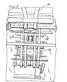
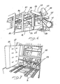
- the signature feeding machine of the invention comprises an in-feed table, generally indicated 1 which, as can be seen is slightly inclined in the direction of advance of the stacks of signatures 2.
- This in-feed table is constituted by a plate (not shown) over which run a series of toothed belts 3 having a high co-efficient of friction. These belts 3 pass over respective pairs of pulleys of which, as can be seen in Figures 3 and 4 those at the downstream end are mounted on a transverse shaft 5 itself driven via belts 6 and pulleys 7 from a geared motor unit 8.
- a device for separating individual signatures from the pack thereof constituted by an abutment 9a formed at the end of an arm 9 mounted at the opposite end on a pivot 10.
- a series of small arms 11 carrying respective suckers 12.
- the arms 11 are mounted on a transverse spindle 13 on which is keyed a sprocket 14 which engages a chain 15 which passes over two pulleys 16 and one end of which is attached to one end of a tension coil spring 17 fixed at its other end to the frame or side of the machine.
- the chain 15 is attached to the free end of a lever 18 pivoted at its other end 19 to a fixed part of the machine.
- the lever 18 In an intermediate position along its length the lever 18 carries a roller 20 which can engage a cam 21 keyed to a shaft 22.
- a signature elevator Adjacent the signature separator is a signature elevator comprising a plurality of adjacent conveyor belts 25 extending upwardly from the signature separator to an upper horizontal conveyor 30.
- a projection 26 to which is articulated one end of a rod 27 the opposite end of which is pivoted to the said cam-operated lever 18.
- the shaft 22 is driven to rotate and at each revolution the cam 21 acts by means of the rollers 20 on the lever 18 pressing it downwardly from the position shown in Figure 2. This causes a tension on the chain 15 which, moving against the tension of the spring 17 causes a corresponding rotation of the sucker arms 11 to the position shown in broken outline in Figure 2.
- the abutment 9a is-raised by the movement of the link rod 27 and the projection 26, turning the arm 9 in an anti-clockwise direction as viewed in Figure 2 presses the abutment 9a firmly against the remaining signatures of the stack, guaranteeing the removal of only the first signature.
- the abutment 9 is located at its lowest position such as to allow the withdrawal of the first signature from the stack when the suckers 12 start to move upon rotation of the arms . 11.
- a roller (not shown) mounted at the end of a lever shaped in such a way as to be movable between a position obscuring at least one photoelectric cell from a light source and a position where it does not obscure the photoelectric cell, in dependence on the thrust exerted on the roller itself by the stack of signatures on the in-feed table.
- the signatures As the signatures accumulate on the in-feed table 1 they gradually exert an increasing pressure until when there are a sufficiently high number of signatures present on the in-feed table the said lever, by interposing itself between the light source and the photocell, causes the signature advance device to stop until the thrust exerted by these latter on the said roller falls below a convenient predetermined value.
- the elevator conveyor belts 25 raise the signatures to the level of a horizontal conveyor 30 constituting an upper table, generally indicated 31 in Figure 1, on which the signatures are disposed in a partially overlapping position assuming the form of scales or shingles indicated by the reference numeral 32 in Figure 2.
- This effect is achieved by virtue of the fact that the said horizontal conveyor belts 30 run at a slower speed than the belts 25, and is aided by the action of pairs of wheels 33 acting in contact with the belts 30 themselves.
- This pair of wheels 33 is mounted on an axle carried for rotation at the end of an arm 34 articulated to a vertical bar 35 engaged on a horizontal screw threaded round bar 36 suspended by a frame structure 37 and provided at its free end with a toothed pinion 38.
- This frame structure 37 slidably carries a second frame structure 48 which is coupled thereto, also by means of a threaded bar 39 capable of being rotated by means of a handwheel 40 carrying a pinion 45 which meshes with the pinion 38.
- the second frame structure carries a second pair of wheels 41 supported by an arm 42 and driven to rotate by a belt 43 which takes drive from a shaft 44 on which the arm 42 is carried.
- the signature feeder machine is likewise provided, at the in-feed table 1, with two lateral containment walls 46 carrying at least one row of bearings 47 with vertical axes which allow free movement of the stack of signatures on the in-feed table and relieve the pressure exerted by the signatures situated upstream.
Landscapes
- Engineering & Computer Science (AREA)
- Mechanical Engineering (AREA)
- Sheets, Magazines, And Separation Thereof (AREA)
Applications Claiming Priority (2)
| Application Number | Priority Date | Filing Date | Title |
|---|---|---|---|
| IT2028786 | 1986-05-02 | ||
| IT20287/86A IT1191778B (it) | 1986-05-02 | 1986-05-02 | Macchina per l'alimentazione di segnatura o fogli,accoppiabile a macchine per legatoria,in particolare a raccoglitori o cucitrici-accavallatrici a punto metallico |
Publications (2)
| Publication Number | Publication Date |
|---|---|
| EP0244373A2 true EP0244373A2 (de) | 1987-11-04 |
| EP0244373A3 EP0244373A3 (de) | 1989-03-22 |
Family
ID=11165450
Family Applications (1)
| Application Number | Title | Priority Date | Filing Date |
|---|---|---|---|
| EP87830160A Withdrawn EP0244373A3 (de) | 1986-05-02 | 1987-04-30 | Vorrichtung zum Zuführen von Signaturen für eine Buchbindemaschine |
Country Status (3)
| Country | Link |
|---|---|
| US (1) | US4768770A (de) |
| EP (1) | EP0244373A3 (de) |
| IT (1) | IT1191778B (de) |
Families Citing this family (13)
| Publication number | Priority date | Publication date | Assignee | Title |
|---|---|---|---|---|
| US5100116A (en) * | 1988-12-19 | 1992-03-31 | Quad/Tech, Inc. | Apparatus and method of processing signatures |
| US5375824A (en) * | 1993-03-17 | 1994-12-27 | R. R. Donnelley & Sons Company | Selectable pin spacing on gathering chain |
| EP0755886B1 (de) * | 1995-07-25 | 2000-10-11 | Ferag AG | Vorrichtung zum Zubringen von Druckereiprodukten zu einer Weiterverarbeitungsstelle |
| US5685533A (en) * | 1996-02-14 | 1997-11-11 | R. R. Donnelley & Sons Company | Signature pocket apparatus and method of make ready |
| US6015145A (en) * | 1997-11-03 | 2000-01-18 | Hartel; Siegfried | Separator guide for Z-folded sheets |
| US6547231B1 (en) * | 2000-04-13 | 2003-04-15 | Usa Leader, Llc | Apparatus for placing inserts of different thicknesses and widths into newspaper jackets |
| IT1317704B1 (it) * | 2000-05-29 | 2003-07-15 | Sitma Spa | Procedimento di alimentazione di prodotti in foglio ad untrasportatore e gruppo di prelievo. |
| US6623000B2 (en) | 2001-06-15 | 2003-09-23 | Prim Hall Enterprises Inc. | Apparatus and method for separating sheet material by means of a reciprocating disk separator |
| US6659448B2 (en) * | 2001-10-30 | 2003-12-09 | Heidelberger Druckmaschinen Ag | Adjustable separator for a sheet separating device |
| US6742778B2 (en) | 2002-03-18 | 2004-06-01 | Quad/Graphics, Inc. | Signature hopper loader |
| US7677543B2 (en) * | 2004-06-18 | 2010-03-16 | Terje Gulbrandsen | Sheet handling apparatus |
| WO2011035226A1 (en) * | 2009-09-18 | 2011-03-24 | Steven Krengel | Paper-towel apparatus for reusing non-structured paperless paper-towels |
| US11220409B2 (en) * | 2011-10-31 | 2022-01-11 | Ncr Corporation | Single item removal |
Family Cites Families (7)
| Publication number | Priority date | Publication date | Assignee | Title |
|---|---|---|---|---|
| GB785414A (en) * | 1955-04-20 | 1957-10-30 | Aetna Standard Eng Co | Sheet feeding apparatus |
| US4253651A (en) * | 1979-01-30 | 1981-03-03 | Technitrol, Inc. | Document interleaver device |
| DE3135588C2 (de) * | 1980-10-07 | 1983-11-17 | WUFAG AG, 8868 Oberurnen | Vorrichtung zum Vereinzeln von Bogen von einem Stapel, insbesondere für eine Zusammentragmaschine |
| IT8320854V0 (it) * | 1983-02-18 | 1983-02-18 | Sitma | Caricatore a nastro di segnature, fogli, riviste e prodotti simili per alimentatori di macchine confezionatrici, di macchine per legatoria e simili. |
| EP0141806B1 (de) * | 1983-11-09 | 1987-09-09 | ELBAK Batteriewerke Gesellschaft m.b.H. | Magazin für plattenförmige Gegenstände |
| US4564186A (en) * | 1984-06-04 | 1986-01-14 | R. R. Donnelley & Sons Company | Apparatus for gathering printed signatures for saddle stitching |
| DE3526884A1 (de) * | 1985-07-26 | 1987-01-29 | Zimmermann Anso Dr Rotpunkt | Kanne oder flasche aus kunststoff, insbesondere kunststoffmantel einer isolierkanne oder -flasche, mit einer relief-verzierung auf der mantelflaeche |
-
1986
- 1986-05-02 IT IT20287/86A patent/IT1191778B/it active
-
1987
- 1987-04-29 US US07/044,044 patent/US4768770A/en not_active Expired - Fee Related
- 1987-04-30 EP EP87830160A patent/EP0244373A3/de not_active Withdrawn
Also Published As
| Publication number | Publication date |
|---|---|
| US4768770A (en) | 1988-09-06 |
| IT8620287A0 (it) | 1986-05-02 |
| IT1191778B (it) | 1988-03-23 |
| EP0244373A3 (de) | 1989-03-22 |
| IT8620287A1 (it) | 1987-11-02 |
Similar Documents
| Publication | Publication Date | Title |
|---|---|---|
| US4169341A (en) | Document collating and envelope stuffing apparatus | |
| US4768770A (en) | Signature feeder for a bookbinding machine | |
| US4320894A (en) | Apparatus for outfeeding flat products, especially printed products, arriving in an imbricated array | |
| CA2062602C (en) | Enveloping device | |
| US3343334A (en) | Method and apparatus fof bundling stacked material | |
| US4424660A (en) | Apparatus for binding paper sheets | |
| US5126002A (en) | Leaf paper bundling apparatus | |
| CA1135734A (en) | Document sheet flipper | |
| JPH0637256B2 (ja) | 包装機、製本機等のフイ−ダに適した、折り丁、シ−ト及び類似の製品のロ−ダ | |
| US4330116A (en) | Bundling mechanism for signatures | |
| US3982749A (en) | Signature feeder | |
| US4482141A (en) | Method and apparatus for conveying folded sheets using orbitally gripping and releasing clamp pads | |
| EP0107424A1 (de) | Stapelvorrichtung für gefaltete Blätter | |
| US4240539A (en) | Backup station for a carton filling machine | |
| JP2530208Y2 (ja) | シート状ブランクを容器へ充填する装置 | |
| US3810612A (en) | Method and apparatus for handling sheet materials, signatures and the like | |
| EP0192211A2 (de) | Vorrichtung zum Zählen und Stapeln von Bögen | |
| US5954473A (en) | Readily adjustable cut sheet stacker | |
| US4222313A (en) | Machine for counting flat articles | |
| EP0611718B1 (de) | Vorrichtung zum Stapeln von Bogen | |
| EP0768260B1 (de) | Vorrichtung zum Handhaben von Papier | |
| US4214742A (en) | Device for feeding sheets to boxing machines | |
| US3628787A (en) | Stacking device | |
| US6349933B1 (en) | Method and apparatus for horizontal stacking and batching of sheet products | |
| US4736571A (en) | Envelope stacker |
Legal Events
| Date | Code | Title | Description |
|---|---|---|---|
| PUAI | Public reference made under article 153(3) epc to a published international application that has entered the european phase |
Free format text: ORIGINAL CODE: 0009012 |
|
| AK | Designated contracting states |
Kind code of ref document: A2 Designated state(s): CH DE ES FR GB LI NL SE |
|
| PUAL | Search report despatched |
Free format text: ORIGINAL CODE: 0009013 |
|
| AK | Designated contracting states |
Kind code of ref document: A3 Designated state(s): CH DE ES FR GB LI NL SE |
|
| 17P | Request for examination filed |
Effective date: 19890712 |
|
| 17Q | First examination report despatched |
Effective date: 19901212 |
|
| STAA | Information on the status of an ep patent application or granted ep patent |
Free format text: STATUS: THE APPLICATION HAS BEEN WITHDRAWN |
|
| 18W | Application withdrawn |
Withdrawal date: 19910423 |
|
| R18W | Application withdrawn (corrected) |
Effective date: 19910423 |
|
| RIN1 | Information on inventor provided before grant (corrected) |
Inventor name: PEROBELLI, ALDO Inventor name: PESSINA, GIORGIO |